Page is loading ...

ISS1-2 Data Sheet (NZ327) Page 1Texmate, Inc. Tel. (760) 598-9899 • www.texmate.com
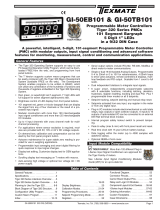
16-BIT SMART LOAD CELL INPUT MODULE
Interface to
Tiger Meter.
On-board Excitation
Voltage Generator.
Enough to power 8 x 350 Ω bridges.
On-board Digital Signal
Processor.
Provides six output functions
including Texmate's unique
dual output rates.
Crystal
Controlled 50/60 Hz
Noise Rejection option.
6-wire or 4-wire Bridge Header
selectable.
Ultra-low Noise 16-Bit
A/D Convertor.
Approaching 19-bit performance
with additional software filtering.
8-pin Input
Connector.
State-of-the-art
Electromagnetic Noise
Suppression Circuitry.
Ensures signal integrity even in
harsh EMC environments.
Hardware Module Specifications
Excitation 5 V DC, 130 mA maximum.
Input Range Software selectable for sensors from 1 mV/V to 20 mV/V.
Input Sensitivity 0.08 µV/Count maximum.
Zero Drift ± 40 nV/ °C typical.
Span Drift ± 5 ppm/ ° C of full scale maximum.
Non-linearity ± 0.003% of full scale maximum.
Input Noise 160 nVpp typical at 1 Hz output rate.
Signal processing Rate 50 Hz maximum, 1 Hz minimum.
Software Module Features
Dual output rates Rapid and average response outputs.
Ideal for 2 and 3-speed weighing / bagging systems.
Peak & Valley Outputs Monitoring over and under-shoots.
Capture Output Hardwire signal capture.
Rate of Change Output Useful for fine tuning reaction times.
Frequency Select ISS1 50 Hz noise rejection; ISS2 60 Hz noise rejection.
Combining this input module with the functionality of the Tiger 320 Series Operating System, results in a
versatile, powerful controller. Now such tasks as weighing, bagging, batching, and continuous batching
control can be performed.
In fact our customers have replaced multi-faceted control systems including weighing controllers, PLCs and
timers with a single Tiger controller.
For the first time, a high performance load cell controller is available at a panel meter price
[60 Hz]
Fits Tiger 320 Series
Some Relevant Tiger 320 Series Operating System Features
Auto Zero Maintenance.
Set TARE, Reset TARE.
Setpoint Timer Functions.
Setpoint Register Reset and Trigger Functions.
On-demand Calibration.
Macro Compiler for PLC Functions.
32-Point Linearization.
Totalizator and Serial Printing.
Load-cell
Pressure
Smart
High 16-bit
Resolution
High Accuracy
INPUTS
ISS1 (50 Hz Rejection)
ISS2 (60 Hz Rejection)
Input Module
Order Code Suffix

ISS1-2 Data Sheet (NZ327) Page 2 Texmate, Inc. Tel. (760) 598-9899 • www.texmate.com
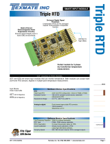
6
W
4W
PIN 1
PIN 2
PIN 3
PIN 4
PIN 5
PIN 6
PIN 7
PIN 8
SENSE -
+ EXC
+ SENSE
INPUT SIGNAL HIGH
INPUT SIGNAL LOW
- EXC
GUARD
NOT USED
263F
Programming Quick Start Guide
2
3
1
Programming Procedures
SENSOR INPUT mV/V
01 mV/V
1 2 mV/V
2 3 mV/V
3 20 mV/V
4-
5-
6-
7-
SECOND DIGIT
OUTPUT RATE
0 1 Hz averaged: 50/60 Hz rapid response
1 10 Hz averaged: 50/60 Hz rapid response
2-
3 50/60 Hz averaged: 800/960 Hz rapid response
4-
5-
6-
7-
THIRD DIGIT
FIRST DIGIT
MEASUREMENT TASK
0 Voltage, Current
1 TC (3rd digit selects
type of TC)
2 RTD 3-wire (3rd digit
selects type of RTD)
3 RTD 2- or 4-wire (3rd
digit selects type of
RTD)
4 Frequency
5Period
6 Counter
7 Smart Input Module
SECOND DIGIT
0 60 Hz rejection
1 -
2 50 Hz rejection
3 -
FIRST DIGIT
Connector PinoutsSmart Setup Registers
6-wire Bridge Configuration (for 4-wire bridge disconnect sense leads)
The meter uses three smart setup registers to configure
smart input modules . ISS1 and ISS2 requires only
smart register 1 to be set up . This module produces
six output register s. One of these registers can be
transferred to Channel 1 via Code 2, the same or anoth-
er register to Channel 2 via Code 4, the same or anoth-
er register to Channel 3 via Code 5, and the same or
another register to Channel 4 via Code 6.
This setting enters the smart register 1 code
setup menu.
This menu provides settings unique to the ISS1
input module.
Press the and buttons at the same time to
enter the main programming mode.
P
Press the button.
P
Press the button.
This takes you back to the Code 2 men u.
P
Using the buttons, reset the 3rd digit to select an output register from the
output register map.
Press the button three times to enter Code 2.
Set Code 2 to [X77].
P
Using the buttons,
select the rele vant line frequency rejection,
sensor input, and output rate settings.
4
5
6
OUTPUT REGISTER MAP
0 Averaged signal
1 Rapid response signal*
2 Peak signal*
3 Valley signal*
4 Capture signal**
5 Rate of change of signal
6-
7 Smart input module register 1 code setup
THIRD DIGIT
Note the output registers in the
3rd digit are specific to ISS1
and ISS2. These registers vary
for eac h diff erent smar t input
module.
FREQUENCY SELECT
0 10 Hz
1 10 Hz
2 100 Hz
3 100Hz
TIGER PROCESSING RATE
* Signal output at the A/D
sampling rate.
** Hardwire initiated from
meter Capture pin.
Press the and button at the same time again to re-enter the main prog ramming mode,
then press the button three times to enter Code 2.
P
P
7
Select a Channel Select the output register for the required channels

ISS1-2 Data Sheet (NZ327) Page 3Texmate, Inc. Tel. (760) 598-9899 • www.texmate.com
CH1
Set Code 2 to [X7X]. Select the required processing rate for CH1 in the 1st digit and the required
register map settings in the 3rd digit.
8
Note the output register
map is different for each
smart input module type.
OUTPUT REGISTER MAP
0 Averaged signal
1 Rapid response signal*
2 Peak signal*
3 Valley signal*
4 Capture signal**
5 Rate of change of signal
6-
7 Smart input module register 1
code setup
THIRD DIGIT
CH2
Set Code 4 to [0X0]. Select the required register map settings f or CH2 in the 2nd digit.
9
MEASUREMENT TASK
0 Voltage, Current
1 TC (type as per 2nd digit)
2 RTD (type as per 2nd digit)
3 Second Digital Input
Channel (type as per 2nd
digit)
FOR VOLTAGE & CURRENT
0 Channel 2 Disabled
1 Direct (no post processing)
2 Square Root of Channel 2
3 Inverse of Channel 2
4 Output Register 1 (smart module)*
5 Output Register 2 (smart module)*
6 Output Register 3 (smart module)*
7 Output Register 4 (smart module)*
SECOND DIGITFIRST DIGIT
*Note:
The logic f or CH2 is not the same as CH1,
CH3, or CH4. The 1st and 3rd digits must both
be set to 0.Selecting 040 to 070 in the 2nd digit
of Code 4 directly selects one of the f ollowing
settings in the output register map (3rd digit):
4 selects
5 selects
6 selects
7 selects
2nd Digit Output Register Map
0 Averaged signal
1 Rapid response signal*
2 Peak signal*
3 Valley signal*
Press the and buttons at the same
time to return to the operational display.
P
Press the button to save the settings.
P
CH3
CH4
If required enter Code 5 and select the required register map settings for CH3 in the 3rd digit.
If required enter Code 6 and select the required register map settings for CH4 in the 3rd digit.
10
11
12
FIRST DIGIT
0 Direct Display of Input (no processing)
1 Square Root of Channel 4
2 Inverse of Channel 4
3Meters with 4 kB memor y
NO Linearization
Meters with 32 kB memor y
32-point Linear ization of CH4 using
Ta ble 4
Note:
All linear ization tab les are set up in
the Calibration Mode [24X].
CH4 POST PROCESSING
Note the output register
map is different for each
smart input module type.
OUTPUT REGISTER MAP
0 Averaged signal
1 Rapid response signal*
2 Peak signal*
3 Valley signal*
4 Capture signal**
5 Rate of change of signal
6-
7 Smart input module register 1
code setup
THIRD DIGIT
FIRST DIGIT
0 Direct Display of Input (no processing)
1 Square Root of Channel 3
2 Inverse of Channel 3
3Meters with 4 kB memor y
NO Linearization
Meters with 32 kB memor y
32-point Linear ization of CH3 using
Ta ble 3
Note:
All linear ization tab les are set up in
the Calibration Mode [24X].
CH3 POST PROCESSING
FIRST DIGIT
0 10 Hz
1 10 Hz
2 100 Hz
3 100 Hz
TIGER PROCESSING RATE
* Signal output at the
A/D sampling rate.
** Hardwire initiated from
meter Capture pin.
* Signal output at the
A/D sampling rate.
** Hardwire initiated from
meter Capture pin.

ISS1-2 Data Sheet (NZ327) Page 4 Texmate, Inc. Tel. (760) 598-9899 • www.texmate.com
CODE 2
Example Load Cell Setup Procedure
For example, a 2 mV/V load cell requires maxim um signal res-
olution and minimum signal noise for a slowly varying change in
weight. Line frequency is 50 Hz. As an option, the user also
requires to monitor the raw signal.
Select a load input of 2 mV/V and a 1 Hz averaged output rate
with the averaged signal read by CH1 and the rapid response
signal read by CH3.
2
3
1Select LINE FREQ UENCY as 50 Hz f or 2 mV/V
with a 1 Hz averaged OUTPUT RATE:
In select X77 then press button.
P
SMt1 000
Set 210
Select the AVERAGED SIGNAL for CH1:
Select the RAPID RESPONSE SIGNAL for CH3:
CODE 2
In select X70
CODE 5
In select X71
Display toggles between
SMt1 to
Customer Configuration Settings:
1st Digit 2nd Digit 3rd Digit
1st Digit 2nd Digit 3rd Digit
CH3
CH4
CH2
1st Digit 2nd Digit 3rd Digit
1st Digit 2nd Digit 3rd Digit
1st Digit 2nd Digit 3rd Digit
CH1
7
7
7
00
WARRANTY
Texmate warrants that its products are free from def ects in mater ial and w orkmanship under
normal use and ser vice for a per iod of one y ear from date of shipment. Texmate’s obligations
under this warranty are limited to replacement or repair, at its option, at its factory, of any of the
products which shall, within the applicable period after shipment, be returned to Texmate’s facil-
ity, tr ansportation charges pre-paid, and which are , after e xamination, disclosed to the satis-
faction of Texmate to be thus def ective. The warranty shall not apply to an y equipment which
shall have been repaired or altered, except by Texmate, or which shall have been subjected to
misuse, negligence , or accident. In no case shall Texmate’s liability e xceed the or iginal pur-
chase price. The aforementioned provisions do not e xtend the or iginal warranty period of an y
product which has been either repaired or replaced b y Texmate.
USER’S RESPONSIBILITY
We are pleased to offer suggestions on the use of our v arious products either b y way of print-
ed matter or through direct contact with our sales/application engineering staff. However, since
we ha ve no control o ver the use of our products once the y are shipped, NO WARRANTY
WHETHER OF MERCHANT ABILITY, FITNESS FOR PURPOSE, OR O THERWISE is made
beyond the repair, replacement, or refund of purchase pr ice at the sole discretion of Texmate.
Users shall deter mine the suitability of the product f or the intended application bef ore using,
and the users assume all risk and liability whatsoever in connection therewith, regardless of any
of our suggestions or statements as to application or constr uction. In no event shall Texmate’s
liability, in law or otherwise, be in excess of the purchase pr ice of the product.
Texmate cannot assume responsibility for any circuitry described. No circuit patent or software
licenses are implied. Texmate reserves the right to change circuitry, operating software, speci-
fications, and prices without notice at any time.
For product details visit www.texmate.com
Tel: 1-760-598-9899 • USA 1-800-839-6283 • That’s 1-800-TEXMATE
Email: [email protected] • Web: www.texmate.com
1934 Kellogg Ave. • Carlsbad, CA 92008
/