Page is loading ...

IST1_IST2 (NZ358) Page 1Texmate, Inc. Tel. (760) 598-9899 • www.texmate.com
IST1 and IST2 are smart input modules that can monitor a combination of mixed temperature, process, and
counter inputs. Both modules can accept three triple 3-wire RTD sensors, two 0-10 V / 4-20 mA process
inputs, and a frequency input. Applied in multiple-point temperature measurement and automation / control
applications, these modules can be user programmed to process any four of the six inputs, or programmed
with a macro to process all six inputs.
Multiple inputs processed with powerful signal conditioning.
Hardware Module Specications
Software Module Specications
PROCESS
4 / 20 mA
1 / 5 V
FREQUENCY
RPM, Pulse, Counter
TEMPERATURE
INPUTS
3-RTD, 2-PROCESS, COUNTER INPUTS
RTD
Triple-input RTD 3-wire RTD configuration. Choice of Pt385 or Pt392.
Excitation Current 160 μA DC constant current source, ratiometric
referenced to ATD.
Resolution & Range 0.1 °C, –200 °C to +850 °C.
Process Inputs
Dual Process Inputs Bipolar, ± 88 mV full scale.
Mode Voltage or current range set by attenuation resistors.
Counter – CH1 Only
Single Counter Configured in Tiger 320 controller.
Analog-to-digital Dual channel sigma delta ATD convertor.
16-bit resolution.
Shield drive +2.5 V.
Line Frequency Rejection 50/60 Hz software selectable.
RTD Type Pt385 / Pt392 sofware selectable.
RTD Linearization On-board linearization tables for RTD.
2-point Calibration Simple 2-point calibration of RTD & process inputs
using Tiger 320 Series software.
Sampling Speed 800 / 960 Hz each channel, 20 Hz averaged outputs.
SMART INPUT MODULE
IST1 (50 Hz Rejection)
Input Module
Order Code Sux
IST2 (60 Hz Rejection)
16-pin Terminal Block.
3 RTD Inputs, 2 Process Inputs, 1 Counter Input.
IDC Shielded Cable.
In user selectable lengths.
State-of-the-art
Electromagnetic Noise
Suppression Circuitry.
Ensures signal integrity even in harsh
EMC environments.
On-board Digital Signal
Processor.
Linearization RTDs 20 Hz averaged outputs 16-bit
precision comparator function.
Interface to
Tiger Meter.

Texmate, Inc. Tel. (760) 598-9899 • www.texmate.comPage 2 IST1_IST2 (NZ358)Texmate, Inc. Tel. (760) 598-9899 • www.texmate.comPage 2
360C
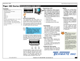
PCB 360C Smart Input Module.
Component Layout
Figure 1 – IST1/IST2 Triple RTD, Dual Process, Counter Smart Input Module
Connector Block
Interface to Sensors
See Connector Pinouts
for connection details
Connector Pinouts
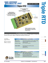
Figure 2 – IST1/IST2 to 16-pin DIN-Rail Mounted Terminal Block Connections
Input
Module
IST1
DIN-Rail
Mounted
Terminal
Block
3 M IDC Ribbon Cable
16-pin
Connectors
Interface
to Tiger
Controller
16-pin Screw
Terminal Bloc
k
Interface to
Sensors
Connecting the sensors directly to the input module is an option, but it is far easier to connect sensors via
the supplied 16-pin terminal block.
The external pinouts between the input module and the terminal block are shown in Figure 2.
1 3 5 7 9 11 1513
2 4 6 8 12 1614
1 2 3 4 5 6 7 8 9 10 11 12 13 14 15 16
RTD1+
10
RTD1–
RTD2–
RTD1 sense RTD2+
RTD3–
RTD2 sense RTD3+
+24 V Excitation
RTD3 sense
P1+
P1–
P2+
P2–
Excitation return
Counter
Shield
+24 V Excitation
RTD1 current drive
RTD1 current return
RTD1 sense / RTD2 current drive
RTD2 current return
RTD2 sense / RTD3 current drive
RTD3 current return
RTD3 current sense
External power for transducers
Process Input 1+
Process Input 1–/Exc. Return
Process Input 2+
Process Input 2–/Exc. Return
+24 V Excitation
External power/return for transducers
Counter input
Cable shield
1
2
3
4
5
6
7
8
9
10
11
12
13
14
15
16
DescriptionFunction
Input Module
Pin Numbers
RTD1+
RTD1–
RTD1 sense / RTD2+
RTD2–
RTD2 sense / RTD3+
RTD3–
RTD3 sense
+24 V Excitation
P1+
P1–
P2+
P2–
+24 V Excitation
Excitation return
Counter
Shield
1
2
3
4
5
6
7
8
9
10
11
12
13
14
15
16
Terminal Block
Pin Numbers
Attenuation Resistors
Used to set process
inputs full scale

IST1_IST2 (NZ358) Page 3Texmate, Inc. Tel. (760) 598-9899 • www.texmate.com Page 3Texmate, Inc. Tel. (760) 598-9899 • www.texmate.com
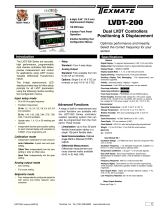
Figure 3 – Triple 3-wire RTDs connected to the terminal block in series
Example: Triple 3-wire RTD's connected to the terminal block in series.
A magnetostrictive displacement sensor having a 0-10 V output and a resistive type
displacement sensor derive their power from the input modules +24 V excitation
and set as two process inputs. The counter input is a square wave generator, likely
a flow sensor or optical pickup type also getting +24 V.
RTD1 +
RTD1 —
RTD2 —
RTD3 —
+ 24 V Exc
+ 24 V Exc
Exc Return
Counter Input
Shield
P1 +
P2 +
P1 — / Exc Return
P2 — / Exc Return
RTD1 sense / RTD2 +
RTD2 sense / RTD3 +
RTD3 sense
Magnetostrictive
Linear
Displacement
Counter Input
Resistive
Linear
Displacement
PIN 1
PIN 2
PIN 3
PIN 4
PIN 5
PIN 6
PIN7
PIN 8
PIN 9
PIN 10
PIN 11
PIN 12
PIN 13
PIN 14
PIN 15
PIN 16
+ SUPPLY
0 - 10 VOLT OUTPUT
SIGNAL GROUND
RTD+
RTD2
RTD3
— SUPPLY
16-pin DIN-Rail
Terminal Block
Overview
Example
Triple 3-wire RTDs connected to the terminal block in series.
In Figure 3, a magnetostrictive displacement sensor having a 0-10 V output and a resistive type displacement
sensor derive their power from the input module’s +24 V excitation and act as two process inputs. The counter
input is a square wave generator and is normally a flow sensor or optical pickup type also receiving +24 V.
The dual process inputs can be adapted
to voltage or current inputs by modifying
the values of thru hole attenuation resis-
tors. This is manually done in the factory
during assembly. Typically, either 0 to 10 V
or 0 to 20/40 mA are required as process
inputs. The dual process channels require
the signals to be attenuated to ±88 mV full
scale by the resistors.
Example of dual RTD with RTD3 inputs short
circuited to maintain current integrity
RTD1 +
RTD1 —
RTD2 —
RTD3 —
RTD1 sense / RTD2 +
RTD2 sense / RTD3 +
RTD3 sense
PIN 1
PIN 2
PIN 3
PIN 4
PIN 5
PIN 6
PIN7
RTD1
RTD2
RTD3 Replaced with
short-circuit wire links
16-pin DIN-Rail
Terminal Block
There are two methods of configuring the IST1/IST2 smart input module:
• By the user through the front panel using the code menus, or
• By preconfiguring the controller with a macro.
Front Panel Programming
The controller has four input channels available for processing sensor input signals when programming
through the front panel. All six sensors can be connected to the input module at the same time, but only
four can be selected and processed at any one time.
Macro Programming
With a macro installed, the controller can process all six sensor input signals at the same time. A macro
can be either pre-compiled and installed by Texmate before the module leaves the factory, or compiled
and installed by the customer. See Page 10 for a brief overview of the Tiger Macro Development System
(TDS).
A full set of tutorial documents for macro programming are available online at www.texmate.com.
Alternatively, printed copies can be sent on request.
Technical Description
Input module IST1/IST2 is designed for 3-wire RTDs that are either 100 Ω type Pt385 or Pt392. A constant
current source ratiometric referenced to a precision 16-bit ATD drives all three RTDs wired in series at the
Therefore, if only a single or dual RTD
combination is required, the unused RTD
inputs must be short circuited to ensure
the constant current loop is maintained.

Texmate, Inc. Tel. (760) 598-9899 • www.texmate.comPage 4 IST1_IST2 (NZ358)Texmate, Inc. Tel. (760) 598-9899 • www.texmate.comPage 4
Example of attenuating
0-10 V to required sig-
nal range
Example of selecting
the correct current
shunt (4 Ω) to achieve
a 0-80 mV signal corre-
sponding to a 0-20 mA
constant current input.
The input module
accepts a counter or
pulse input such as
from a paddlewheel flow
sensor or equivelant. If
this option is used, CH1
automatically defaults
as the counter input.
Smart Setup Registers
The Tiger controller uses three smart setup registers to configure all smart input modules. Line frequency rejec-
tion (50 / 60 Hz) and RTD type are configured in smart register 1 (SMT1). See Figure 5.
Smart register 1 allows you to select the following settings:
• Line frequency rejection of 50 or 60 Hz for all four sensor inputs.
• RTD type: Pt385 or Pt392 for all RTD types.
A standard sampling rate of 800 / 960 Hz (50 / 60 Hz) is applied to all inputs.
The module produces five output registers (3 RTD and 2 process), each being the 20 Hz averaged result
of the input sensors. One of these registers can be transferred to CH1 via Code 2, the same or another
register transferred to CH2 via Code 4, the same or another register transferred to CH3 via Code 5, and
the same or another register transferred to CH4 via Code 6. In addition, the module has a counter input
that is hard-wired to CH1. If the counter is required, then only channels 2, 3, and 4 are available for RTD
and process inputs.
P1+
P1–
0 to ±10 V
Full Scale
1 Megohm
8.06 k 0 to ±75 mV
Full Scale
P2+
P2–
0 to 20 mA
0 ohm
4 ohm 0 to 80 mV
Full Scale
Current
Shunt
Contact Texmate for
your required process
input type.
– 5 V
GND
+ 5 V
CH1
(Freq)
MultiplexersFiltering
Counter Input
Dual Channel
16-bit
A/TD
R
ef
Ti
g
er Mete
r
F
unctional
S
chemati
c
X3
RTD's
Dual
Process
Counter
I
2C Bus
CH 1
CH 2
+ 24 V
Exc.
Return
MUX1
EMF
EMF
EMF
MUX2
Pr
ec
i
s
io
n
+ 2.
5
V re
f
Mi
c
ro
c
ontroll
er
16-pin DIN-Rail
Terminal Block
Shield
Driver
Voltage/
Current
Voltage/
Current
Figure 4 – Input Module IST1/IST2 Functional Schematic Diagram
External +24 V excita-
tion and return is avail-
able to power external
transducers if required.

IST1_IST2 (NZ358) Page 5Texmate, Inc. Tel. (760) 598-9899 • www.texmate.com Page 5Texmate, Inc. Tel. (760) 598-9899 • www.texmate.com
RTD1 CODE 2 OUTPUT REGISTER MAP
Enter Code 2.
Select smart register 1 setup
[X77].
This allows you to enter smart
register 1 setup and configure
settings for RTD input signals.
Code 2 also allows you to
select the settings for a counter
input or frequency range for a
frequency input.
If a counter or frequency input
is used it is physically hard-
wired to CH1.
If there is no counter input,
CH1 is available for any of the
other inputs.
Code 2 allows you to select a
sensor for CH1.
SMART REGISTER 1 SETUP
SMT1 allows you to select
the line frequency between
50 or 60 Hz and select the
RTD type for all three inputs:
Pt385 or Pt392.
The output register
map is the same for
all four channels and
allows you to select
any of the three RTD
or two process inputs
for the channel you
are configuring (RTD1,
RTD2, RTD3)(Process
1, Process 2).
CH2
CH3
CH4
SMART REGISTER 3 SETUP
Not required.
SMART REGISTER 2 SETUP
Not required.
Figure 5 – IST1/IST2 Smart Setup Registers Operational Flow Diagram
CH1
Any RTD
or Process
Output
Process 1
Process 2
RTD2
RTD3
Counter
CH1
Frequency or Counter
Programming Procedures
The input module requires the following individual inputs to be programmed through the configuration
menus in the controller:
1Select Line Frequency Rejection & RTD Type
This menu allows you to select the input signal line frequency rejection for all input signals (50 or
60 Hz) and the RTD type for all RTD inputs (Pt385 or Pt392) using Smart Register 1 (SMT1).
2Setup Counter or Frequency Input
If a counter or frequency signal is used, this menu allows you to configure the frequency range or
counter settings.
3Select a Channel for the RTD or Process Input
In the code for the required channel, select the relevant RTD or process input from the output register map.
Note: If a counter or frequency signal is not used, CH1 is available for RTD or process inputs.

Texmate, Inc. Tel. (760) 598-9899 • www.texmate.comPage 6 IST1_IST2 (NZ358)Texmate, Inc. Tel. (760) 598-9899 • www.texmate.comPage 6
Select RTD Type Enter Code 2 and select the RTD type and input signal line frequency rejection setting for all inputs
2
1
MEASUREMENT TASK
0 Voltage, Current
1 TC (3rd digit selects type of TC)
2 RTD 3-wire (3rd digit selects type
of RTD)
3 RTD 2- or 4-wire (3rd digit selects
type of RTD)
4 Frequency
5 Period
6 Counter
7 Smart Input Module
SECOND DIGIT
FIRST DIGIT
This setting enters the smart register 1 code
setup menu.
Press the
P
and buttons at the same time to enter the main programming
mode.
Press the
P
button three times to enter Code 2. Set Code 2 to [X77].
The 1st digit setting is not relevant to this procedure and can remain at zero (0).
OUTPUT REGISTER MAP
0 Averaged RTD1
1 Averaged RTD2
2 Averaged RTD3
3 Averaged Process 1
4 Averaged Process 1
5 -
6 -
7 Smart input module register 1
code setup
THIRD DIGIT
0 10 Hz
1 10 Hz
2 100 Hz
3 100 Hz
TIGER PROCESSING RATE
Note: The output registers in the 3rd digit
are specific to the IST1/IST2 input module.
These registers vary for each different
smart input module.
3
NOT USED
0 -
1 -
2 -
3 -
4 -
5 -
6 -
7 -
SECOND DIGIT
RTD TYPE
0 Pt385 100 Ω
1 Pt392 100 Ω
2 -
3 -
4 -
5 -
6 -
7 -
THIRD DIGIT
FIRST DIGIT
0 60 Hz rejection
1 -
2 50 Hz rejection
3 -
This menu provides settings unique to smart
register 1 of input module IST1/IST2.
Press the
P
button.
FREQUENCY SELECT
Using the buttons,
select either 50 or 60 Hz line frequency rejection (2 for areas with 50
Hz power supplies and 0 for areas with 60 Hz power supplies) in the 1st digit and the RTD
type in the 3rd digit.
2nd digit settings are not relevant and should be left at zero (0).
4
Note: The 20 Hz averaged
signal is output for all
five inputs.
Setup Counter or Frequency Input On leaving Code 2, setup counter or frequency settings
5Press the
P
button. The display returns to [Cod_2] [X77].
6Using the buttons, set the 1st digit to the relevant processing rate, the 2nd digit to either
Frequency or Counter, and the 3rd digit to the relevant frequency range or counter setting..
Note, leaving the 3rd digit as 7 means the display constantly cycles between [Cod_2] and [SMt1].
For Frequency
For Counter
CH1 THIRD DIGIT
FIRST DIGIT
0 10 Hz
1 10 Hz
2 100 Hz
3 100 Hz
TIGER PROCESSING RATE FREQUENCY RANGE SELECTION
0 99.999 Hz range from 0.010 Hz
1 99.999 Hz range from 2.000 Hz
2 999.99 Hz range from 0.01 Hz
3 999.99 Hz range from 2.00 Hz
4 9999.9 Hz range from 0.1 Hz
5 9999.9 Hz range from 2.0 Hz
6 99 kHz range from 1 Hz (1 s gate)
7 655.35 kHz range from 10 Hz (0.1 s gate)
COUNTER
0 Counter input with 16-bit Pre-scaler
1 Setting of 16-bit Pre-scaler
2 Debounced Counter with Pre-scaler
3 Up/Down Counter with Pre-scaler
4 –
5 –
6 –
7 –
0 Voltage, Current
1 TC (3rd digit selects type of TC)
2 RTD/Resistance 3-wire (3rd digit
selects type of RTD)
3 RTD/Resistance 2- or 4-wire (3rd
digit selects type of RTD)
4 Frequency
5 Period
6 Counter
7 Smart Input Module
SECOND DIGIT
MEASUREMENT TASK
Frequency
Counter
OR
Press the
P
and buttons at the same time to return to the operational display.
7

IST1_IST2 (NZ358) Page 7Texmate, Inc. Tel. (760) 598-9899 • www.texmate.com Page 7Texmate, Inc. Tel. (760) 598-9899 • www.texmate.com
9
Press the
P
and buttons at the same time again to re-enter the main programming mode, then
press the
P
button three times to enter Code 2.
8
Select a Channel Select a channel for the RTD or process input from the output register map of the required channel
Channel 1
If a counter or frequency input has not been applied to CH1, then this channel is still available for an RTD
or process input signal. To select an RTD or process signal for CH1:
CH1
Note: The output register
map is different for each
smart input module type.
Set Code 2 to [X7X]. Select the required processing rate for all input sensors in the 1st digit and
the required RTD or process signal in the 3rd digit.
0 10 Hz
1 10 Hz
2 100 Hz
3 100Hz
FIRST DIGIT
TIGER PROCESSING RATE MEASUREMENT TASK
0 Voltage, Current
1 TC (3rd digit selects type of TC)
2 RTD 3-wire (3rd digit selects type of RTD)
3 RTD 2- or 4-wire (3rd digit selects type of RTD)
4 Frequency
5 Period
6 Counter
7 Smart Input Module
SECOND DIGIT
OUTPUT REGISTER MAP
0 Averaged RTD1
1 Averaged RTD2
2 Averaged RTD3
3 Averaged Process 1
4 Averaged Process 2
5 -
6 -
7 Smart input module register 1
code setup
THIRD DIGIT
Channel 2
*Note:
The logic for CH2 is not the same as CH1,
CH3, or CH4. The 1st and 3rd digits must
both be set to 0. Selecting 040 to 070 in the
2nd digit of Code 4 directly selects one of the
following settings in the output register map
(3rd digit):
CH2
Enter Code 4 and set to [0X0]. Select the required register map settings for CH2 in the 2nd digit. See *Note in 2nd digit below.
10
MEASUREMENT TASK
0 Voltage, Current
1 TC (type as per 2nd digit)
2 RTD (type as per 2nd digit)
3 Second Digital Input
Channel (type as per 2nd
digit)
FOR VOLTAGE & CURRENT
0 Channel 2 Disabled
1 Direct (no post processing)
2 Square Root of Channel 2
3 Inverse of Channel 2
4 Output Register 1 (smart module)*
5 Output Register 2 (smart module)*
6 Output Register 3 (smart module)*
7 Output Register 4 (smart module)*
SECOND DIGITFIRST DIGIT
4 selects
5 selects
6 selects
7 selects
2nd Digit
Output Register Map
0 Averaged RTD1
1 Averaged RTD2
2 Averaged RTD3
3 Averaged Process 1
Channel 3
Press the
P
and buttons at
the same t i m e to return to
the operational display.
Press the
P
button to save the
settings.
CH3
CH4
Enter Code 5 and select the required register map settings for CH3 in the 3rd digit.
Enter Code 6 and select the required register map settings for CH4 in the 3rd digit.
11
12
13
FIRST DIGIT
0 Direct Display of Input (no processing)
1 Square Root of Channel 4
2 Inverse of Channel 4
3 Meters with 4 kB memory
NO Linearization
Meters with 32 kB memory
32-point Linearization of CH4 using Table 4
Note:
All linearization tables are set up in the Calibration Mode [24X].
CH4 POST PROCESSING
Note: The output register
map is different for each
smart input module type.
OUTPUT REGISTER MAP
0 Averaged RTD1
1 Averaged RTD2
2 Averaged RTD3
3 Averaged Process 1
4 Averaged Process 2
5 -
6 -
7 Smart input module register 1 code setup
THIRD DIGIT
FIRST DIGIT
0 Direct Display of Input (no processing)
1 Square Root of Channel 3
2 Inverse of Channel 3
3 Meters with 4 kB memory
NO Linearization
Meters with 32 kB memory
32-point Linearization of CH3 using Table 3
Note:
All linearization tables are set up in the Calibration Mode [24X].
CH3 POST PROCESSING
Channel 4
14
Note: Unlike CH1, you
cannot select Averaged
Process 2 in CH2.

Texmate, Inc. Tel. (760) 598-9899 • www.texmate.comPage 8 IST1_IST2 (NZ358)Texmate, Inc. Tel. (760) 598-9899 • www.texmate.comPage 8
Example 1:
User Programmable
Application
Example 1 describes the setup procedure for measuring the volume, temperature, and flow rate of a milk
vat using front panel programming.
The volume of the milk vat is monitored using a linear displacement transducer and float arrangement. A
pump transfers the milk past a flow rate sensor. The milk vat temperature and discharge temperature are
monitored using type Pt392 RTD sensors.
The input module is wired via the 16-pin DIN-rail mounted terminal block. See Figure 7 for connection
details between the terminal block and the input sensors. The inputs are designated to the following chan-
nels:
• CH1: Flow rate sensor – Frequency input.
• CH2: Milk vat temperature – RTD2 input.
• CH3: Discharge temperature – RTD3 input.
• CH4: Milk volume – Process 1 input.
The input module is wired via the DIN terminal block, so that Tiger Channel designation:
The volume of a milk vat is monitored using a linear displacement
transducer and float arrangement.
A pump transfers the milk past a flow rate sensor. The milk vat
temperature and discharge temperature are monitored using Pt
392 RTD sensors.
Milk Volume Application
Example
Note: RTD 1 is not used, neither is Process 2 Input and the frequency input
automaticaly defaults to CH 1 if it is required.
CH 1 Flow Rate Sensor Frequency Input.
CH 2 Milk Vat Temperature RTD 2 Input.
CH 3 Discharge Temperature RTD 3 Input.
CH 4 Milk Volume Process 1 Input.
Tiger 320 Series Controller
SP1 SP2 SP3 SP4 SP5 SP6
Prog.
DI-50 TIGER 320 SERIES
Pump
RTD3
RTD2
Milk Vat
Float
Magnetostrictive
Displacement
Sensor
Milk
Volume
CH4
Flow
Rate
CH1
Discharge
Temp.
CH3
Vat
Temp
CH2
All Input Signals
loaded via
16-PIN TERMINAL BLOCK
MILK
Outlet
Valve
Figure 6 – Example 1: Using IST1/IST2 in a User Programmable Application
Note: RTD1 is not used. Process
input 2 is not used. The frequency
input automatically defaults to CH1.
Note: As RTD1 is not used, Pins 1, 2 & 3 are shorted together.
Both the linear displacement transducer and the flow rate sensor take their
excitation voltage (+24 V) from the input module.
Process input 2 is not used so it remains unconnected.
RTD 1 +
RTD 1 —
RTD 2 —
RTD 3 —
+ 24 V Exc
+ 24 V Exc
Exc Return
Counter Input
Shield for Cable
P1 +
P2 +
P1 — / Exc Return
P2 — / Exc Return
RTD 1 sense / RTD 2 +
RTD 2 sense / RTD 3 +
RTD 3 sense
Flow
Rate
Sensor
MILK
Terminal Block Wiring
PIN 1
PIN 2
PIN 3
PIN 4
PIN 5
PIN 6
PIN7
PIN 8
PIN 9
PIN 10
PIN 11
PIN 12
PIN 13
PIN 14
PIN 15
PIN 16
+ SUPPLY
Discharge
Temp
Sensor
Milk Vat
Temp
Sensor
+ SUPPLY
SIGNAL
SIGNAL GND
N/C
N/C
N/C
RTD2
RTD3
— SUPPLY
— SUPPLY
Signal Pulses / Rev
Displacement
Magnetostrictive
Sensor
16-PIN DIN-Rail Terminal Block
Figure 7 – Example 1: Application Wiring of Sensor Inputs to 16-pin Terminal Block
Note: RTD1 is not used, pins 1, 2, and
3 are shorted together. Both the linear
displacement transducer and the flow
rate sensor take their excitation volt-
age (+24 V) from the input module. As
process input 2 is not used it remains
unconnected.

IST1_IST2 (NZ358) Page 9Texmate, Inc. Tel. (760) 598-9899 • www.texmate.com Page 9Texmate, Inc. Tel. (760) 598-9899 • www.texmate.com
Example 1 Setup Procedure
1Select 50 Hz input line frequency rejection with Pt392 RTDs.
The averaged output rate of 20 Hz for all sensor inputs is more than adequate for fast
filling / draining of the milk vat:
CODE 2
CODE 2
In select X43 then press
P
button three times.
2Select CH1 frequency input of 2 Hz - 1000 Hz for the flow rate sensor:
In reset to X77 then press
P
button.
3Select RTD2 as the vat temperature input for CH2:
CODE 4
In select 050
SMt1 000
Display toggles between
Set 301
SMt1 to
4Select RTD3 as the discharge temperature input for CH3:
CODE 5
In select 072
5Select process input 1 as the milk volume input for CH4:
CODE 6
In select X73
Note: both RTD inputs (RTD2 and RTD3) and the linear displacement
transducer input (Process Input 1) require to be individually calibrat-
ed using the controller’s 2-point calibration technique.
Example 2:
Application Running a
Macro
The IST1 and the IST2 have 5 active smart output registers available. Access to the fifth register (or all
registers) can be done through a simple macro string as demonstrated in the example macro below.
First set Code 7 to [000] so that the Result register (& Result) is not updated by any math function. In
the example macro below the Main Macro defines the Result register as the 5th smart output register
(&SMART_RESULT5). In this way CH1 to CH4 contain the first four smart output registers and the Result
contains the fifth.
Macros are powerful tools used to increase the versatility and range of the Tiger controller beyond the
standard code settings. For further information on macros and the registers in the Tiger 320 operating
system see the following literature:
• TDS Macro Tutorial (NZ212).
• Registers Supplement (NZ209).
These and other Tiger related documents are freely available on our website at:
www.texmate.com

Texmate, Inc. Tel. (760) 598-9899 • www.texmate.comPage 10 IST1_IST2 (NZ358)Texmate, Inc. Tel. (760) 598-9899 • www.texmate.comPage 10
RTD Full Scale
Calibration Procedures
The RTDs can be calibrated in °F or °C. Using a calibration source to calibrate a zero and full scale setting
is the easiest method to use. If a calibration source is not available, the known resistance values for the
temperatures can be used.
The following table lists the equivelant resistances for both Pt385 and Pt392 type 100 Ω RTDs over a
temperature range of 0 to 100 °C.
RTD Type Temperature
Type Pt385 / 392
Type Pt385
Type Pt392
Equivelant Resistance
0 °C
100 °C
100 °C
100 Ω
138.5 Ω
139.3 Ω
PIN 1
PIN 2
PIN 3
PIN 4
PIN 5
PIN 6
PIN7
16-PIN DIN-Rail
Terminal Block
100 ohm
RTD1
RTD2
RTD3
100 ohm
100 ohm
SP1 SP2 SP3 SP4 SP5 SP6
Prog.
Resistor Connections for Zero (low) Setting
Example 2-point Calibration Procedure
The example 2-point calibration procedure on Page 11 can be used with a calibration source or with the
calibration plug method. Enter the calibration mode and carry out the 2-point calibration procedure on the
first channel required for RTD input.
Repeat this procedure for any other channels requiring an RTD input.
If a calibration source is not avail-
able make up a set of calibration
plugs with the resistors shown in
the diagrams opposite.
Plug the 0 °C calibration plug
into the module and program the
[ZEro] setting for the first channel
required.
Unplug the 0 °C plug and plug the
100 °C calibration plug into the
module and program the [SPAn]
setting for the same channel.
PIN 1
PIN 2
PIN 3
PIN 4
PIN 5
PIN 6
PIN7
16-PIN DIN-Rail
Terminal Block
138.5 ohm
(139 ohm)
RTD1
RTD2
RTD3
SP1 SP2 SP3 SP4 SP5 SP6
Prog.
138.5 ohm
(139 ohm)
138.5 ohm
(139 ohm)
Resistor Connections for Span (high) Setting
Tiger Macro Development
System (TDS)
Tiger 320 Macro Overview
The Tiger 320 Series of programmable meter controllers have been designed to incorporate the
analog and digital functionality of an intelligent controller with the logic of a PLC.
Traditionally, the PLC approach is to build a working application entirely in some form of pro-
gramming language. The approach used in the Tiger 320 Series of controllers is to build an
application by selecting the pre-programmed functions of the controller and then adding small
amounts of programmability and logic where needed.
The operating system of the Tiger 320 controller controls all the pre-programmed functions,
handling the input, averaging, scaling, linearization, totalization and much more, as well as driv-
ing the display, timers, relays, analog and serial outputs. Once configured, these functions are
executed by the operating system and form the basis of a control system.
To form an advanced automation and control system you only need to write a small program
that adds the extra logic required. We call this program a macro. A macro can be written specifi-
cally for your application and is used to initiate a sequence, reconfigure, or disable some of the
controller functions. With Texmate's 22 I/O plug-in module installed, a macro further expands the
Tiger 320 operating system with additional digital status inputs and digital switched outputs.

IST1_IST2 (NZ358) Page 11Texmate, Inc. Tel. (760) 598-9899 • www.texmate.com Page 11Texmate, Inc. Tel. (760) 598-9899 • www.texmate.com
Prog.
SP1 SP2 SP4SP3 SP5 SP6
TEXMATE
Prog.
SP1 SP2 SP4SP3 SP5 SP6
TEXMATE
Prog.
SP1 SP2 SP4SP3 SP5 SP6
TEXMATE
Prog.
SP1 SP2 SP4SP3 SP5 SP6
TEXMATE
Prog.
SP1 SP2 SP4SP3 SP5 SP6
TEXMATE
Prog.
SP1 SP2 SP4SP3 SP5 SP6
TEXMATE
Prog.
SP1 SP2 SP4SP3 SP5 SP6
TEXMATE
Prog.
SP1 SP2 SP4SP3 SP5 SP6
TEXMATE
Prog.
SP1 SP2 SP4SP3 SP5 SP6
TEXMATE
Prog.
SP1 SP2 SP4SP3 SP5 SP6
TEXMATE
Prog.
SP1 SP2 SP4SP3 SP5 SP6
TEXMATE
Prog.
SP1 SP2 SP4SP3 SP5 SP6
TEXMATE
Prog.
SP1 SP2 SP4SP3 SP5 SP6
TEXMATE
Prog.
SP1 SP2 SP4SP3 SP5 SP6
TEXMATE
Prog.
SP1 SP2 SP4SP3 SP5 SP6
TEXMATE
X
Prog.
SP1 SP2 SP4SP3 SP5 SP6
TEXMATE
Prog.
SP1 SP2 SP4SP3 SP5 SP6
TEXMATE
To Step 7
OR
From Step 6
5.2. Apply the LOW
input signal, or connect
the 0 °C plug to the
module
OR
OR
Press
1
Press
1
Press
1
Press
1
Press
at same
time
Press
at same
time
Press
at same
time
Press
at same
time
Step 1
Step 2
Step 3
Step 4
Step 5
Step 6
7.2. Apply the HIGH
input signal, or connect
the 100 °C plug to the
module
Step 7
Step 8
Step 9
Step 10
Step 11
Enter the
brightness
mode
Pass the brightness
mode and the enter
calibration mode
Select the no function
calibration mode [000]
Save calibration mode
[000] setting and enter
Code 1
Operational Display
Operational Display
Exit Code 1 and return
to the operational display
Enter calibration
mode [111] for 2-point
calibration of CH1
5.1. Adjust display to
desired reading for
zero input
7.1. Adjust display to
desired reading for
span input
Set reading for zero
load into meter and
enter span mode
Save zero and span
settings and re-enter
calibration mode
Example
Example
OR
LOW
Signal
HIGH
Signal
2-point Cal.eps
Set calibration mode to [111]:
1st Digit = 1
Selects calibration procedures
2nd Digit = 1
Selects 2-point calibration
3rd Digit = 1
Selects CH1 for calibration
Prog.
SP1 SP2 SP4SP3 SP5 SP6
TEXMATE
Press
1
[111] for CH1
[112] for CH2
[113] for CH3
[114] for CH4
2-point Calibration
Mode Example
START HERE
Macro control is ideal for many OEM applications that require analog, digital, and timer func-
tions with sophisticated mathematical and enhanced logic operations. The macro concept has
major cost advantages for large or small sophisticated applications that require some degree of
programmable logic control with display and front panel control.
Custom Macro Programming
Texmate’s Tiger Development System (TDS) enables a macro to be written and compiled
in BASIC, utilizing any combination of the hundreds of functions and thousands of registers
embedded in the Tiger 320 Operating System. When your BASIC program is compiled into Tiger
320 Macro-language it is error checked and optimized.

Texmate, Inc. Tel. (760) 598-9899 • www.texmate.comPage 12 IST1_IST2 (NZ358)Texmate, Inc. Tel. (760) 598-9899 • www.texmate.comPage 12
Customer Configuration Settings:
1st Digit 2nd Digit 3rd Digit
1st Digit 2nd Digit 3rd Digit
CH3
CH4
CH2
1st Digit 2nd Digit 3rd Digit
1st Digit 2nd Digit 3rd Digit
1st Digit 2nd Digit 3rd Digit
CH1
7
7
00
WARRANTY
Texmate warrants that its products are free from defects in material and workmanship under
normal use and service for a period of one year from date of shipment. Texmate’s obligations
under this warranty are limited to replacement or repair, at its option, at its factory, of any of
the products which shall, within the applicable period after shipment, be returned to Texmate’s
facility, transportation charges pre-paid, and which are, after examination, disclosed to the sat-
isfaction of Texmate to be thus defective. The warranty shall not apply to any equipment which
shall have been repaired or altered, except by Texmate, or which shall have been subjected
to misuse, negligence, or accident. In no case shall Texmate’s liability exceed the original pur-
chase price. The aforementioned provisions do not extend the original warranty period of any
product which has been either repaired or replaced by Texmate.
USER’S RESPONSIBILITY
We are pleased to offer suggestions on the use of our various products either by way of printed
matter or through direct contact with our sales/application engineering staff. However, since
we have no control over the use of our products once they are shipped, NO WARRANTY
WHETHER OF MERCHANTABILITY, FITNESS FOR PURPOSE, OR OTHERWISE is made
beyond the repair, replacement, or refund of purchase price at the sole discretion of Texmate.
Users shall determine the suitability of the product for the intended application before using,
and the users assume all risk and liability whatsoever in connection therewith, regardless of any
of our suggestions or statements as to application or construction. In no event shall Texmate’s
liability, in law or otherwise, be in excess of the purchase price of the product.
Texmate cannot assume responsibility for any circuitry described. No circuit patent or software
licenses are implied. Texmate reserves the right to change circuitry, operating software, speci-
fications, and prices without notice at any time.
For product details visit www.texmate.com
Tel: 1-760-598-9899 • USA 1-800-839-6283 • That’s 1-800-TEXMATE
Alphanumeric Displays
14-segment alphanumeric displays are Texmate’s display choice for easy to read display text and scrolling
text messaging.
SP1 SP2 SP4
SP3 SP5 SP6
or
or
or for "slow" as:
For "tank low" as:
7-SEGMENT 14-SEGMENT
Macros are useful when implementing a specialized control system that cannot be achieved
by the standard configuration capability of the Tiger 320 Operating System. Using the TDS
software, functions can be altered or added in a standard controller to perform the required job.
This may typically include logic sequencing functions and mathematical functions.
Developing a Macro is much easier and quicker than programming a PLC, because the
basic code required to customize the Tiger meter is considerably less than the ladder logic
programming required for PLCs. This is due to the hundreds of functions built into the Tiger
controller that can be manipulated or invoked by a macro to fulfill the requirements of almost
any application.
Scrolling display messages can be programmed to appear with any setpoint activation, select-
ed event, or logic input. Easy to read, plain text prompts can be programmed to replace the
manual programming codes and provide a user-friendly interface for any custom application.
Scrolling Text Messaging
Scrolling text messaging is another bonus from running a macro. Any number of messages
for detailed operator instructions, of up to 100 characters each, can be written into the macro
during compilation for detailed operator instructions, alarm and control applications.
A scrolling text message can be written for OEMs and sensor manufacturers providing infor-
mative instructions for setup and calibration procedures.
1934 Kellogg Ave. • Carlsbad, CA 92008
Email: [email protected] • Web: www.texmate.com
/