Page is loading ...

ISSA Data Sheet (NZ354) Page 1Texmate, Inc. Tel. (760) 598-9899 • www.texmate.com
Quad inputs, complete with excitation voltage and accurate ratiometric sensing of slider or rotative position, deliver
multiple axis linear displacement sensing or similar resistive measurements. Designed to interface with Tiger 320
Series controllers, the ISSA provides the capacity for accurate and continuous process control and feedback
systems.
Adding 4 dimensions to linear or rotative displacement registration.
Hardware Module Specifications
Software Module Specifications
SMART QUAD
RESISTIVE
DISPLACEMENT
INPUTS
QUAD RESISTIVE DISPLACEMENT SENSOR
Output Rates 1, 5, 10, 20, or 50/60 Hz output rate for all channels.
Gain Select Optimized for +2.5 V excitation.
Line Frequency Rejection 50/60 Hz software selectable.
Excitation Voltage Independent +2.5 V excitation (10 mA).
Resistance Range 1 kilohm to 100 kilohm (typical).
A/D Converter Quad channel ultra-low-noise 16-bit ATD with
effective 19-bit resolution in post processing software.
Input Sensitivity 5 µV / count full scale maximum.
Zero Drift ± 40 µV / °C typical.
Span Drift ± 5 ppm / °C of full scale maximum.
Non-linearity ± 0.003% of full scale maximum.
Input Noise 30 µV p-p typical at 1 Hz output rate.
Potentiometer Inputs Quad, ratiometric referenced to ATD.
Resolution 1:100,000 counts of full scale (+2.5 V).
ISSA
Input Module
Order Code Suffix
Fits Tiger 320 Series
Interface to Tiger Meter.
State-of-the-art Electromagnetic
Noise Suppression Circuitry.
Ensures signal integrity even in harsh
EMC environments.
On-board Digital Signal Processor.
Choice of averaging and sample rates.
4 Averaged outputs.
Ultra low-noise 16-bit SD Dual
Channel ATD.
Ratiometric operation.
Approaching 19-bit performance
with additional software filtering.
11-pin Input Connector.
Quad 3-wire Pot inputs &
+2.5VDC Excitation.
Crystal Controlled Line
Frequency Rejection.
50 / 60Hz line frequency rejection.

Texmate, Inc. Tel. (760) 598-9899 • www.texmate.comPage 2 ISSA Data Sheet (NZ354)
372
LINEAR
DISPLACEMENT
TRANSDUCERS
INCREASING SIGNAL
INCREASING SIGNAL
INCREASING SIGNAL
INCREASING SIGNAL
Pot 1
Pot 2
Pot 3
Pot 4
PIN 1
PIN 2
PIN 3
PIN 4
PIN 5
PIN 6
PIN 7
PIN 8
PIN 9
PIN 10
PIN 11
372
Connector Pinouts
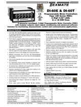
Figure 1 – ISSA Quad 3-wire Potentiometer Smart Input Module
Quad 3-wire Potentiometer Smart Module con-
nected to four linear displacement transducers.
Input Signal 1 (Pot 1)
CODE 2 SMART REGISTER 1 SETUP OUTPUT REGISTER MAP
Enter Code 2.
Select smart register 1 setup [X77].
This allows you to enter smart regis-
ter 1 setup and configure settings f or
input signals 1, 2, 3, 4.
SMT1 allo ws y ou to select
the line frequency betw een
50 or 60 Hz and select the
output r ate f or input signals
1, 2, 3, 4.
The output register map
allows you to select an y
of the f our potentiome-
ter outputs (Pot 1, Pot 2,
Pot 3, P ot 4) f or an y of
the controller channels
(CH1, CH2, CH3, CH4).
CH2
CH3
CH4
SMART REGISTER 3 SETUP
Not required.
SMART REGISTER 2 SETUP
Not required.
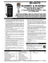
Figure 2 – ISSA Smar t Setup Registers Operational Flow Diagram
Smart Setup Registers
The Tiger meter uses three smart setup registers to configure all smar t input modules. The line frequency rejec-
tion (50 / 60 Hz) and the a veraged output rate are configured in smart register 1 (SMT1). See Figure 2.
Potentiometer signals, Pot 1, Pot 2, Pot 3, and Pot 4, are then individually software selected for the four input
channels. Either signal can be selected f or CH1 via Code 2, CH2 via Code 4, CH3 via Code 5, and CH4
via Code 6. Note, two signals cannot be selected for the same channel.
CH1
Programming Procedures
The following programming procedures cover all the steps required to configure smart input module ISSA.
Steps 1to 5describe how to select the line frequency and the output rate through SMT1.
Steps 7to 12 describe how to select the output registers f or channels 1, 2, 3, or 4 as required.
Pot 1
Pot 2
Programming Quick Start Guide
2
1
MEASUREMENT TASK
0 Voltage, Current
1 TC (3rd digit selects type of TC)
2 RTD 3-wire (3rd digit selects type
of RTD)
3 RTD 2- or 4-wire (3rd digit selects
type of RTD)
4 Frequency
5Period
6 Counter
7 Smart Input Module
SECOND DIGITFIRST DIGIT
This setting enters the smart register 1 code
setup menu.
Press the and buttons at the same time to enter the main programming mode.
P
Press the button three times to enter Code 2. Set Code 2 to [X77].
P
OUTPUT REGISTER MAP
0 Averaged Pot 1
1 Averaged Pot 2
2 Averaged Pot 3
3 Averaged Pot 4
4-
5-
6-
7 Smart input module register 1
code setup
THIRD DIGIT
0 10 Hz
1 10 Hz
2 100 Hz
3 100 Hz
TIGER PROCESSING RATE
Note the output registers in the 3rd digit are
specific to the Quad 3-wire Potentiometer
input module. These registers vary for each
different smart input module.
Input Signal 2 (Pot 2)
Input Signal 3 (Pot 3)
Input Signal 4 (Pot 4)
Pot 3
Pot 4

ISSA Data Sheet (NZ354) Page 3Texmate, Inc. Tel. (760) 598-9899 • www.texmate.com
*Note:
The logic f or CH2 is not the same as CH1,
CH3, or CH4. The 1st and 3rd digits must both
be set to 0.Selecting 040 or 050 in the 2nd digit
of Code 4 directly selects one of the f ollowing
settings in the output register map (3rd digit):
3
NOT USED
0-
1-
2-
3-
4-
5-
6-
7-
SECOND DIGIT
OUTPUT RATE
0 1 Hz averaged, 50 / 60 Hz sample
1 5 Hz averaged, 100 / 120 Hz sample
2 10 Hz averaged, 400 / 480 Hz sample
3 20 Hz averaged, 800 / 960 Hz sample
4 50 / 60 Hz averaged, 1600/1920 Hz sample
5-
6-
7-
THIRD DIGIT
FIRST DIGIT
0 -
1 60 Hz rejection
2 -
3 50 Hz rejection
This men u pro vides settings unique to smart
register 1 of input module ISSA.
Press the button.
P
Using the buttons,
select either 50 or 60 Hz line frequency rejection in the
1st digit and the output rate common to all four input signals in the 3rd digit.
2nd digit settings are not relevant and should be left at z ero (0).
4
FREQUENCY SELECT
5Press the button. The display returns to [Cod_2] [X77].
P
6Using the button, reset the 3rd digit to z ero [X70] to leave the smart register 1 menu.
Note, leaving the 3rd digit as 7 means the displa y constantly cycles between [Cod_2] and [SMt1].
CH1
Set Code 2 to [X7X]. Select the required processing rate for CH1 in the 1st digit and the required
register map settings in the 3rd digit.
2nd digit settings are not relevant and should be left at z ero (0).
9
Note the output register
map is different for each
smart input module type.
OUTPUT REGISTER MAP
0 Average Pot 1
1 Average Pot 2
2 Average Pot 3
3 Average Pot 4
4-
5-
6-
7 Smart input module register 1
code setup
THIRD DIGIT
CH2
Set Code 4 to [0X0]. Select the required register map settings f or CH2 in the 2nd digit.
10
MEASUREMENT TASK
0 Voltage, Current
1-
2-
3-
FOR VOLTAGE & CURRENT
0 Channel 2 Disabled
1 Direct (no post processing)
2 Square Root of Channel 2
3 Inverse of Channel 2
4 Output Register 1 (smart module)*
5 Output Register 2 (smart module)*
6 Output Register 3 (smart module)*
7 Output Register 4 (smart module)*
SECOND DIGITFIRST DIGIT
4 selects
5 selects
6 selects
7 selects
2nd Digit Output Register Map
0 Averaged Pot 1
1 Averaged Pot 2
2 Averaged Pot 3
3 Averaged Pot 4
FIRST DIGIT
0 10 Hz
1 10 Hz
2 100 Hz
3 100 Hz
TIGER PROCESSING RATE
Press the and buttons at the same time again to re-enter the main prog ramming mode,
then press the button three times to enter Code 2.
P
P
8
Select a Channel Select the output register for the required channels
Press the and buttons at the same time to retur n to the operational display.
P
7

Texmate, Inc. Tel. (760) 598-9899 • www.texmate.comPage 4 ISSA Data Sheet (NZ354)
Press the and buttons at the same
time to return to the operational display.
P
Press the button to save the settings.
P
CH3
CH4
Enter Code 5 and select the required output register map settings f or CH3 in the 3rd digit.
Enter Code 6 and select the required output register map settings f or CH4 in the 3rd digit.
11
12
13
FIRST DIGIT
0 Direct Display of Input (no processing)
1 Square Root of Channel 4
2 Inverse of Channel 4
3Meters with 4 kB memor y
NO Linearization
Meters with 32 kB memor y
32-point Linear ization of CH4 using
Ta bl e 4
Note:
All linear ization tab les are set up in
the Calibration Mode [24X].
CH4 POST PROCESSING
Note the output register
map is different for each
smart input module type.
OUTPUT REGISTER MAP
0 Average Pot 1
1 Average Pot 2
2 Average Pot 3
3 Average Pot 4
4-
5-
6-
7 Smart input module register 1
code setup
THIRD DIGIT
FIRST DIGIT
0 Direct Display of Input (no processing)
1 Square Root of Channel 3
2 Inverse of Channel 3
3Meters with 4 kB memor y
NO Linearization
Meters with 32 kB memor y
32-point Linear ization of CH3 using
Ta bl e 3
Note:
All linear ization tab les are set up in
the Calibration Mode [24X].
CH3 POST PROCESSING
Customer Configuration Settings:
1st Digit 2nd Digit 3rd Digit
1st Digit 2nd Digit 3rd Digit
CH3
CH4
CH2
1st Digit 2nd Digit 3rd Digit
1st Digit 2nd Digit 3rd Digit
1st Digit 2nd Digit 3rd Digit
CH1
7
7
00
WARRANTY
Texmate warrants that its products are free from def ects in mater ial and w orkmanship under
normal use and ser vice for a per iod of one y ear from date of shipment. Texmate’s obligations
under this warranty are limited to replacement or repair, at its option, at its factory, of any of the
products which shall, within the applicable period after shipment, be returned to Texmate’s facil-
ity, tr ansportation charges pre-paid, and which are , after e xamination, disclosed to the satis-
faction of Texmate to be thus def ective. The warranty shall not apply to an y equipment which
shall have been repaired or altered, except by Texmate, or which shall have been subjected to
misuse, negligence , or accident. In no case shall Texmate’s liability e xceed the or iginal pur-
chase price. The aforementioned provisions do not e xtend the or iginal warranty period of an y
product which has been either repaired or replaced b y Texmate.
USER’S RESPONSIBILITY
We are pleased to offer suggestions on the use of our v arious products either by way of print-
ed matter or through direct contact with our sales/application engineering staff. However, since
we ha ve no control o ver the use of our products once the y are shipped, NO WARRANTY
WHETHER OF MERCHANT ABILITY, FITNESS FOR PURPOSE, OR O THERWISE is made
beyond the repair, replacement, or refund of purchase pr ice at the sole discretion of Texmate.
Users shall deter mine the suitability of the product f or the intended application bef ore using,
and the users assume all risk and liability whatsoever in connection therewith, regardless of any
of our suggestions or statements as to application or constr uction. In no event shall Texmate’s
liability, in law or otherwise, be in excess of the purchase pr ice of the product.
Texmate cannot assume responsibility for any circuitry described. No circuit patent or software
licenses are implied. Texmate reserves the right to change circuitry, operating software, speci-
fications, and prices without notice at any time.
For product details visit www.texmate.com
Tel: 1-760-598-9899 • USA 1-800-839-6283 • That’s 1-800-TEXMATE
Email: [email protected] • Web: www.texmate.com
1934 Kellogg Ave. • Carlsbad, CA 92008
/