Page is loading ...

IST3-4 Data Sheet (NZ362) Page 1Texmate, Inc. Tel. (760) 598-9899 • www.texmate.com
Ideal for multi-temperature control systems, IST3 and IST4 monitor up to four individual thermocouple
sensors at 10 Hz averaged output rate. A choice of industry J or K type thermocouples with an on-board
temperature sensor for reference junction compensation provide a versatile interface for temperature
measurement tasks.
Multiple inputs processed with powerful signal conditioning.
Hardware Module Specifications
Software Module Specifications
TEMPERATURE
INPUTS
QUAD THERMOCOUPLE INPUT
Input Channels Four independent channels, zero X-talk and
16-bit resolution.
Thermocouple Type Industry standard J or K type (software selectable).
Input Sensitivity 0.08 µV / count maximum.
Zero Drift ±40 nV / °C typical.
Span Drift ±5 ppm / °C full scale maximum.
Non-linearity ±0.003% 5of full scale maximum.
Input Noise 160 nV p-p typical.
Signal Processing Rate 10 Hz averaged output rate on all channels.
Reference Junction On-board solid state sensor referenced thermal connection
to terminal block socket. Resolution better that 0.1 °C.
Output Rate Fixed 10 Hz averaged per channel.
Sensor Selection Choice of J or K, software selectable.
Line Frequency Rejection 50/60 Hz, software selectable.
Broken Thermocouple [OVER] on display indicates broken thermocouple.
Software senses a broken thermocouple and causes
the display to flash [OVER]. Note, only seen if that display
is the current display. Otherwise, it can be checked through
the view mode.
Fits Tiger 320 Series
IST3 (50 Hz Rejection)
IST4 (60 Hz Rejection)
Input Module
Order Code Suffix
Interface to Tiger Meter.
Crystal Controlled Line
Frequency Rejection.
50 / 60Hz line frequency rejection.
8-pin Input Connector.
Quad J or K Thermocouple.
Terminal Reference Junction.
On-board Reference Junction Sensor.
State-of-the-art Electromagnetic Noise
Suppression Circuitry.
Ensures signal integrity even in harsh EMC
environments.
On-board Digital Signal Processor.
Choice of type J or K thermocouples.
10Hz Averaged output.

Texmate, Inc. Tel. (760) 598-9899 • www.texmate.comPage 2 IST3-4 Data Sheet (NZ362)
381
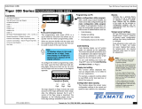
TC1 +
TC1 –
TC2 +
TC2 –
TC3 +
TC3 –
TC4 +
TC4 –
TC4
PIN 1
PIN 2
PIN 3
PIN 4
PIN 5
PIN 6
PIN 7
PIN 8
TC3
TC2
TC1
Connector Pinouts
Figure 1 – IST3/IST4 Quad Thermocouple Smart Input Module
Input Signal 1 (TC1)
CODE 2 SMART REGISTER 1 SETUP OUTPUT REGISTER MAP
Enter Code 2.
Select smart register 1 setup [X77].
This allows you to enter smart regis-
ter 1 setup and configure settings f or
input signals 1, 2, 3, 4.
SMT1 allo ws y ou to select
either 50 or 60 Hz line fre-
quency and select the ther-
mocouple type f or all f our
inputs: J or K.
The output register map
allows you to select an y
of the four thermocouple
inputs (TC1, TC2, TC3,
TC4) for any of the con-
troller channels (CH1,
CH2, CH3, CH4).
CH2
CH3
CH4
SMART REGISTER 3 SETUP
Not required.
SMART REGISTER 2 SETUP
Not required.
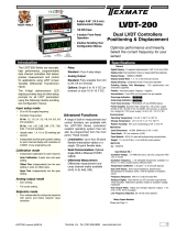
Figure 2 – IST3/IST4 Smar t Setup Registers Operational Flow Diagram
Smart Setup Registers
The Tiger controller uses three smart setup registers to configure all smar t input modules. Line frequency rejec-
tion (50 / 60 Hz) and ther mocouple type are configured in smart register 1 (SMT1). See Figure 2.
Thermocouple signals, TC1, TC2, TC3, and TC4, are then individually softw are selected for the four input
channels. Either signal can be selected f or CH1 via Code 2, CH2 via Code 4, CH3 via Code 5, and CH4
via Code 6.
Note: Once selected, the thermocouple type is the same f or all four channels.
Note: The same thermocouple signal can be selected f or two or more channels.
CH1
TC1
TC2
Input Signal 2 (TC2)
Input Signal 3 (TC3)
Input Signal 4 (TC4)
TC3
TC4
Tiger
Interface
g
Interface
g
I
2
C
Bu
s
Quad In
p
u
t
Analo
g
t
o
Digital
Convertor
16-bit
Resolution
TC4
TC3
TC2
TC1
Mi
c
r
o-
co
ntr
o
ll
er
Referenc
e
J
unctio
n
S
enso
r
PIN 1
PIN 2
PIN 3
PIN 4
PIN 5
PIN 6
PIN 7
PIN 8
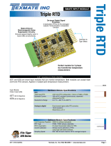
Reference
j
unction senso
r
thermall
y
bonded to th
e
co
nn
ec
t
o
r
b
l
oc
k.
Figure 3 – IST3/IST4 Quad Thermocouple Functional Schematic Diagram
J Type: (TC+) Iron
(TC–) Copper-nickel.
Commonly used in the
plastic moulding industry.
Good in dry and reducing
atmospheres.
K Type: (TC+)Nickel-chromium
(TC–) Nickel-aluminum.
Most commonly used
thermocouple with wide
temperature range. Good
in oxidizing atmospheres.

IST3-4 Data Sheet (NZ362) Page 3Texmate, Inc. Tel. (760) 598-9899 • www.texmate.com
Standard Setup Quick Start Guide
This section describes the procedures to enter the controller’s code structure and configure the input mod-
ule for the following standard settings:
•60 Hz Line Frequency (suitable for areas operating on 60 Hz power supplies).
•J Type Thermocouple.
•Thermocouple TC1 selected for channel 1 (CH1).
All other configuration settings are descr ibed in the following pages.
Prog.
SP1 SP2 SP4SP3 SP5 SP6
TEXMATE
Prog.
SP1 SP2 SP4SP3 SP5 SP6
TEXMATE
Prog.
SP1 SP2 SP4SP3 SP5 SP6
TEXMATE
Prog.
SP1 SP2 SP4SP3 SP5 SP6
TEXMATE
Prog.
SP1 SP2 SP4SP3 SP5 SP6
TEXMATE
Prog.
SP1 SP2 SP4SP3 SP5 SP6
TEXMATE
Prog.
SP1 SP2 SP4SP3 SP5 SP6
TEXMATE
Prog.
SP1 SP2 SP4SP3 SP5 SP6
TEXMATE
Prog.
SP1 SP2 SP4SP3 SP5 SP6
TEXMATE
Prog.
SP1 SP2 SP4SP3 SP5 SP6
TEXMATE
Prog.
SP1 SP2 SP4SP3 SP5 SP6
TEXMATE
Prog.
SP1 SP2 SP4SP3 SP5 SP6
TEXMATE
Prog.
SP1 SP2 SP4SP3 SP5 SP6
TEXMATE
X
Prog.
SP1 SP2 SP4SP3 SP5 SP6
TEXMATE
Prog.
SP1 SP2 SP4SP3 SP5 SP6
TEXMATE
To
Step
6
OR
From Step 5
OR
Press
3
Press
1
Press
1
Press
1
Press
at same
time
Press
at same
time
Press
at same
time
Press
at same
time
Step 1
Step 2
Step 3
Step 4
Step 5
Step 6
Step 7
Step 8
Step 9
Enter the Brightness
Mode
Pass the Brightness
Mode and enter
Code 2
Operational Display
Operational Display
Exit Code 2 and return
to the operational
display
Enter the Smart
Register 1 (SMt1)
Setup Mode
Return to Code 2
and select the
thermocouple for CH1
Save settings and
return to Code 2
Example
OR
Set Code 2 to [X77]:
1st Digit = 1 not relevant
2nd Digit = 7 Selects Smart Input Module
3rd Digit = 7 Selects Smart Input Module
Register 1 Code Setup
Set SMt1 to [100]:
1st Digit = 1 Selects 60 Hz noise rejection
2nd Digit = 0 Not relevant
3rd Digit = 0 Selects J type thermocouple
X
Set Code 2 to [X70]:
1st Digit = X not relevant
2nd Digit = 7 Selects Smart Input Module
3rd Digit = 0 Selects Average TC1 (10 Hz)
from the output register map
Example
X
X
Programming Tip
The f ollowing procedure uses a DI-50 displa y.
The readings sho wn may differ for other displa y
versions.

Texmate, Inc. Tel. (760) 598-9899 • www.texmate.comPage 4 IST3-4 Data Sheet (NZ362)
Programming Procedures
The f ollowing prog ramming procedures co ver all the steps required to configure smar t input module
IST3/IST4. Steps 1to 5describe how to select the line frequency and the thermocouple type through
smart register 1 (SMT1).
Steps 7to 12 describe how to select a specific ther mocouple from the output registers f or channels 1, 2,
3, or 4 as required.
2
1
MEASUREMENT TASK
0 Voltage, Current
1 TC (3rd digit selects type of TC)
2 RTD 3-wire (3rd digit selects type
of RTD)
3 RTD 2- or 4-wire (3rd digit selects
type of RTD)
4 Frequency
5Period
6 Counter
7 Smart Input Module
SECOND DIGITFIRST DIGIT
This setting enters the smart register 1 code
setup menu.
Press the and buttons at the same time to enter the main programming mode.
P
Press the button three times to enter Code 2. Set Code 2 to [X77].
P
OUTPUT REGISTER MAP
0 Averaged TC1 (10 Hz)
1 Averaged TC2 (10 Hz)
2 Averaged TC3 (10 Hz)
3 Averaged TC4 (10 Hz)
4-
5-
6-
7 Smart input module register 1
code setup
THIRD DIGIT
0 10 Hz
1 10 Hz
2 100 Hz
3 100 Hz
TIGER PROCESSING RATE
Note: The output registers in the 3rd digit
are specific to the Quad Thermocouple
input module. These registers vary for each
different smart input module.
3
NOT USED
0-
1-
2-
3-
4-
5-
6-
7-
SECOND DIGIT
THERMOCOUPLE TYPE
0 J type
1 K type
2-
3-
4-
5-
6-
7-
THIRD DIGIT
FIRST DIGIT
0 -
1 60 Hz rejection
2 -
3 50 Hz rejection
This menu provides settings unique to smart
register 1 of input module IST3/4.
Press the button.
P
Using the buttons,
select either 50 or 60 Hz line frequency rejection in the
1st digit and the thermocouple type in the 3rd digit.
2nd digit settings are not relevant and should be left at z ero (0).
4
FREQUENCY SELECT
5Press the button. The display returns to [Cod_2] [X77].
P
6Using the button, reset the 3rd digit to z ero [X70] to leave the smart register 1 menu.
Note: Leaving the 3rd digit as 7 means the display constantly cycles between [Cod_2] and [SMt1].
Press the and buttons at the same time again to re-enter the main prog ramming mode,
then press the button three times to enter Code 2.
P
P
8
Select a Channel
Press the and buttons at the same time to retur n to the operational display.
P
7
Note: 10 Hz is the aver-
age output for all four
thermocouple inputs.
J Type Thermocouple
K Type Thermocouple
0 °C to 700 °C
0 °C to 1100 °C
Operational Temperature Range Approximate continuous w orking temperature range of measur ing
junction. Not related to wire diameters and conducted insulation.
Refer IEC 584.2, 1982 (BS EN 60584.2, 1993) Inter nal Standards
for Thermocouple Characteristics.
Select a thermocouple output from the output register map of the required c hannel
Channel 1

IST3-4 Data Sheet (NZ362) Page 5Texmate, Inc. Tel. (760) 598-9899 • www.texmate.com
*Note:
The logic f or CH2 is not the same as CH1,
CH3, or CH4. The 1st and 3rd digits must both
be set to 0.Selecting 040 to 070 in the 2nd digit
of Code 4 directly selects one of the f ollowing
settings in the output register map (3rd digit):
CH1
Set Code 2 to [X7X]. Select the required processing rate for CH1 in the 1st digit and the required
register map settings in the 3rd digit.
2nd digit settings are not relevant and should be left at z ero (0).
9
Note: The output register
map is different for each
smart input module type.
OUTPUT REGISTER MAP
0 Averaged TC1 (10 Hz)
1 Averaged TC2 (10 Hz)
2 Averaged TC3 (10 Hz)
3 Averaged TC4 (10 Hz)
4-
5-
6-
7 Smart input module register 1
code setup
THIRD DIGIT
CH2
Set Code 4 to [0X0]. Select the required register map settings f or CH2 in the 2nd digit.
10
MEASUREMENT TASK
0 Voltage, Current
1-
2-
3-
FOR VOLTAGE & CURRENT
0 Channel 2 Disabled
1 Direct (no post processing)
2 Square Root of Channel 2
3 Inverse of Channel 2
4 Output Register 1 (smart module)*
5 Output Register 2 (smart module)*
6 Output Register 3 (smart module)*
7 Output Register 4 (smart module)*
SECOND DIGITFIRST DIGIT
4 selects
5 selects
6 selects
7 selects
2nd Digit Output Register Map
0 Averaged TC1 (10 Hz)
1 Averaged TC2 (10 Hz)
2 Averaged TC3 (10 Hz)
3 Averaged TC4 (10 Hz)
FIRST DIGIT
0 10 Hz
1 10 Hz
2 100 Hz
3 100 Hz
TIGER PROCESSING RATE
Press the and buttons at the same
time to return to the operational display.
P
Press the button to save the settings.
P
CH3
CH4
Enter Code 5 and select the required register map settings f or CH3 in the 3rd digit.
Enter Code 6 and select the required register map settings f or CH4 in the 3rd digit.
11
11
12
FIRST DIGIT
0 Direct Display of Input (no processing)
1 Square Root of Channel 4
2 Inverse of Channel 4
3Meters with 4 kB memor y
NO Linearization
Meters with 32 kB memor y
32-point Linear ization of CH4 using
Ta bl e 4
Note:
All linear ization tab les are set up in
the Calibration Mode [24X].
CH4 POST PROCESSING
Note: The output register
map is different for each
smart input module type.
OUTPUT REGISTER MAP
0 Averaged TC1 (10 Hz)
1 Averaged TC2 (10 Hz)
2 Averaged TC3 (10 Hz)
3 Averaged TC4 (10 Hz)
4-
5-
6-
7 Smart input module register 1
code setup
THIRD DIGIT
FIRST DIGIT
0 Direct Display of Input (no processing)
1 Square Root of Channel 3
2 Inverse of Channel 3
3Meters with 4 kB memor y
NO Linearization
Meters with 32 kB memor y
32-point Linear ization of CH3 using
Ta bl e 3
Note:
All linear ization tab les are set up in
the Calibration Mode [24X].
CH3 POST PROCESSING
Channel 2
Channel 3
Channel 4

Texmate, Inc. Tel. (760) 598-9899 • www.texmate.comPage 6 IST3-4 Data Sheet (NZ362)
Calibration
As the calibration procedure requires a calibr ation source that can output stab le µV signals, calibration of
the four channels is normally done in the factory prior to shipping.
PIN 1
K Type
Thermocouple
Plug
PIN 2
TC1+
TC1–
–+
K Type
Thermocouple
Wire
IST3/IST4
Terminal Block
TC
Thermocouple
Calibration
Source
PIN 3
PIN 4
PIN 5
PIN 6
PIN 7
PIN 8
TC2+
TC2–
TC3+
TC3–
TC4+
TC4–
Calibrating 4 Channels for K Type Thermocouple
If user calibration is required, the f ollowing procedure should be f ollowed. It is assumed that the user has
a thermocouple calibration source available. When the controller is switched on, allow a few minutes warm-
up time to let the reference junction stabilize to the connector ter minal block temperature.
Connect a standard K type ther mocouple plug to the calibration source.
a) Set the calibration source to 0 °C.
b) Enter [CAL] [111] and set to [ZEro] setting.
Connect the standard K type ther mocouple cable to the rele vant pins on the input module of the
thermocouple input to be calibrated.
2Connect to the Calibrated Source
3Connect to the Input Module
4Set the Low Setting
a) Set the calibration source to 100 °C.
b) Set to [SPAn] setting to 100.0.
5Set the High Setting
6Repeat Steps
Repeat Steps 2 to 4 for all required thermocouples and channels.
See 2-point Calibration Mode Example on Page 7 for a step-by-step calibration procedure.
Note:
One thermocouple can be assigned to one or more c hannels (e.g. TC1 assigned to
CH1 to CH4), but each channel can accept only one thermocouple input.
See Page 4 and carry out Steps 1 to 7 to select the required line frequency and thermocouple type.
1Setup Smart Register 1 (SMT1)

IST3-4 Data Sheet (NZ362) Page 7Texmate, Inc. Tel. (760) 598-9899 • www.texmate.com
Prog.
SP1 SP2 SP4SP3 SP5 SP6
TEXMATE
Prog.
SP1 SP2 SP4SP3 SP5 SP6
TEXMATE
Prog.
SP1 SP2 SP4SP3 SP5 SP6
TEXMATE
Prog.
SP1 SP2 SP4SP3 SP5 SP6
TEXMATE
Prog.
SP1 SP2 SP4SP3 SP5 SP6
TEXMATE
Prog.
SP1 SP2 SP4SP3 SP5 SP6
TEXMATE
Prog.
SP1 SP2 SP4SP3 SP5 SP6
TEXMATE
Prog.
SP1 SP2 SP4SP3 SP5 SP6
TEXMATE
Prog.
SP1 SP2 SP4SP3 SP5 SP6
TEXMATE
Prog.
SP1 SP2 SP4SP3 SP5 SP6
TEXMATE
Prog.
SP1 SP2 SP4SP3 SP5 SP6
TEXMATE
Prog.
SP1 SP2 SP4SP3 SP5 SP6
TEXMATE
Prog.
SP1 SP2 SP4SP3 SP5 SP6
TEXMATE
Prog.
SP1 SP2 SP4SP3 SP5 SP6
TEXMATE
Prog.
SP1 SP2 SP4SP3 SP5 SP6
TEXMATE
X
Prog.
SP1 SP2 SP4SP3 SP5 SP6
TEXMATE
Prog.
SP1 SP2 SP4SP3 SP5 SP6
TEXMATE
To Step 7
OR
From Step 6
5.2. Apply the LOW
input signal
OR
OR
Press
1
Press
1
Press
1
Press
1
Press
at same
time
Press
at same
time
Press
at same
time
Press
at same
time
Step 1
Step 2
Step 3
Step 4
Step 5
Step 6
7.2. Apply the HIGH
input signal
Step 7
Step 8
Step 9
Step 10
Step 11
Enter the
brightness
mode
Pass the brightness
mode and the enter
calibration mode
Select the no function
calibration mode [000]
Save calibration mode
[000] setting and enter
Code 1
Operational Display
Operational Display
Exit Code 1 and return
to the operational display
Enter calibration
mode [111] for 2-point
calibration of CH1
5.1. Adjust display to
desired reading for
zero input
7.1. Adjust display to
desired reading for
span input
Set reading for zero
load into meter and
enter span mode
Save zero and span
settings and re-enter
calibration mode
Example
Example
OR
LOW
Signal
HIGH
Signal
Set calibration mode to [111]:
1st Digit = 1
Selects calibration procedures
2nd Digit = 1
Selects 2-point calibration
3rd Digit = 1
Selects CH1 for calibration
Prog.
SP1 SP2 SP4SP3 SP5 SP6
TEXMATE
Press
1
[111] for CH1
[112] for CH2
[113] for CH3
[114] for CH4
2-point Calibration
Mode Example
ST
STAR
ART HERE
T HERE

Texmate, Inc. Tel. (760) 598-9899 • www.texmate.comPage 8 IST3-4 Data Sheet (NZ362)
Customer Configuration Settings:
1st Digit 2nd Digit 3rd Digit
1st Digit 2nd Digit 3rd Digit
CH3
CH4
CH2
1st Digit 2nd Digit 3rd Digit
1st Digit 2nd Digit 3rd Digit
1st Digit 2nd Digit 3rd Digit
CH1
7
7
00
WARRANTY
Texmate warrants that its products are free from def ects in mater ial and w orkmanship under
normal use and ser vice for a period of one y ear from date of shipment. Texmate’s obligations
under this warranty are limited to replacement or repair, at its option, at its factory, of any of the
products which shall, within the applicable period after shipment, be returned to Texmate’s facil-
ity, tr ansportation charges pre-paid, and which are , after e xamination, disclosed to the satis-
faction of Texmate to be thus def ective. The warranty shall not apply to an y equipment which
shall have been repaired or altered, except by Texmate, or which shall have been subjected to
misuse, negligence , or accident. In no case shall Texmate’s liability e xceed the or iginal pur-
chase price. The aforementioned provisions do not e xtend the or iginal warranty period of an y
product which has been either repaired or replaced b y Texmate.
USER’S RESPONSIBILITY
We are pleased to offer suggestions on the use of our v arious products either by way of print-
ed matter or through direct contact with our sales/application engineering staff. However, since
we ha ve no control o ver the use of our products once the y are shipped, NO WARRANTY
WHETHER OF MERCHANT ABILITY, FITNESS FOR PURPOSE, OR O THERWISE is made
beyond the repair, replacement, or refund of purchase pr ice at the sole discretion of Texmate.
Users shall deter mine the suitability of the product f or the intended application bef ore using,
and the users assume all risk and liability whatsoever in connection therewith, regardless of any
of our suggestions or statements as to application or constr uction. In no event shall Texmate’s
liability, in law or otherwise, be in excess of the purchase pr ice of the product.
Texmate cannot assume responsibility for any circuitry described. No circuit patent or software
licenses are implied. Texmate reserves the right to change circuitry, operating software, speci-
fications, and prices without notice at any time.
For product details visit www.texmate.com
Tel: 1-760-598-9899 • USA 1-800-839-6283 • That’s 1-800-TEXMATE
Email: [email protected] • Web: www.texmate.com
1934 Kellogg Ave. • Carlsbad, CA 92008
/