Page is loading ...


2
EN
Contents Smart Touch Cabin Control
Contents
Service Center & Dealer Locations
Visit: www.dometic.com
Read these instructions carefully. These instructions
MUST stay with this product.
1 Explanation of Symbols and Safety
Instructions ............................ 2
1.1 Recognize Safety Information .............3
1.2 Understand Signal Words ................3
1.3 Supplemental Directives .................3
1.4 General Safety Messages ................3
2 Intended Use ........................... 3
3 General Information ..................... 4
3.1 How it Works ..........................4
3.2 Tools and Materials .....................4
3.3 Understanding the Menu Screen Layout ....5
3.4 Understanding the Settings Screen Layout ..5
3.5 Understanding the Home Screen ..........6
3.6 Understanding the Main Screen ...........6
4 Specifications .......................... 7
5 Wiring Diagrams ........................ 8
5.1 Understanding the DX Wiring Diagram .....8
5.2 Understanding the CW Wiring Diagram ....9
6 Installation and Setup ................... 10
6.1 Choosing the Location .................10
6.2 Installing the Display Panel ..............10
6.3 Installing the Optional Sensor Hardware ... 11
7 Commissioning the System .............. 12
8 Operation ............................. 14
8.1 Understanding the Operating Cycles .....14
8.2 Understanding the Operating Modes .....15
8.3 Understanding the Fan Modes ...........16
9 Control Parameters .................... 17
9.1 Understanding the General Settings ......17
9.2 Understanding the DX Operational
Settings .............................21
9.3 Understanding the CW Operational
Settings .............................25
9.4 Understanding the Memory Settings ......25
9.5 Understanding the Program Scheduler ....26
9.6 Understanding the Date/Time Menu ......27
9.7 Understanding the System Menu ........27
9.8 Understanding the Troubleshooting/
Commissioning Screens ................30
9.9 Understanding the Fault Handling,
History & Run Hours ...................31
9.10 Navigation Trees ......................33
10 Maintenance .......................... 36
10.1 Checking the Return-Air Filter ............36
10.2 Energizing the Reversing Valve Units –
DX Only .............................36
10.3 Checking the Seawater Strainer – DX Only .36
10.4 Cleaning the Condenser Coil – DX Only ...36
10.5 Winterizing the System – DX Only ........37
11 Troubleshooting ....................... 37
12 Disposal ..............................43
13 Warranty Information ................... 43
1 Explanation of Symbols and
Safety Instructions
This manual has safety information and instructions to
help you eliminate or reduce the risk of accidents and
injuries.

3
EN
Smart Touch Cabin Control Intended Use
1.1 Recognize Safety Information
This is the safety alert symbol. It is used to alert
you to potential physical injury hazards. Obey all
safety messages that follow this symbol to avoid
possible injury or death.
1.2 Understand Signal Words
A signal word will identify safety messages and property
damage messages, and also will indicate the degree or
level of hazard seriousness.
DANGER!
Indicates a hazardous situation that, if not avoided,
will result in death or serious injury.
WARNING
Indicates a hazardous situation that, if not avoided,
could result in death or serious injury.
CAUTION
Indicates a hazardous situation that, if not avoided,
could result in minor or moderate injury.
NOTICE: Used to address practices not related to
physical injury.
I
Indicates additional information that is not related
to physical injury.
1.3 Supplemental Directives
To reduce the risk of accidents and injuries, please
observe the following directives before proceeding to
install or operate this appliance:
• Read and follow all safety information and
instructions.
• Read and understand these instructions before
installing or operating this product.
• The installation must comply with all applicable local
or national codes, including the latest edition of the
following standards:
– American Boat and Yacht Council (ABYC)
– ANSI/NFPA70, National Electrical Code (NEC)
1.4 General Safety Messages
WARNING: ELECTRICAL SHOCK, FIRE, AND/
OR EXPLOSION HAZARD. Failure to obey the
following warnings could result in death or
serious injury:
• Use only Dometic replacement parts and
components that are specifically approved for use
with the appliance.
• Avoid improper installation, adjustment, alterations,
service, or maintenance of the appliance. Service and
maintenance must be done by a qualified service
person only.
• Do not modify this product in any way. Modification
can be extremely hazardous.
• Use care when diagnosing and/or adjusting
components on a powered unit.
NOTICE: Do not operate the air conditioning unit in
water that is cooler than 38 °F (3 °C). Failure to obey this
notice could lead to water freezing in the condenser coil
which can damage to the unit.
2 Intended Use
The Dometic Smart Touch Cabin Control is a
microcontroller-based unit designed for use with direct
expansion (DX), reverse-cycle air conditioning systems.
The Smart Touch Cabin Control offers 22 programmable
parameters for custom installations, including a
dehumidification mode to control relative humidity and
de-icing to prevent evaporator coil icing. The system
offers a nonvolatile memory that retains settings without
batteries and CAN-bus network capability. Optional
sensors are available for further customization.
Dometic Corporation reserves the right to modify
appearances and specifications without notice.
The manufacturer accepts no liability for damage in the
following cases:
• Faulty assembly or connection
• Damage to the product resulting from mechanical
influences and excess voltage

4
EN
General Information Smart Touch Cabin Control
• Alterations to the product without express permission
from the manufacturer
• Use for purposes other than those described in the
operating manual
3 General Information
This section provides information on the features, tools,
and high-level screen displays.
This manual provides all the necessary information for
proper installation and operation of the Smart Touch
Cabin Control. Poor installation and misunderstood
operating parameters will result in unsatisfactory
performance and possible failure.
I
The images used in this document are for reference
purposes only. Components and component
locations may vary according to specific product
models. Measurements may vary ±0.38 in. (10 mm).
3.1 How it Works
This section describes the affects of seawater on a
marine climate control system.
The basic principle of an air conditioning unit is the
movement of heat. To cool, heat is removed from the
inside cabin air and transferred to the seawater. To warm,
heat is extracted from the seawater and discharged into
the living space. The efficiency of the system operation
depends on both seawater and cabin temperatures.
• Cool mode operation. The air conditioning unit
operates most efficiently in seawater temperatures
below 90°F (32°C). At higher seawater
temperatures, the unit will operate at a reduced
capacity. A high-pressure shutdown may occur at
higher seawater temperatures.
• Heat mode operation. As the seawater gets
colder, less heat is available and the heating efficiency
is reduced. Full heating capacity is obtained at
approximately 55°F (13°C) seawater temperature.
Performance drops to about 50% of the rated
capacity in 40°F (4°C) water.
In water temperatures below 40°F (4°C), the system
pressure can be so low that the unit will shut down
on a low-pressure fault. This problem is compounded
when the cabin is also cold. See “Troubleshooting” on
page37 for more information.
3.2 Tools and Materials
Dometic recommends that the following tools and
materials be used while installing the appliance:
Recommended Tools
Phillips-head Screwdriver Saw
Safety Glasses Thermal Mastic
Multimeter
Included Parts Quantity
Smart Touch Cabin Control 1
Screws 4
Additional Parts DX CW
Required for CW installations (not included)
Water Inlet Temperature Sensor X
Optional Parts
Outside Air Temperature (OAT) Sensor X X
Inside Air Temperature Sensor X X
Room Temperature/Relative Humidity
Combination Sensor
X X
Seawater Low-Limit Temperature Sensor X
Pump Sentry Water Sensor X
I
The maximum length for display and sensor cable is
75 (22.9 m). Optional items are not included with
the standard control package.

5
EN
Smart Touch Cabin Control General Information
3.3 Understanding the Menu
Screen Layout
This screen is an example of a typical menu screen and
navigation buttons. Actual menu screens may vary in
appearance.
q r
w r
e r
1 Menu Screen Layout
No. Button Description
q
Home Returns to the home screen
w
Back Returns to the last screen or menu
e
Scroll Down Moves to the next page of settings
options
r
Main Menu
Options
Selects the menu option to modify
3.4 Understanding the Settings
Screen Layout
This screen is an example of a typical setting screen.
Actual settings screens may vary in appearance.
q
w
t
e
r
y
2 Settings Screen Layout
No. Button Description
q
Home Returns to the home screen
w
Back Returns to the last screen or menu
e
Save Saves the displayed value
r
Value Display Displays the current value of the item or
parameter
t
Up Increases the set point by one degree with
each press and release operation
y
Down Decreases the set point by one degree
with each press and release operation

6
EN
General Information Smart Touch Cabin Control
3.5 Understanding the Home
Screen
This starting screen displays when the Smart Touch
Cabin Control is turned on.
w
r
e
u
t
y
q
3 Main Screen Icon Functions
No. Button Description
q
Force Sleep Forces the sleep mode to initiate
immediately, if sleep delay is on/enabled
with a press and release
w
Temperature Cycles through available set point(s)
(inside, outside, service, water, and
humidity temperatures) with a press and
release
e
Main Screen Displays the main screen with a press and
release
r
Status Indicates the system status (off, pending,
active, standby, or fault)
t
Up Displays the set point with a press and
release. Press and release the up icon as
many times as desired to increase the set
point. The set point increases one degree
with each press and release.
y
Down Displays the set point with a press and
release. Press and release the down icon
as many times as desired to decrease the
set point. The set point decreases one
degree with each press and release.
u
Power Toggle between On and Off with a press
and release
3.6 Understanding the Main
Screen
Enter from the home screen to access the most basic
functions as well as the menu for more options.
e
q
w
tr
y
u
i
o
a
s
4 Main Screen Icon Functions
No. Button Description
q
Mode Changes the currently active mode
with a press and release
Auto Switches to cool or heat to satisfy
the temperature set point
Cool Indicates the system is in cooling
mode or when the unit is in an
automatic mode cooling cycle
Heat Indicates the system is in heating
mode or when the unit is in an
automatic mode heating cycle
Auxiliary Heat Indicates aux heat-only mode or
when the unit is in an automatic
mode auxiliary heating cycle
Dehumidification Controls humidity when the vessel is
unoccupied
w
Fan Mode Cycles through low, medium, high,
and auto fan speeds with a press
and release
e
Main Menu Displays the main menu with a press
and release
r
Fan Speed and
Mode Indicator
Above the line, indicates if the
fan speed is automatic or manual.
Displays the current speed below
the line.
t
Sensor Indicator Specifies which temperature is
displayed (inside, outside, service,
or water temperature) based on the
sensors installed.

7
EN
Smart Touch Cabin Control Specifications
No. Button Description
y
Temperature
Indicator
Displays the temperature based on the
sensor indicator.
u
Status Shows if a fault has occurred
i
Schedule Shows a schedule program is active and
the specific times and days
o
Up Increases the set point one degree with a
press and release
a
Down Decreases the set point one degree with
a press and release
s
Power Toggles between On and Off mode
4 Specifications
This section describes the display, sensor, cabling,
environmental, and electrical specifications for the unit.
Installation Specifications
Display Dimensions
Display Panel 4.3 x 2.9 in. (110 x 73 mm)
Panel Cut Out 2.9 x 2.2 in. (74 x 55 mm)
Cable Lengths
Display Cable Self-Contained 15 (4.6 m) Standard
Inside Air Temperature Sensor
(optional)
7 (2.1 m) Standard
OAT Sensor (optional) 15 (4.6 m) Standard
All custom cable lengths supplied in
standard 5.0 (1.5 m) increments
75 (22.9 m) Maximum
Sensor Inputs
High Refrigerant Pressure 1
Low Refrigerant Pressure (optional) 1
Inside Air Temperature Sensor
(optional)
1
OAT Sensor (optional) 1
Pump Sentry Water Sensor (optional) 1
Room Temperature/Relative Humidity
Combination Sensor (optional)
1
Water Inlet Temperature Sensor
(CW Installations Only)
1
Operational Specifications
Environmental
Set Point Operating Range 65–85°F
(18–29°C)
Ambient Temperature
Operating Range Displayed
5–150°F
(-15–66°C)
Sensor Accuracy ±2°F @ 77°F
(±1°C @ 25°C)
Minimum Operating
Temperature
0°F (-18°C)
Maximum Ambient Operating
Temperature
180°F (82°C)
Electrical
Low Voltage Limit 110–120 Volt
Units
95 VAC
Low Voltage Limit 208–240
Volt Units
195 VAC
Low Voltage Processor Reset 50 VAC
Universal Line Voltage 100–240 VAC
Frequency 50 or 60 Hz
Fan Output 6 A @ 115 VAC
6 A @ 230 VAC
Valve Output 1/4 A @ 115/230 VAC
Heater Output
1
(using valve relay)
15 A @ 115 VAC
10 A @ 230 VAC
Aux Heater Output
(using off-board relay)
30 A @ 115 VAC /
230 VAC
Pump Output 1/4 HP @ 115 VAC
1/2 HP @ 230 VAC
Compressor Output 1 HP @ 115 VAC
2 HP @ 230 VAC
Maximum Rh Conditions 99% Non Condensing
Power Consumption < 5 W
1
Only applies to soware revision A26 and older.

8
EN
Wiring Diagrams Smart Touch Cabin Control
5 Wiring Diagrams
The following diagrams show the component
connections for the direct expansion (DX) and chilled
water (CW) systems.
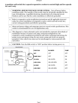
5.1 Understanding the DX Wiring
Diagram
WARNING: ELECTRICAL SHOCK.
Turn the power off before opening the electrical
box. Failure to do so could result in death or serious
injury.
Run Capacitor
Low-Pressure
Switch
High-Pressure
Switch
Optional
DC Blower
Comp L1
Pump L1
Pump L2
0-10 VDC
GND
Fan L1
Comp L2
Compressor
Inside Air Sensor Jack
Not Active
Optional Water-Out Temperature Sensor
Ground
Start
Capacitor
Start Relay
1
6
4
5
2
L2
AC
Fan
Fan Run
Capacitor
L1
L1
L2
Pump or
Pump Relay Panel
JP5 Temperature Sensor Selection Jumper
JP2 Low Pressure Switch Jumper
Reversing Valve or
Electric Heat
Gate Terminals to Aux Heat Relay
Display Jacks (for 8- or 6-pin Display and Cables)
Optional Outside Air Temperature Sensor
5 Wiring Diagram - DX

9
EN
Smart Touch Cabin Control Wiring Diagrams
5.2 Understanding the CW Wiring
Diagram
JP1 System Selection Jumper
Inside Air Temperature Sensor Jack
Required Water-In Temperature Sensor
Optional Water-Out Temperature Sensor
Optional Outside Air Temperature Sensor
JP5 Temperature Sensor Selection
Jumper
Ground
Fan
Water Valve
Electric Heat Strip
Fan Run
Capacitor
L2
L2
L2
AC
L2
L1
L1
L1
L1
Display Jacks (for 8- or 6-pin Display and Cables)
Optional DC Blower
GND
For Humidistat For Changeover Switch
COM COM
0-10 VDC
SMX DISPLAYS ONLY
6 Wiring Diagram CW

10
EN
Installation and Setup Smart Touch Cabin Control
6 Installation and Setup
NOTICE: Do not use a screw gun and do not over-
tighten the screws when mounting the display because
either method may damage the display.
NOTICE: The system’s built-in air sensor is located in
the control display panel; therefore, you must locate
the display on an interior wall at eye level. Do not
locate in direct sunlight or inside a cabinet. If these
conditions cannot be met, you must purchase the
optional inside air temperature sensor and install it in the
return-air stream.
NOTICE: Do not staple sensor cables when mounting.
This section describes how to install and set up the Smart
Touch Cabin Control.
6.1 Choosing the Location
This section describes the location requirements.
q
7 Front Panel Temperature Sensor
q
Temperature Sensor Location
1. Before mounting the control panel, consider the
location. The display panel’s built-in air sensor
provides excellent room-air temperature sensing
when properly located and installed. For the sensor
location on the display panel, see Figure 7.
I
If you cannot mount the display
in a suitable location, install the
optional inside air temperature sensor.
2. Ensure the following requirements are met when
mounting the display panel.
– Install the display on an inside wall, slightly higher
than mid-height of the cabin.
– Select a location with freely circulating air where
the temperature sensor can best sense average
temperature.
– Select a location within 15 (4.5 m) of the air
conditioning unit to accommodate the length of
the display cable (custom lengths are available).
– Avoid installing the display in direct sunlight, near
any heat-producing appliances, or in a bulkhead
where temperatures radiating from behind the
panel may affect performance.
– Avoid installing the display in the supply air
stream, above or below a supply air or return-air
grille, behind a door, in a corner, under a stairwell,
or any place where there is no freely circulating air.
6.2 Installing the Display Panel
This section describes how to mount the display panel.
w
q
8 Top View Mounting Dimensions
q
1 in. (25 mm)
w
0.4 in. (10 mm)

11
EN
Smart Touch Cabin Control Installation and Setup
w
e
q
9 Cut Out Dimensions (Drawing not to scale – not a template)
q
2.9 in. (74 mm)
e
3.5 in. (88 mm)
w
2.2 in. (56 mm)
1. Make the cut-out for the display panel to measure
2.9 in. (74 mm) wide by 2.2 in. (56 mm) high.
2. Plug the 8-pin connector end of the display cable
into the upper-right socket on the circuit board in the
electric box.
3. Plug the other end to the back of the display panel.
4. Secure the display panel to the bulkhead using the
four screws provided.
5. When the display is securely mounted, place the
bezel over the display frame and snap into place.
6.3 Installing the Optional Sensor
Hardware
This section describes where and how to mount
additional sensors.
6.3.1 Inside Air Temperature
If the display cannot be mounted in a proper location,
install this optional sensor to monitor the cabin
temperature. The installed sensor will override the
display built-in temperature sensor.
I
The sensor’s distance from the air conditioner must
be within the 7 (2.1 m) standard cable length.
1. Mount the sensor in the return-air stream behind the
opening of the return-air grille.
2. Plug the 6-pin connector cable into the inside jack
#J3 in the upper-le corner of the circuit board.
6.3.2 Outside Air Temperature
Install this optional sensor to monitor the outside air
temperature.
I
The sensor’s cables are available in various lengths.
1. Mount the sensor outside, but not in direct sunlight.
2. Plug the cable into the OAT plug #P6.
6.3.3 Room Temperature/Relative
Humidity Combination
Install this optional sensor to monitor the relative
humidity of the cabin.
I
The control board automatically detects the this
sensor and immediately starts measuring humidity.
1. Mount the sensor in the same location as the
optional inside air temperature sensor.
2. Plug the sensor’s 6-pin connector into the inside
temperature socket at the edge of the circuit board.
6.3.4 Pump Sentry Water – DX Only
Install this optional DX sensor to monitor the condenser
coil temperature.
I
This sensor must be enabled with the Pump Sentry
feature. See section “Understanding the DX
Operational Settings” on page21.
1. Mount the sensor at the condenser coil outlet and
install insulation around it.
2. Plug the sensor into the H2O OUT plug #P5.

12
EN
Commissioning the System Smart Touch Cabin Control
6.3.5 Seawater Low-Limit Temperature –
DX Only
Install this optional DX sensor to monitor the temperature
of the seawater feeding the air conditioning unit.
1. Mount the sensor in direct contact with the copper
pipe, using thermal mastic to ensure a good heat
transfer.
2. Strap the sensor wire in place for strain relief and to
prevent the sensor from being accidentally removed.
3. Plug the sensor’s 2-pin connector into the loop water
out (blue) socket located on the circuit board.
6.3.6 Water Inlet Temperature – CW Only
Install this optional CW sensor to monitor the water
temperature.
When using the AH Mode with a CW air handler:
1. Ensure the sensor has good contact with the copper
pipe.
2. Attach the sensor to the chilled-water inlet on the air
handler.
3. Plug the water inlet sensor cable into the H2O IN
plug #P4.
I
Do not attach to a rubber hose.
7 Commissioning the System
NOTICE: Do not turn the unit off and then immediately
turn it back on. Allow at least 30 seconds for the
refrigerant pressure to equalize.
This section describes the commissioning procedure
and provides a commissioning checklist.
7.3.1 Commissioning Procedure
This section outlines the commissioning procedure
to test the main inputs and outputs of a new system.
The procedure also offers guidance when selecting
important system settings.
I
The commissioning procedure varies depending
on the CW or DX system.
To begin the commissioning procedure:
1. Ensure the seawater-intake ball valve/seacock is
open.
2. Make sure the control is powered Off.
3. Turn on the air conditioning unit circuit breaker and
the seawater pump circuit breaker, if installed.
4. Turn the control On.
5. Press the fan icon, and verify that the fan is running
and that there is steady airflow out of the supply air
grille.
6. Select a temperature set point lower than the current
cabin temperature to start the compressor and
seawater pump.
7. Check for a steady solid stream of water from the
overboard discharge.
8. Verify there is steady airflow from the supply air grille.
I
If the unit does not appear to be operating
properly, see section “Troubleshooting” on
page37.
To navigate through the commissioning procedure:
1. Press the home button to exit the procedure.
2. Press the return arrow to exit the procedure and
return to the menu.
3. Press the down arrow to continue with the next step.
7.3.2 Commissioning the System
The steps in the commissioning procedure vary
depending on whether the system is a chilled water
(CW) or a direct expansion (DX) air conditioning system.
These tables clarify the commissioning procedures for
the CW system, followed by the DX system.

13
EN
Smart Touch Cabin Control Commissioning the System
CW and DX - Commissioning Procedure
Screens 1 - 5
Screen Description
1
Introduction and System Configuration
The following system components were detected to
configure:
[Chilled water system with electric heater]
[Alternative air sensor is connected]
[Direct expansion system without electric heater]
To modify these settings exit the commissioning
procedure, adjust the program parameters, and run the
commissioning procedure again.
Press the down button to continue.
2
Inside Temperature Sensor
If using the display sensor, make sure the display is not
located in direct sunlight, near an outside door, or near
the supply air stream.
If using an alternative air sensor, make sure it is placed in
the return-air stream.
Press the down button to continue.
3
Low Fan Speed Test
The fan is now energized at the above mentioned
speed. Verify the supply air flow and the acoustics are
correct.
To modify these settings, exit the commissioning
procedure, adjust the program parameters, and run the
commissioning procedure again.
Press the down button to continue.
4
Medium Fan Speed Test
The fan is now energized at the above mentioned
speed. Please verify the supply air flow and the
acoustics are correct.
To modify these settings, exit the commissioning
procedure, adjust the program parameters, and run the
commissioning procedure again.
Press the down button to continue.
5
High Fan Speed Test
The fan is now energized at the above mentioned
speed. Please verify that the supply air flow and the
acoustics are correct.
To modify these settings, exit the commissioning
procedure, adjust the program parameters, and run the
commissioning procedure again.
Press the down button to continue.
CW only - Commissioning Procedure
Screens 6 - 10
Screen Description
6
Water Temperature Sensor
The water temperature reading is: 49 °F.
The difference between the water temperature and the
inside temperature must exceed the differential setting
to open the valve.
To modify these settings, exit the commissioning
procedure, adjust the program parameters, and run the
commissioning procedure again.
Press the down button to continue.
CW only - Commissioning Procedure
Screens 6 - 10
Screen Description
7
Water Valve Test
The water valve output test is now running and the valve
output is energized. Please verify that the valve is open
and that the supply air is cooler than the room ambient
temperature.
Press the down button to continue.
8 Electric Heater Test
The electric heater output test is now running and the
electric heater is energized. Please verify that the heater
is operating and that the supply air is warmer than the
room ambient temperature.
Press the down button to continue.
9 Auxiliary (Aux) Heater Test
The aux heater output test is now running and the aux
heater is energized. Please verify that the heater is
operating and that the supply air is warmer than the
room ambient temperature.
Press the down button to continue.
10 Pass Confirmation
Congratulations!
The commissioning procedure is now completed.
Press the down button to continue.
DX only - Commissioning Procedure
Screens 6 - 11
Screen Description
6
Fault Check
No faults are detected.
If the system has a low-pressure switch, verify that it is
wired and its enable jumper on the main board is cut.
Press the down button to continue.
7
Pump Test
The seawater pump test is now running and the pump
output is energized.
Please verify that the seawater pump is on and pumping
water overboard.
Press the down button to continue.
8 Cool Test
The cooling cycle test is now running and the
compressor should start within 15 seconds.
Please verify that the compressor is operating and
the supply air is cooler than the room ambient air
temperature.
Press the down button to continue.

14
EN
Operation Smart Touch Cabin Control
DX only - Commissioning Procedure
Screens 6 - 11
Screen Description
9 R/C Heat Test
The reverse-cycle heating test is now running and the
compressor should start within 15 seconds.
Please verify that the compressor is operating and the
supply air is warmer than the ambient air temperature.
Press the down button to continue.
10 Auxiliary (Aux) Heat Test
The aux heater output test is now running and the aux
heater is energized.
Please verify that the heater is operating and the supply
air is warmer than the ambient air temperature.
Press the down button to continue.
11 Pass Confirmation
Congratulations!
The commissioning procedure is now completed.
Press the down button to continue.
8 Operation
This section describes the operating features.
Use the main menu settings to adjust the operating
parameters and to fine-tune the system for the most
efficient operation. Variables such as ducting, sensor
location, and system layout affect the system operation.
The control has factory default settings stored in
permanent memory that can be recalled. To return to the
default settings, select main menu > control parameters
> recall defaults.
Reprogrammed, new settings can be saved as
memorized settings, and then recalled and saved at
any time. To use the reprogrammed settings, select
main menu > control parameters > memorize settings,
and recall memorized. See section “Understanding the
Memory Settings” on page25“ for more information.
8.1 Understanding the Operating
Cycles
This section describes how the system responds during
normal heating and cooling cycles.
8.1.1 Automatic Mode
Heating and cooling are supplied as required.
A cooling cycle will start when the cabin temperature
exceeds the set point by 2°F (1°C) and will continue to
cool until the temperature equals the set point. See the
section set point temperature differential on page19
for instructions on how to reduce this variation to 1°F
(1°C).
To switch from cooling to heating, the cabin temperature
must drop below the set point by at least 4°F (2°C).
Similarly, if heating is required, a heating cycle will start
when the cabin temperature is below the set point by
2°F (1°C) and will continue to heat until the temperature
equals the set point.
The cabin temperature must exceed the set point by at
least 4°F (2°C) to switch from heating to cooling.
8.1.2 Cool or Heat Mode
Heating and cooling are supplied as selected.

15
EN
Smart Touch Cabin Control Operation
• By selecting cool mode, only cooling is supplied.
• By selecting heat mode, only heating is supplied.
The cabin temperature in either mode is maintained
within 2°F (1°C) of the set point by default. See the
section set point temperature differential on page19
for instructions on how to reduce this variation to 1°F
(1°C).
When the heating or cooling set point is satisfied, the
compressor cycles off and the fan returns to low speed.
The fan speed remains constant if manual fan speed
is selected. For more information on this feature, see
“Understanding the Operating Modes” on page15.
8.1.3 CW Systems
This section applies to CW systems only.
When cooling or heating is required, the water valve
will not open unless the water temperature is adequate.
View the water temperature by pressing the temperature
indicator icon until the water temperature is displayed.
The fan remains in low speed until an adequate water
temperature is available. Heat will be supplied when no
heating is available (water temperature is inadequate)
only if the optional electric heater is installed and
programmed.
An adequate cooling or heating water temperature is
defined by the water temperature differential setting,
under CW control parameters. The factory default is
set at a 15°F (8°C) differential from the ambient air
temperature.
8.1.4 Reversing Valve
This section applies to DX systems only.
The position of the reversing valve determines if the
system is in cool mode or heat mode. In addition,
the reversing valve is programmed to toggle in these
situations:
• When the system is running and heating or cooling is
required, the reversing valve toggles to the opposite
mode to reduce the starting surge of the compressor.
• When a cooling or heating cycle is called for and if
the system has been off for less than five minutes.
• When a cycle is interrupted from the display panel by
pressing the power icon or changing the set point.
Unnecessary valve toggling is limited to reduce
reversing valve noise. To completely eliminate valve
toggling, program the minimum compressor staging
delay to five minutes or greater. See “Understanding
the DX Operational Settings” on page21 for more
information on setting the compressor start delay. Power-
on reset, which occurs when the system is powered up,
always initiates a valve toggle.
8.2 Understanding the Operating
Modes
This section describes the available operating modes.
8.2.1 Off
All control outputs are turned off. All settings are saved in
nonvolatile memory.
8.2.2 On
Power is supplied to the appropriate outputs and the
display indicates the current state of operation.
The operating and program parameters resume based
on those last stored when the unit was operating.
8.2.3 Automatic
The system provides heating and cooling as required.
The automatic mode icon displays the cabin temperature
in a given mode and is maintained within 2°F (1°C)
of the set point by default. See the section set point
temperature differential on page19 for instructions on
how to reduce this variation to 1°F (1°C)
If the system was most recently cooling, the cabin
temperature must drop below the set point by at
least 4°F (2°C) for the system to switch from cooling
to heating. Similarly, if the system was most recently
heating, the cabin temperature must exceed the set
point by at least 4°F (2°C) for the system to switch from
heating to cooling.
This behavior prevents small temperature overshoots
from causing the system to switch between heating and
cooling when it is not necessary.

16
EN
Operation Smart Touch Cabin Control
8.2.4 Cool
The cooling mode icon displays and only the cooling
system operates as required.
If the ambient temperature drops below the set point,
the system will not automatically switch to heat mode.
8.2.5 Heat
The heating mode icon displays and only the heating
system operates as required.
If the ambient temperature rises above the set point, the
system will not automatically switch to the cool mode.
8.2.6 Dehumidification
The dehumidification mode helps to control humidity
while away from the boat or away from a particular
cabin.
The dehumidification mode will also prevent the boat
or a particular cabin from dropping below a minimum
temperature to prevent the contents from freezing.
When the temperature drops low, eliminating moisture
may become less of a concern and maintaining some
minimum temperature may become more important.
The adjustment range is 40°F (4°C) to 75°F (24°C).
To adjust the 50°F (10°C) factory default to a different
temperature, see section humidity mode minimum
temperature on page19.
While the control is in On mode, press the mode icon
until the dehumidification mode icon displays. Once the
dehumidification mode is enabled, the fan circulates the
air for 30 minutes. During this time, the air temperature
is sampled and entered into memory. Aer 30 minutes, a
cooling cycle starts and continues until the temperature
is lowered 2°F (1°C) or until the cooling cycle runs a
maximum of one hour.
Four hours aer the temperature is satisfied or the
cooling cycle times out, this cycle repeats.
Aer the 30-minute fan circulation, if the temperature is
at or above the factory default setting of 50°F (10°C), a
cooling cycle starts and runs as described above.
However, if the temperature is below 50°F (10°C), a
heating cycle will begin. The heating cycle will continue
until the temperature reaches 50°F (10°C) or until the
heating cycle runs a maximum of one hour.
Four hours aer the temperature is satisfied or the
cooling/heating cycle times out, the entire cycle
repeats, each time determining whether cooling or
heating is required.
I
For DX systems only: on systems configured with
reverse-cycle heat, the dehumidification mode heat
cycle will not run when the ambient temperature
is below 40°F (4°C). This protects the condenser
coil from freezing. Systems configured with auxiliary
electric heat will run the dehumidification mode
heat cycle regardless of the room temperature.
The word “Dehumidify” displays when the control is in
dehumidification mode. It flashes if the optional humidity
sensor is connected and operating in the cooling mode.
8.3 Understanding the Fan Modes
This section describes the available fan modes.
8.3.1 Automatic
The automatic fan mode allows the Smart Touch Cabin
Control to determine the required fan speed based
on the temperature differential. This permits a balance
between the most efficient temperature control and
slower, quieter fan speeds.
Three automatic fan speeds are available: high, medium
and low.
To select automatic fan mode, press and release the fan
icon until the word “Auto” displays above the graph.
8.3.2 Manual
The manual fan mode maintains a selected, desired fan
speed. When a manual fan speed is selected, the fan
speed bar graph indicates the speed. The bar level will
increase as you increase the speed setting.
Three manual fan speeds are available: high, medium
and low.
To select a manual speed, press and release the fan icon
until the desired speed is reached.

17
EN
Smart Touch Cabin Control Control Parameters
8.3.3 Fan-Only
The fan-only mode operates the fan for air circulation
when no cooling or heating is desired.
Three fan-only speeds are available: high, medium, and
low.
Beginning in Off mode, press and release the fan icon
until the desired speed is reached. Press and release a
fourth time to turn off the fan or place it in auto mode.
I
Turning on the control will revert the fan to the
automatic mode or the last selected manual fan
setting.
8.3.4 Cycled Fan
The cycled fan mode operates the fan only during
heating or cooling cycles.
When used with an optional electric heater, the fan
remains on for four minutes aer the heater cycles off.
8.3.5 Continuous Fan
The continuous fan mode operates the fan continuously
as long as the system is in On mode.
9 Control Parameters
NOTICE: If the unit is cool-only (does not have a
reversing valve), change the DX operational setting
Heat Pump/Cool Only mode to “Cool Only”. Once
this parameter is set, the operational mode selections
are limited to off, cool, optional auxiliary heat, and
dehumidification. Failure to obey this notice will cause
the unit to cool in both modes. See the section Heat
Pump/Cool Only on page24.
NOTICE: If the air conditioning unit has a shaded-
pole (SP) fan motor, you must program “SP” into
general setting 8 (fan motor type) before operating the
equipment. The SP unit has an overhanging blower
motor. However, the split-capacitor (SC) high-velocity
(HV) fan motor is inside the blower, and the unit will have
“VTD” or “HV” in the model number. Only reprogram
this general setting if you do not have an HV blower.
This section describes the settings available in the
different soware menus.
9.1 Understanding the General
Settings
This section describes the options available in general
settings. To locate the general settings screen, select
main menu > control parameters > general settings.
10 General Settings Screen 1
1 High Fan Speed. Sets an upper fan-speed limit from
35 to 95. A higher number increases the fan speed
and a lower number slows the fan speed.
2 Medium Fan Speed. Sets an mid fan-speed limit
from 32 to 85. A higher number increases the fan
speed and a lower number slows the fan speed.
3 Low Fan Speed. Sets a lower fan-speed limit from
30 to 75. Set a higher number to increase or a lower
number to slow the fan speed.
11 General Settings Screen 2

18
EN
Control Parameters Smart Touch Cabin Control
4 Inside Temp Calibration. Calibrates the
display built-in temperature sensor or the
optional inside air temperature sensor within a range
of ±50°F (± 10°C). Adjust this parameter to display
the correct room temperature.
I
The setting increments are in°F even when the
control is set to display°C.
5 Temperature Units (°F/°C/Auto). Changes the
temperature units from the default F to C. Celsius
readings display in tenths (for example 2.2°). Auto
corresponds to “automatic by line frequency”, where
60 Hz automatically sets the unit to Fahrenheit (F),
and 50 Hz automatically sets the unit to Celsius (C).
6 Reversed Fan Spd in Heat. Improves heat output
in cooler climates. Automatic fan speeds during
heating automatically reverse the fan speed during
heat mode. The fan speeds up as the set point is
approached. The fan switches to low speed when the
set point is satisfied and the compressor cycles off.
Lowering the fan speed when the cabin is cold
increases the head pressure and helps raise the
supply temperature. Increasing the fan speed as the
set point is approached also reduces unnecessary
high-pressure faults. The fan can be programmed to
operate the same as in cooling by selecting the Off
option, which represents normal fan operation during
reverse-cycle heating.
12 General Settings Screen 3
7 Auxiliary Heat Option. Allows optional heat,
based on the system (DX or CW). Set to On to enable
reverse-cycle and auxiliary electric heat. Set to Off for
reverse-cycle heat only.
– For DX Applications. Allows an optional
auxiliary electric heater to operate, if installed.
• If not installed, select Off.
• To use reverse-cycle and auxiliary electric heat,
select On.
• To allow the auxiliary electric heater to operate
at the same time as the reverse-cycle heating
when the dehumidification feature is active
and required, select aux heat. Auxiliary heat
output will also operate when using the
optional seawater low-limit adjustment or the
auto changeover feature, if enabled. See the
seawater low-limit adjustment on page24.
– For CW Applications. Allows an optional
auxiliary electric heater to operate.
• To use electric heat and/or hydronic heat,
select On. Selecting On allows the electric
heater to operate at the same time as the
hydronic valve when the dehumidification
feature is active and required. The compressor
and auxiliary heat spade terminal outputs will
energize when CW electric heat is called for.
• To use only hydronic heat, select Off (default).
I
Please consult with Dometic Customer Service or
with an authorized service technician for assistance.
8 Fan Motor Type. Use the default split capacitor
setting for air conditioning units with high-velocity
blowers.
I
Only change the setting to shaded pole if the unit
has a shaded pole fan motor, recognizable by a
blower-motor overhang.
I
The split capacitor motor of a high-velocity unit is
inside the blower, and the unit has “VTD” or “HV”
in the model number.
9 Filter Hours Setting. Enables a reminder to clean or
replace the air filter. The default setting is off. Select
the number of operating hours until the filter reminder
appears. Parameter choices are between 100 hours
and 2,500 hours. Once set, the timer tracks the total
amount of run hours that the fan accumulates. When
the timer setting is reached, the status icon flashes
briefly until it is cleared. The room temperature
continues to display and the normal system operation
is not affected. To clear and reset the timer, select
general setting > filter hours setting.

19
EN
Smart Touch Cabin Control Control Parameters
I
Dometic recommends checking the air filter at least
every 500 hours of operation.
13 General Settings Screen 4
10 Filter Hours Reset. Displays the number of filter
reminder hours accumulated since the timer was
started or reset. To clear the reminder, press the CLR
icon. This resets the value to 0 and restarts the timer.
11 CAN-bus Unit ID. Displays only when the CAN-bus
network capability is available and the Smart Touch
Cabin Control is plugged into a networked control
board with the CAN-bus daughterboard option. If
the Smart Touch Cabin Control is plugged into a
standard control board, this parameter is unavailable
and the icon is grayed out. Each control on the same
CAN-bus network must be assigned a unique Unit ID
(0–255). For example, the control set to 5 responds
to commands with a destination address of 5.
12 CAN-bus Group ID. Displays only when the CAN-
bus network capability is available, and the Smart
Touch Cabin Control is plugged into a networked
control board with the CAN-bus daughterboard
option. If the Smart Touch Cabin Control is plugged
into a standard control board, this parameter is
unavailable and the icon is grayed out. Assign the
address for the control’s CAN-bus network group
(0–255). This number should be unique and different
from any CAN-bus unit ID. For example, all controls
that are set to 100 will respond to commands with a
destination address of 100 (in addition to responding
to commands that target their individual Unit IDs).
14 General Settings Screen 5
13 Voltmeter Calibration. Displays a live reading of
the voltage as read by the power and logic circuit
board. To calibrate the line voltage reading, press
the up or down icons. Calibrating this parameter
provides a more accurate voltage level when
calculating low voltage. Use a reliable voltmeter as a
reference when adjusting this parameter.
14 Set Point Temperature Differential. Sets the
temperature differential in Fahrenheit for all modes
of operation: automatic, cool, or heat. By default,
this parameter setting is 2°F (1°C). It can be set to
either 1°F (1°C) or 2°F (1°C). In most cases, the
factory default is adequate to maintain a comfortable
temperature variation around the desired set point.
To maintain the room temperature closer to the
desired set point with less temperature variation,
set the parameter to 1°F (1°C). Frequent, shorter-
duration cooling or heating cycles may occur. See
section “Understanding the Operating Modes” on
page15 for how this setting affects the modes.
15 Humidity Mode Min Temp. Sets the
minimum room temperature (Fahrenheit) for the
dehumidification mode to run a cooling cycle to
remove air moisture. If the room temperature falls
below the setting, the dehumidification mode will
run a heating cycle. The default setting is 50°F
(10°C), and it can be adjusted between 40–75°F
(4–24°C). See “Dehumidification” on page16 for
the dehumidification mode functions.

20
EN
Control Parameters Smart Touch Cabin Control
15 General Settings Screen 6
16 Auto Fan Speed Temp Differential. Sets the
incremental differential (with cumulative steps)
between the ambient and set point temperatures at
which the fan speed will increment to the next speed.
I
Note there is 1°F hysteresis in the auto fan speed
differential to prevent the speed from changing
if the room temperature changes by a fractional
degree causing speed fluctuations. Both the
reversed fan speeds in heat setting, and the set
point temperature differential setting, have an effect
on the operation of the auto fan speed.
17 Supply Air Temp Limit. Sets the maximum supply
air discharge temperature allowed, and shuts down
the heat mode if the temperature sensor exceeds the
programmed set point. If this condition is met, there
is no fault indicator or lockout. Before enabling:
a. Set the general setting aux heat option to On.
b. Place the OAT sensor in the supply air stream
immediately downstream of the blower
discharge.
The heat mode will be restored once a 10°F
hysteresis has been satisfied. The heat mode
will also be restored if the power is cycled to the
control and the OAT sensor temperature is less than
the setting but still within the hysteresis. To display
the discharge temperature, press the temperature
icon until the temperature title shows outside (same
as viewing the outside air temperature).
18 DX/CW Mode Selection. Choose “Set by Jumper”
to preserve the status of the control board operation:
– If the “Removed for CW” jumper on the main
control board is not removed, the Smart Touch
Cabin Control will operate in DX mode.
– If the“Removed for CW” jumper is removed, the
Smart Touch Cabin Control will operate in CW
mode.
– The other choices for this parameter allow the
jumper to be overridden, if desired.
16 General Settings Screen 7
Inside Temp Sensor Selection. If the
optional inside air temperature sensor is
plugged into the control board, it overrides the
display built-in temperature sensor.
If the optional inside air temperature sensor is not
plugged into the control board, the display uses
the display built-in temperature sensor for the inside
temperature. This behavior can be overridden, if
desired.
19 Fan Operational Mode. Sets the fan to run
continuously whenever the system is turned on, or
to cycle on and off in conjunction with the cooling or
heating cycles.
20 Dual Temp Set Points. Allows two separate set
points, one for cooling and one for heating. When
turned off, only one common, adjustable set point for
both heating and cooling is used.
/