Page is loading ...

COPYRIGHT © 2011-2018 Dometic Corporation. All Rights Reserved.
No part of this publication may be reproduced, translated, stored in a retrieval system, or transmitted in any form or by any means
electronic, mechanical, photocopying, recording or otherwise without prior written consent by Dometic Corporation. Every precaution
has been taken in the preparation of this manual to insure its accuracy. However, Dometic Corporation assumes no responsibility for
errors and omission. Neither is any liability assumed for damages resulting from the use of this product and information contained
herein.
Smart Touch Cabin Control
Installation & Operations Manual
Smart Touch Cabin Control
(shown without bezel)
Dometic Corporation
Rev. 20180628
L-3380 English
P/N 337767

L-3380 ENGLISH
Table of Contents
INTRODUCTION . . . . . . . . . . . . . . . . . . . . . . . . . . . . . . . 1
R
EAD THIS MANUAL BEFORE PROCEEDING . . . . . . . . . 1
FEATURES . . . . . . . . . . . . . . . . . . . . . . . . . . . . . . . . . 1
S
TANDARD . . . . . . . . . . . . . . . . . . . . . . . . . . . . . 1
O
PTIONAL . . . . . . . . . . . . . . . . . . . . . . . . . . . . . . 1
H
OW IT WORKS . . . . . . . . . . . . . . . . . . . . . . . . . . . . . 1
T
HE IMPORTANCE OF SEAWATER TEMPERATURE . 1
D
ESCRIPTION OF CONTROL . . . . . . . . . . . . . . . . . . . . 2
IMPORTANT PROGRAMMING NOTES TO INSTALLER AND
END USER . . . . . . . . . . . . . . . . . . . . . . . . . . . . . . . . . 3
M
EMORY . . . . . . . . . . . . . . . . . . . . . . . . . . . . . . 4
N
ORMAL HEATING OR COOLING CYCLE . . . . . . . . . . . . 4
R
EVERSING VALVE OPERATION (FOR DX SYSTEMS ONLY)
4
INSTALLING THE DISPLAY PANEL . . . . . . . . . . . . . . . 4
C
HOOSING THE LOCATION . . . . . . . . . . . . . . . . . . . . . 4
M
OUNTING THE DISPLAY . . . . . . . . . . . . . . . . . . . . . . 5
MOUNTING THE OPTIONAL SENSORS . . . . . . . . . . . . . 6
R
EMOTE AIR SENSOR . . . . . . . . . . . . . . . . . . . . . 6
O
UTSIDE AIR TEMPERATURE SENSOR . . . . . . . . . 6
S
ERVICE SENSOR (FOR DX SYSTEMS ONLY) . . . . 6
W
ATER INLET SENSOR (FOR CW SYSTEMS ONLY) 6
S
EAWATER TEMPERATURE SENSOR - OPTIONAL (FOR
DX SYSTEMS ONLY) . . . . . . . . . . . . . . . . . . . . . . 6
H
UMIDITY SENSOR - OPTIONAL . . . . . . . . . . . . . . 6
RECHARGEABLE BATTERY BACKUP . . . . . . . . . . . . 6
OPERATION . . . . . . . . . . . . . . . . . . . . . . . . . . . . . . . . . . 7
O
PERATOR CONTROLS AND DISPLAY PANEL . . . . . . . . 7
H
OME SCREEN ICON FUNCTIONS . . . . . . . . . . . . . 7
M
AIN SCREEN ICON FUNCTIONS . . . . . . . . . . . . . 8
MODES OF OPERATION . . . . . . . . . . . . . . . . . . . . . . . . 9
OFF MODE . . . . . . . . . . . . . . . . . . . . . . . . . . . . 9
ON M
ODE . . . . . . . . . . . . . . . . . . . . . . . . . . . . . 9
A
UTOMATIC MODE . . . . . . . . . . . . . . . . . . . . . . . 9
C
OOL MODE . . . . . . . . . . . . . . . . . . . . . . . . . . . . 9
H
EAT MODE . . . . . . . . . . . . . . . . . . . . . . . . . . . . 9
M
OISTURE MODE . . . . . . . . . . . . . . . . . . . . . . . . 9
D
EHUMIDIFICATION MODE INDICATOR . . . . . . . . . 9
F
AN MODES . . . . . . . . . . . . . . . . . . . . . . . . . . . . 9
M
AIN MENU . . . . . . . . . . . . . . . . . . . . . . . . . . . 10
C
ONTROL PARAMETERS . . . . . . . . . . . . . . . . . . 11
P
ROGRAM SCHEDULER . . . . . . . . . . . . . . . . . . . 18
D
ATE/TIME MENU . . . . . . . . . . . . . . . . . . . . . . . 18
S
YSTEM MENU . . . . . . . . . . . . . . . . . . . . . . . . . 19
T
ROUBLESHOOTING/COMMISSIONING . . . . . . . . . 21
F
AULT HANDLING, HISTORY & RUN HOURS . . . . 22
QUICK-START OPERATIONS CHECKLIST . . . . . . . . . . 23
M
AIN MENU NAVIGATION TREE . . . . . . . . . . . . . . . . . 24
M
AIN MENU PROGRAMMABLE PARAMETERS . . . . . . . 27
TROUBLESHOOTING . . . . . . . . . . . . . . . . . . . . . . . . . 32
G
ENERAL TROUBLESHOOTING . . . . . . . . . . . . . . . . . . 32
DIGITAL CONTROLS TROUBLESHOOTING . . . . . . . . . . 34
MAINTENANCE . . . . . . . . . . . . . . . . . . . . . . . . . . . . . . 36
SYSTEM COMPONENTS . . . . . . . . . . . . . . . . . . . . . . . 36
R
EVERSING VALVE (FOR DX SYSTEMS ONLY) . . 36
S
EAWATER STRAINER (FOR DX SYSTEMS ONLY) 36
C
ONDENSER COIL (FOR DX SYSTEMS ONLY) . . . 36
R
ETURN-AIR FILTER . . . . . . . . . . . . . . . . . . . . . 36
W
INTERIZATION (FOR DX SYSTEMS ONLY) . . . . . 36
SPECIFICATIONS . . . . . . . . . . . . . . . . . . . . . . . . . . . . . 37
O
PERATIONAL . . . . . . . . . . . . . . . . . . . . . . . . . . . . . . 37
D
IMENSIONS . . . . . . . . . . . . . . . . . . . . . . . . . . . . . . . 37
CABLE LENGTHS . . . . . . . . . . . . . . . . . . . . . . . . . . . . 37
S
YSTEM INPUTS . . . . . . . . . . . . . . . . . . . . . . . . . . . . 37
DIAGRAMS . . . . . . . . . . . . . . . . . . . . . . . . . . . . . . . . . . 38
W
IRING DIAGRAMS FOR DX AND CW SYSTEMS . . . . . 38
CW S
YSTEMS LAYOUT . . . . . . . . . . . . . . . . . . . . . . . 40

Smart Touch Cabin Control Installation & Operations Manual INTRODUCTION
L-3380 ENGLISH 1
INTRODUCTION
The Smart Touch Control is a microcontroller-based unit designed for use with direct expansion (DX), reverse-cycle air
conditioning systems.
READ THIS MANUAL BEFORE PROCEEDING
Read this manual completely before you proceed with the installation and operation of the Smart Touch. If you have questions
or require assistance with your Smart Touch control, contact the Dometic Marine Service Department at +1 954-973-2477.
The Smart Touch is covered under existing Dometic Owner’s Limited Warranty Policy. Incorrect installation, neglect and system
abuse are not covered under the Dometic warranty policy.
FEATURES
STANDARD
OPTIONAL
This manual provides all necessary information for proper installation and operation of the Smart Touch Display. Poor
installation and misunderstood operating parameters will result in unsatisfactory performance and possible failure.
HOW IT WORKS
The basic principle behind an air conditioner is the movement of heat. In a marine DX air conditioner, heat is removed from the
inside cabin air and transferred to the seawater. In reverse-cycle heating, the refrigerant flow is reversed and heat is extracted
from the seawater and discharged into the living space. The efficiency of the system operation depends on both seawater and
cabin temperatures.
THE IMPORTANCE OF SEAWATER TEMPERATURE
In Cool Mode, the air conditioner will operate most efficiently in seawater temperatures below 90°F (32°C). At higher seawater
temperatures the unit will operate, but at a reduced capacity. A high-pressure shutdown may occur at higher seawater
temperatures.
In Heat Mode, the opposite is true. As the seawater gets colder, there is less heat available, and the heating efficiency is
reduced. Full heating capacity is obtained at approximately 55°F (13°C) seawater temperature. Performance drops to about
50% of rated capacity in 40°F (4.4°C) water. Below this, the system pressure can be so low that the unit will shut down on a low-
pressure fault. This problem is compounded when the cabin is also cold. See “Digital Controls Troubleshooting” on page 34.
• User-friendly touchscreen display
requires no manual for basic operation.
• Dehumidification control. Programmable compressor
staging delays.
• 5-volt logic and microcontroller located
in the display.
• Universal 220/115-230 volt, 50/60 Hz AC power
supply.
• Automatic and three programmable
manual fan speeds.
• Nonvolatile memory retains settings without
batteries.
• 22 programmable parameters for
custom installations.
• Programmable display-brightness control.
• Moisture Mode for controlling relative
humidity.
• Programmable failsafe modes.
• De-icing cycle to prevent evaporator coil
icing.
• Fits Vimar® Eikon and Eikon EVO switch bezels.
• Dehumidification control.
• Outside air temperature sensor. • Auxiliary heating control capabilities.
• Alternate air temperature sensor. • Humidity sensor for advanced humidity control.
• Pump Sentry water sensor. • CAN-bus network capability.
• Electric heating control capabilities. • Air Filter Cleaning or Replacement Timer.
• Seawater inlet temperature sensor. • Low-Voltage Monitor.

INTRODUCTION Smart Touch Cabin Control Installation & Operations Manual
2 L-3380 ENGLISH
DESCRIPTION OF CONTROL
See Figures 1 and 2 to identify Home and Main screen displays.
Figure 1: Smart Touch Home Screen
Smart Touch Home Screen Display Layout
1. Temperature Indicator icon (Inside, Set Point, Outside, Water Temperatures, and Humidity)
2. Up icon - Raise temperature set point
3. Down icon - Lower temperature set point
4. Main Screen icon
5. Power icon
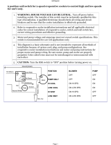
WARNING
Do not operate your air conditioning unit in water that is cooler than
38°F (3.3°C). Doing so could lead to
water freezing in the condenser coil which can cause damage to the unit.
1
4
2
3
5

Smart Touch Cabin Control Installation & Operations Manual INTRODUCTION
L-3380 ENGLISH 3
Figure 2: Smart Touch Main Screen
Smart Touch Main Screen Display Layout
1. Mode Selection icon
2. Home Screen icon
3. Up icon - Raise temperature set point
4. Fan Mode Selection icon
5. Fan Mode Indicator (Auto, high, medium, low)
6. Temperature Indicator (Inside, Set Point, Outside, Water, and Humidity)
7. Down icon - Lower temperature set point
8. Menu icon
9. Status & Schedule icon
10. Power icon
IMPORTANT PROGRAMMING NOTES TO INSTALLER AND END USER
1. If your air conditioning unit is Cool only (if it does not have a reversing valve), then you MUST select Cool Only Mode.
DO NOT select Automatic Mode for a Cool Only unit. If Automatic Mode is selected and the thermostat calls for heat,
the compressor will run. Since there is no reversing valve, the air conditioning unit will supply cool air when heating is
desired. Cool Only units do not heat. See “Modes of Operation” on page 9 for more information on how to set the
proper operating mode.
2. If your air conditioning unit has a Shaded-Pole (SP) fan motor instead of a Split-Capacitor (SC) High-Velocity (HV) fan
motor, you MUST program “SP” into General Setting 8, “Fan Motor Type”, before operating the equipment. The SP
units are recognizable by an overhanging blower motor. (The SC motor of an HV unit is inside the blower, and the unit
has “VTD” or “HV” in the model number.) Only reprogram this General Setting if you do NOT have an HV blower.
NOTICE
The system’s air sensor is located in the control’s display panel; therefore the display MUST be located on
an interior wall at eye level. It must NOT be located in direct sunlight or inside a cabinet. If these
conditions cannot be met, you must purchase the Optional Remote Air Sensor and install it in the return-
air stream.
NOTICE
Do not staple any sensor cables when mounting.
1
5
2
3
7
10
6
9
4
8

INSTALLING THE DISPLAY PANEL Smart Touch Cabin Control Installation & Operations Manual
4 L-3380 ENGLISH
MEMORY
When the Smart Touch losses power, the operating parameters are retained for up to 2 years. When power is restored, the
control resumes operating as last programmed. The Smart Touch has a battery backup. If the battery backup is removed, only
time and date settings will be lost.
NORMAL HEATING OR COOLING CYCLE
In Automatic Mode, heating and cooling are supplied as required. If cooling is required, the system will start a cooling cycle
when the cabin temperature exceeds the set point by 2°F (1.1°C) and will continue to cool until the temperature equals the set
point. (See “General Setting, Set Point Temperature Differential”, on page 13 for instructions on how to reduce this variation to
1°F [0.55°C].) The cabin temperature must drop below the set point by at least 4°F (2.2°C) in order for the system to switch from
cooling to heating. Similarly, if heating is required, the system will start a heating cycle when the cabin temperature is below the
set point by 2°F (1.1°C) and will continue to heat until the temperature equals the set point. The cabin temperature must exceed
the set point by at least 4°F (2.2°C) in order for the system to switch from heating to cooling. If you select Cool Mode, only
cooling is supplied. If you select Heat Mode, only heating is supplied. The cabin temperature in either mode is maintained within
2°F (1.1°C) of set point by default. (See “General Setting, Set Point Temperature Differential”, on page 13 for instructions on
how to reduce this variation to 1°F [0.55°C].) When the heating or cooling set point is satisfied, the compressor cycles off and
the fan returns to low speed. The fan speed remains constant if Manual Fan Speed is selected. For more information on this
feature, see “Modes of Operation” on page 9.
(For CW systems only)
When cooling or heating is required, the water valve will not open unless the water temperature is adequate. You can view
the water temperature by pressing the Temperature indicator icon until the Water temperature is displayed. The fan remains in
low speed until the adequate water temperature is available. Heat will be supplied when no heating is available (water
temperature is inadequate) only if the Optional Electric heater has been installed and programmed.
Adequate cooling or heating water temperature is defined by the Water Temperature Differential setting, under CW Control
Parameters. Its factory default is set at 15°F (8.3°C) differential from the ambient air temperature.
REVERSING VALVE OPERATION (FOR DX SYSTEMS ONLY)
The position of the reversing valve determines if the system is in Cool Mode or Heat Mode. In addition, the reversing valve is
programmed to toggle in these situations:
• When the system is running and heating or cooling is required, the reversing valve toggles to the opposite mode to
reduce the starting surge of the compressor.
• When a cooling or heating cycle is called for and if the system has been off for less than 5 minutes.
• When a cycle is interrupted from the display panel by pressing the Power icon or changing the set point.
Unnecessary valve toggling is limited to reduce reversing valve noise. You can totally eliminate valve toggling by programming
the minimum compressor staging delay to 5 minutes or greater (see “DX Operational Setting Compressor Start Delay” on
page 15 for more information). Power-On Reset, which occurs when the system is powered up, always initiates a valve toggle.
INSTALLING THE DISPLAY PANEL
CHOOSING THE LOCATION
Figure 3: Smart Touch Display Front Panel

Smart Touch Cabin Control Installation & Operations Manual INSTALLING THE DISPLAY PANEL
L-3380 ENGLISH 5
Before mounting the control panel, consider the location. The display panel’s built-in air sensor provides excellent room-air
temperature sensing when properly located and installed. For air sensor location see Figure 3. Mount the display panel on an
inside wall, slightly higher than mid-height of the cabin, in a location with freely circulating air where it can best sense average
temperature. Its distance from the air conditioner must be within the 15 ft (4.5 m) length of the display cable (custom lengths
available).
Do not mount the display in direct sunlight, near any heat-producing appliances or in a bulkhead where temperatures radiating
from behind the panel may affect performance. Do not mount the display in the supply-air stream. Do not mount the display
above or below a supply-air or return-air grille. Do not mount the display behind a door, in a corner, under a stairwell or any
place where there is no freely circulating air. If you cannot mount the display in a suitable location for accurately sensing room
temperature, install the optional remote air sensor.
MOUNTING THE DISPLAY
1. Make the cut-out for the display panel. Cut-out size is 2.900" (7.36 cm) wide by 2.165" (5.50 cm) high.
2. Plug one end of the display cable (8-pin connector) into the upper-right socket on the circuit board in the electric box
and the other end into the back of the display panel.
Figure 4: Smart Touch Display Mounting Dimensions
(Drawing not to scale – not a template)
3. Secure the display panel to the bulkhead using the four screws provided. Do not use a screw gun and do not over
tighten screws when mounting, because either method may damage the display.
4. When the display is securely mounted, mount the bezel over the display frame until it snaps into place.
Figure 5: Smart Touch Display Top View Mounting Dimensions

RECHARGEABLE BATTERY BACKUP Smart Touch Cabin Control Installation & Operations Manual
6 L-3380 ENGLISH
MOUNTING THE OPTIONAL SENSORS
REMOTE AIR SENSOR
Install the optional remote air sensor if the display cannot be mounted in a proper location for accurately sensing room
temperature. Installing the remote air sensor overrides the display’s built-in sensor. The standard cable length for the remote air
sensor is 7 ft (2.1 m).
1. Mount the remote air sensor in the return-air stream behind the opening of the return-air grille.
2. Plug its cable (6-pin connector) into the inside jack #J3 in the upper-left corner of the circuit board.
OUTSIDE AIR TEMPERATURE SENSOR
Install the optional outside air temperature sensor to monitor the temperature outside the cabin. Outside air sensor cables are
available in various lengths.
1. Mount the sensor outside but not in direct sunlight.
2. Plug its cable into the “OAT” plug #P6.
SERVICE SENSOR (FOR DX SYSTEMS ONLY)
Install the optional condenser coil temperature sensor into the “H2O OUT” plug #P5. Use of this sensor must be enabled by
going to DX Operational Setting and then Pump Sentry feature.
WATER INLET SENSOR (FOR CW SYSTEMS ONLY)
When using the AH Mode with a chilled-water air handler, plug the water-inlet sensor cable into the “H2O IN” plug #P4. Attach
the sensor to the chilled-water inlet on the air handler. Ensure that the sensor makes good contact with the copper pipe. DO
NOT attach to rubber hose.
SEAWATER TEMPERATURE SENSOR - OPTIONAL (FOR DX SYSTEMS ONLY)
Install the optional seawater temperature sensor to monitor the temperature of the seawater feeding the air conditioner. Ensure
that the sensor is in direct contact with the copper pipe and use thermal mastic to ensure good heat transfer. Strap the sensor
wire in place for strain relief and to prevent the sensor from being accidentally removed. Plug the sensor’s 2-pin connector into
the “Loop Water Out” (blue) socket located on the circuit board.
HUMIDITY SENSOR - OPTIONAL
Install the optional humidity/temperature combo sensor to monitor the relative humidity of the cabin. Locate the sensor in the
same location as the ambient air temperature sensor. Plug the combo sensor’s 6-pin connector into the inside temperature
socket located on the edge of the circuit board. The control board automatically detects the presence of this combo sensor and
immediately starts measuring humidity.
RECHARGEABLE BATTERY BACKUP
The Smart Touch comes with a rechargeable battery. The battery recharges whenever the control is powered, similar to a
computer motherboard battery, so there should never be a need to install or replace the backup battery. When the Smart Touch
is plugged into a control that is powered up, the battery is not being drained. Only when the AC power to the control board is
powered off is the battery being drained in the Smart Touch itself. The battery backup will last over two years of "powered-off
time” or inactivity.
When the battery drains due to inactivity, the only information that is lost is the date and time. No other information is lost. Also,
the screen lock PIN will be reset to its default ("1234") when the battery gets drained. All other programming parameters,
calibrations, program scheduler settings, etc., are retained in flash memory forever and do not use the battery power at all.
When the battery drains, there will be no visible indication on the display during normal power up. What will happen is that upon
a subsequent (AC) power down and power up, the user will immediately be prompted to set the date/time setting. This is their
indication that the battery got drained due to inactivity.

Smart Touch Cabin Control Installation & Operations Manual OPERATION
L-3380 ENGLISH 7
OPERATION
OPERATOR CONTROLS AND DISPLAY PANEL
HOME SCREEN ICON FUNCTIONS
Figure 6: Smart Touch Home Screen Icon Functions
1. Power On/Off Icon - Press and release to toggle between the On and Off Modes.
2. Up Icon - Press and release to display the set point. Press and release the Up icon as many times as desired to
increase the set point. Set point increases one degree each time the icon is pressed.
3. Down Icon - Press and release to display the set point. Press and release the Down icon as many times as desired to
decrease the set point.
4. More Icon - Press and release to change display to Main Screen.
5. Status Icon - Shows the system status. (OFF, PENDING, ACTIVE, STANDBY, FAULT)
6. Temperature Indicator Icon - Press and release to select from Set Point(s), Inside, Outside, Service/Water
Temperatures, and Humidity.
7. Force Sleep Mode Icon - Press and release to force sleep mode to initiate immediately, if enabled (i.e. Sleep Delay
not equal to OFF)
7
4
2
3
1
6
5

OPERATION Smart Touch Cabin Control Installation & Operations Manual
8 L-3380 ENGLISH
MAIN SCREEN ICON FUNCTIONS
Figure 7: Smart Touch Main Screen Icon Functions
1. Mode Icon Indicator - The Mode icon indicates the current mode active. Press and release to select one of the four
operating modes. Continue to press and release the Mode Icon until the desired operating mode is reached. The mode
icons (Auto, Cool, Heat, Auxiliary Heat, or Moisture) light to indicate which mode is selected. It shows 5 different icons
depending on the mode:
• Auto Mode Icon Indicator - The Auto Mode icon is shown when the system is in Automatic Mode, which switches
to cooling or heating as required to satisfy the temperature set point.
• Cool Mode Indicator - The Cool Mode icon is shown when the cool-only mode is selected or when the unit is in
an Automatic Mode cooling cycle.
• Heat Mode Indicator - The Heat Mode icon is shown when the heat-only mode is selected or when the unit is in
an Automatic Mode heating cycle.
• Auxiliary Heat Mode Indicator - The Auxiliary Heat Mode icon is shown when the Aux heat-only mode is
selected or when the unit is in an Automatic Mode Auxiliary heating cycle.
• Moisture Mode Indicator - The Moisture Mode icon is shown when the Moisture Mode is selected. This mode
controls humidity during periods when the vessel is unoccupied.
2. Fan Mode Indicator - Auto or Manual Indicator icon shows when Automatic fan speed or either of the three Manual
speeds are selected.
3. Power Icon - Press and release to toggle between the On and Off Modes.
4. Up Icon - Press and release to display the set point. Press and release the Up icon as many times as desired to
increase the set point. Set point increases one degree each time the icon is pressed.
5. Down Icon - Press and release to display the set point. Press and release the Down icon as many times as desired to
decrease the set point.
6. Fan Icon - Fan-speed operation is automatic, allowing fan speed to decrease as set-point temperature is approached
in the Cool Mode. The fan operates at low speed when set point is satisfied. Normally the automatic fan speed
operation is reversed in the Heating Mode; however, you can program the fan to operate the same as in the Cooling
Mode. Press the Fan icon to select manual fan speeds if you want to override automatic operation. You can program
the fan to run only during a cool or heat cycle; otherwise the fan runs constantly. Press and release to advance from
Auto Fan to Manual Fan. Press and release the Fan Icon to advance the manual fan speeds, from low to high. Press
and release again to return to the Automatic Fan mode. The selected Fan Mode is indicated by the Fan Indicator icon.
You can change the fan operating mode from Continuous to Cycled by going to Main Menu, Control Parameters,
General Settings, and then Fan Operate Mode.
7. Temperature Set Point and Humidy Indicator Icon - Press and release to select from Set point(s), Inside, Outside,
or Service/Water temperatures and Humidity.
8. Main Menu Icon - Press the Menu icon to show the Main Menu page.
9. Status/Schedule Icon - Press the Status/Schedule icon to view any fault occurring in the system.
10. Dometic/Date/Time Icon - This shows the date and time if enabled. To enable it, press Menu, Date/Time Menu, and
then Date/Time Display.
1
8
4
5
3
6
10
7
9
2

Smart Touch Cabin Control Installation & Operations Manual MODES OF OPERATION
L-3380 ENGLISH 9
MODES OF OPERATION
OFF MODE
When the control is in Off Mode, all control outputs are turned off. All settings are saved in nonvolatile memory.
ON MODE
When the control is in On Mode, power is supplied to the appropriate outputs and the display indicates the current state of
operation. The operating and program parameters resume based on those last stored when the unit was operating.
AUTOMATIC MODE
When Automatic Mode is selected, the system provides both heating and cooling as required. The Auto Mode icon is shown.
Cabin temperature in a given mode is maintained within 2°F (1.1°C) of set point by default. (See “General Settings, Set Point
Temperature Differential” on page 13 for instructions on how to reduce this variation to 1°F [0.55°C].) If the system was most
recently cooling, the cabin temperature must drop below the set point by at least 4°F (2.2°C) in order for the system to switch
from cooling to heating. Similarly, if the system was most recently heating, the cabin temperature must exceed the set point by
at least 4°F (2.2°C) in order for the system to switch from heating to cooling. This behavior prevents small temperature
overshoots from causing the system to switch between heating and cooling when it is not necessary.
COOL MODE
When Cool Mode is selected, the Cooling mode icon is shown and only the cooling system operates as required. If the ambient
temperature drops below the set point, the system will not automatically switch to the Heat Mode.
HEAT MODE
When Heat Mode is selected, the Heating mode icon is shown and only the heating system operates as required. If the ambient
temperature rises above the set point, the system will not automatically switch to the Cool Mode.
MOISTURE MODE
Use Moisture Mode to help control humidity while you are away from the boat or away from a particular cabin. While the control
is in the On Mode, press the Mode icon until the Moisture Mode icon is shown. Once Moisture Mode is enabled, the fan
circulates the air for 30 minutes. During this time, the air temperature is sampled and entered into memory. After 30 minutes, a
cooling cycle starts and continues until the temperature is lowered 2°F (1.1°C) or until the cooling cycle runs a maximum of one
hour.
Four hours after the temperature is satisfied or the cooling cycle times out, this cycle repeats. Moisture Mode will also prevent
your boat or a particular cabin from dropping below a minimum temperature as a means to prevent the contents from freezing.
When the temperature drops low, eliminating moisture may become less of a concern and maintaining some minimum
temperature may become more important. After the 30-minute fan circulation, if the temperature is at or above the factory
default setting of 50°F (10°C), a cooling cycle is started and runs as described above. However, if the temperature is below 50°F
(10°C), a heating cycle will be started instead. The heating cycle will continue until the temperature reaches 50°F (10°C) or until
the heating cycle runs a maximum of one hour. Four hours after the temperature is satisfied or the cooling/heating cycle times
out, the entire cycle repeats, each time determining whether cooling or heating is required. See “General Settings, Humidity
Mode Minimum Temperature” on page 13 for more information on how to adjust the 50°F (10°C) factory default to a different
temperature that may better suit your particular requirements. The adjustment range is 40°F (4.4°C) to 75°F (23.9°C). NOTE for
DX systems only: On systems configured with reverse-cycle heat, the Moisture Mode heat cycle will not be allowed to run when
the ambient temperature is below 40°F (4.4°C). This is necessary to protect the condenser coil from freezing. Systems
configured with electric heat will be allowed to run the Moisture Mode heat cycle regardless of the room temperature.
DEHUMIDIFICATION MODE INDICATOR
The word DEHUMIDIFY displays when the control is in Dehumidification Mode. It flashes if optional humidity sensor is
connected and operating in the Cooling Mode.
FAN MODES
Automatic Fan Mode
Smart Touch has three automatic fan speeds available: High, Medium and Low. Automatic Fan Mode allows the Smart Touch to
determine the required fan speed based on temperature differential. This permits a balance between the most efficient
temperature control and slower, quieter fan speeds. To select Automatic Fan Mode, press and release the Fan icon until the
word “Auto” above the fan speed graph is shown.

MODES OF OPERATION Smart Touch Cabin Control Installation & Operations Manual
10 L-3380 ENGLISH
Manual Fan Mode
There are three manual fan speeds available: High, Medium and Low. Manual Fan Mode allows you to select and maintain a
desired fan speed. When a Manual Fan speed has been selected, the speed is indicated by the Fan Speed bar graph. The bar
level will increase as you increase the speed setting. Press and release the Fan icon until the desired speed is reached.
Fan-Only Mode
Use the Fan-Only Mode to operate the fan for air circulation when no cooling or heating is desired. From the Off Mode press
and release the Fan icon to start Low fan speed. Press and release again to select Medium fan speed. Press and release a third
time to select High fan speed. Press and release a fourth time to turn off the fan or place it in Auto mode. Turning on the control
will revert the fan to the Automatic Mode or the last selected manual fan setting.
MAIN MENU
Use the Main Menu settings to adjust operating parameters for your particular needs. Main Menu is also used to fine-tune the
system for the most efficient operation within an installation. (Variables such as ducting, sensor location, and system layout
affect system operation.) The control has factory default settings stored in permanent memory that can be recalled. For this see
Main Menu, Control Parameters, and then Recall Defaults. Reprogrammed new settings can be saved as Memorized settings
and can be recalled and saved at any time. See “Main Menu, Control Parameters, Memorize Settings, and Recall Memorized”
on page 17 for details.
Main Menu Screens Layout
Figure 8: Smart Touch Main Menu Screen Layout
1. Home Icon - Press this icon at any time to return to the Home Screen
2. Back Icon - Press this icon to return to the previous screen
3. Scroll Down Icon - Press this icon to go to the next set of settings
4. Main Menu Selection Options - Press any icon to modify the selected option
NOTICE
For DX systems only: If your air conditioning unit is Cool only (if it does not have a reversing valve) then Cool Mode
MUST be selected. DO NOT set to Automatic Mode for a Cool-Only unit. If Automatic Mode is selected and the
thermostat calls for heat, the compressor will run. Since there is no reversing valve, the air conditioning unit will
supply cool air when heating is desired. Cool-Only units do not heat.
1
3
2
4

Smart Touch Cabin Control Installation & Operations Manual MODES OF OPERATION
L-3380 ENGLISH 11
General Settings Screen Icon Layout
Figure 9: Smart Touch General Settings Screen Icon Layout
1. Home Icon - Press this icon at any time to return to the Home Screen
2. Back Icon - Press this icon to return to the previous screen
3. Up Icon - Press the icon to increase the setting
4. Down Icon - Press the icon to decrease the setting
5. Save Icon - Press this icon save the desired setting changes
CONTROL PARAMETERS
General Settings
Figure 10: Smart Touch
General Settings Page 1 of 8
To access the General Settings, go to Main Menu, Control Parameters, and the
General Settings.
1. High Fan Speed Values for the upper fan-speed limit range from 35 to 95.
Set a higher number to increase the fan speed or a lower number to slow the
fan speed.
2. Medium Fan Speed Values for the upper fan-speed limit range from 35 to
95. Set a higher number to increase the fan speed or a lower number to slow
the fan speed.
3. Low Fan Speed Values for the lower fan-speed limit range from 32 to 85.
Set a higher number to increase the fan speed or a lower number to slow the
fan speed.
4. Inside Temp Calibration This setting calibrates the ambient sensor within a range of ±10°F. Adjust this parameter to
display the correct room temperature reading. Note that setting increments are in °F even when the control is set to
display °C.
Figure 11: Smart Touch
General Settings Page 2 of 8
5. Temperature Units (°F/°C/Auto) The default setting is °F. Select °C for
Celsius. (Celsius readings are displayed in tenths, for example 22.2°). Auto
corresponds to “automatic by line frequency”, where 60 Hz automatically
sets the unit to Fahrenheit or °F, and 50 Hz automatically sets the unit to
Celsius or °C.
6. Reversed Fan Speed in Heat Reverse Automatic Fan Speeds during
Heating lets you automatically reverse the fan speed during Heat Mode. This
improves heat output in cooler climates. The fan will speed up as the set
point is approached. Lowering the fan speed when the cabin is cold
increases head pressure and helps raise supply temperature. Increasing the
fan speed as the set point is approached also reduces unnecessary high-
pressure faults. The fan switches to low speed when the set point is satisfied and the compressor cycles off. The fan
can be programmed to operate the same as in cooling by selecting the Off option, which represents normal fan
operation during reverse-cycle heating.
1
3
4
2
5

MODES OF OPERATION Smart Touch Cabin Control Installation & Operations Manual
12 L-3380 ENGLISH
7. Electric Heat and Auxiliary Heat Option (ELEC=electric heat, AUX HEAT=reverse-cycle & auxiliary electric heat,
Off=Use of reverse-cycle heat)
For DX Applications
ELECTRIC HEAT Units not equipped with reverse-cycle heat may have an electric heater added. Set to “ELEC” for the
electric heat option or “OFF” to disable. Reversing-valve toggle (energizing of reversing-valve output) will not occur
prior to compressor start-up if the electric heat option is selected. For legacy PPIO boards, the valve output and
electric heat relay will both be energized when DX electric heat is called for. Since the valve-relay output only supports
a maximum of 15 amps at 115V AC or 10 amps at 230V AC of resistive load, when installing an optional electric heater
that exceeds this load, it is necessary to install an additional contactor that is rated to handle the full load of the electric
heater.
AUX HEAT= Reverse-cycle & Auxiliary electric heat (Only available for following firmwares or newer: SmartTouch A25
connected to U-Board R3V36, and SmartTouch A26 connected to U-board Two 01T07) The control board allows
operation of an optional auxiliary (aux) electric heater output. If an auxiliary electric heater is not installed, select “OFF”
to disable the auxiliary electric heater. Selecting “AUX HEAT” allows the auxiliary electric heater to be operated at the
same time as the reverse-cycle heating when the dehumidification feature is active and required. Auxiliary heat output
will also operate when using the optional Seawater Low Limit Adjustment or AutoChangeover feature, if enabled. See
DX Setting # 8.
For CW Applications
ELECTRIC HEAT (ELEC=use electric heat and/or hydronic heat, OFF=use only hydronic heat. Factory Default: ELEC)
The control board allows operation of an optional electric heater. The default for this feature is “ELEC” indicating
electric heat is enabled and installed. If an electric heater is not installed, select “OFF” to disable the electric heater.
The compressor and spade terminal outputs will be energized when CW electric heat is called for. Selecting “ELEC”
allows the electric heater to be operated at the same time as the hydronic valve when the dehumidification feature is
active and required.
Please consult with Dometic Customer Service or with an authorized service technician for assistance.
8. Fan Motor Type
The Split Capacitor default setting is correct for air conditioning units with high-velocity blowers. Only
change the setting to Shaded Pole if your unit has a Shaded Pole fan motor, recognizable by a blower-motor overhang.
(The Split Capacitor motor of a high-velocity unit is inside the blower, and the unit has “VTD” or “HV” in the model number.)
9. Filter Hours Setting
Reminder for air filter cleaning or replacement is determined by the number of hours of fan operation.
Filter Hours Setting can be set as a reminder to clean or replace the unit’s air filter. Select the number of operating hours
until the filter reminder appears. Parameter choices are between 100 hours and 2500 hours. Dometic recommends that you
check the air filter at least every 500 hours of operation. The default setting is off. Once set, the timer keeps track of the total
amount of run hours that the fan accumulates. Once the timer setting is reached, flashes briefly on the status icon until it is
cleared. Display of the room temperature continues and the normal operation of the system is not affected. The reminder
can only be cleared and the timer reset via General Setting, and then Filter Hours Setting.
Figure 12: Smart Touch
General Settings Page 3 of 8
10. Filter Hours Reset The Filter Hour Reset setting shows the number of filter
reminder hours accumulated and allows clearing via a CLR icon. This
parameter displays the current elapsed time in hours since the timer was
started or reset. To clear the reminder, press the CLR icon. This resets the
value to 0 and restarts the timer.
11. CAN Bus Unit ID This parameter selection icon is grayed out whenever the
Smart Touch is not plugged into a control board with the CAN bus
daughterboard option. In other words, this parameter displays only when
CAN-bus network capability is available and the Smart Touch is plugged into
a networked control board. This parameter does not display when the Smart
Touch is plugged into a standard control board. Each control on the same CAN-bus network must be assigned a
unique Unit ID (0 -255). For example, the control that is set to 5 will respond to commands with a destination address
of 5.

Smart Touch Cabin Control Installation & Operations Manual MODES OF OPERATION
L-3380 ENGLISH 13
Figure 13: Smart Touch
General Settings Page 4 of 8
12. CAN Bus Group ID This parameter selection icon is grayed out whenever
the Smart Touch is not plugged into a control board with the CAN bus
daughterboard option. In other words, this parameter displays only when
CAN-bus network capability is available and the Smart Touch is plugged into
a networked control board. This parameter does not display when the Smart
Touch is plugged into a standard control board. Assign the address for the
control’s CAN-bus network group (0 - 255). This number should be unique
and different than any CAN-bus Unit ID. For example, all controls that are set
to 100 will respond to commands with a destination address of 100 (in
addition to responding to commands that target their individual Unit IDs).
13. Voltmeter Calibration This parameter allows adjustment of the line voltage reading as measured by the Smart Touch.
This setting displays the voltage being read by the power and logic circuit board. It displays a live reading of the
voltage and can be manipulated by pressing the Up or Down icons. Calibrating this parameter provides a more
accurate voltage level when calculating low voltage. Use a reliable voltmeter as a reference when adjusting this
parameter.
Figure 14: Smart Touch
General Settings Page 5 of 8
14. Set Point Temperature Differential This parameter is the temperature
differential in Fahrenheit for all modes of operation: Automatic, Cool, or Heat.
Refer to “Modes of Operation” on page 9 for more information on how this
parameter affects these modes. By default, this parameter setting is 2°F
(1.1°C). It can be set to either 1°F (0.55°C) or 2°F (1.1°C). Setting this
parameter to 1°F (0.55°C) will result in the control maintaining the room
temperature closer to the desired set point. However, this may result in more
frequent shorter-duration cooling or heating cycles. In most cases, the
factory default of 2°F (1.1°C) is adequate for maintaining a comfortable
temperature variation around the desired set point. If you desire less
variation in temperature, set this parameter to 1°F (0.55°C).
15. Humidity Mode Min Temp This parameter is the minimum room temperature in Fahrenheit for which Moisture Mode
will run a cooling cycle to remove moisture from the air. If the room temperature is below this parameter setting,
Moisture Mode will run a heating cycle instead. By default, this parameter is set to 50°F (10°C), and it can be adjusted
between 40°F (4.4°C) to 75°F (23.9°C). Please refer to the description of “Moisture Mode” on page 9 for more
information on how Moisture Mode functions and utilizes this parameter.
Figure 15: Smart Touch
Outside Temperature Indicator
16. Auto Fan Speed Temp Differential This setting sets the incremental
differential (with cumulative steps) between the ambient temperature and the
set point temperature at which the fan speed will increment to the next
speed. Note that there is 1°F hysteresis in the auto fan speed differential to
prevent the speed from changing if the room temperature changes by a
fractional degree causing speed fluctuations. Also General Settings
Reversed Fan Speeds in Heat, and Set Point Temperature Differential, both
have an effect on the operation of the auto fan speed.

MODES OF OPERATION Smart Touch Cabin Control Installation & Operations Manual
14 L-3380 ENGLISH
Figure 16: Smart Touch
General Settings Page 6 of 8
17. Supply Air Temp Limit Enabling this parameter has no effect unless
General Setting Electric Heat Option or Auxiliary Heat Option is also enabled
(set to “On”). Use of this parameter requires that the OAT sensor is placed in
the supply air stream immediately downstream of the blower discharge. This
setting is the maximum the supply air discharge temperature will allow. Heat
mode will be shut down if the temperature of this sensor exceeds the
programmed setpoint. Heat mode will be restored once a 10°F hysteresis
has been satisfied. Heat mode will also be restored if power is cycled to the
control and the OAT sensor temperature is less than the setting but still
within the hysteresis. There is no fault indication when this condition occurs
and no lock-out. The discharge temperature can be displayed by pressing
the temperature icon until the temperature title shows Outside (same as viewing the Outside Air Temperature).
18. DX/CW Mode Selection
Choosing “Set by Jumper” preserves the status of the control board operation where if the
“Removed for CW” jumper on the main control board is not removed, the Smart Touch will operate in DX mode, and if the
jumper is removed, the Smart Touch will operate in CW mode. The other choices for this parameter allow the jumper to
be overridden, if desired.
Figure 17: Smart Touch
General Settings Page 7 of 8
19. Inside Temp Sensor Selection If the alternate air temperature sensor is
plugged into the control board, it is used as the inside temperature, and if it is
not plugged in, the built-in display temperature sensor is used for inside
temperature. This parameter allows this behavior to be overridden if desired.
20. Fan Operational Mode The fan can be set to run continuously whenever the
system is turned on, or it can be set to cycle on and off in conjunction with
the cooling or heating cycles.
21. Dual Temp Set Points When Off, there is only one common set point, which
is adjustable and used for both heating and cooling. When On, two separate
set points are settable and used, one for cooling and one for heating.
Figure 18: Smart Touch
General Settings Page 8 of 8
22. Humidity Sensor Limit Adjustment
For DX applications (Optional; Factory Default: 60% RH) If the optional
humidity sensor is connected to the control board, this feature allows the
system to dehumidify with auxiliary electric heat (if auxiliary electric heat is
installed and enabled) when the cabin humidity rises above 60% (default)
relative humidity (RH). The electric heater will cycle on and off to maintain
set point while the compressor turns on to dehumidify. When the room
temperature has reached the set point, the compressor will remain on. The
display will indicate that the system is in "Dehumidify" mode. If the
temperature decreases by one degree, the auxiliary electric heat will turn on
to maintain the set point and the compressor will remain on. If the temperature increases back to set point, the electric
heat will turn off. If the temperature increases one degree above the set point, the compressor will remain on. This
operation will continue until the cabin’s relative humidity is less than 60% (default). If an electric heater is not installed,
the compressor run time will extend by operating to 1°F lower than set point. This cycle continues until the cabin’s
relative humidity is less than 60% (default). The range of adjustment is 50% to 80% RH.
For CW applications: (Optional; Factory Default: 60% RH) If the optional humidity sensor is connected to the control
board, this feature allows the system to dehumidify with electric heat (if electric heat is installed and enabled) when the
cabin humidity rises above 60% (default) relative humidity (RH). The electric heater will cycle on and off to maintain set
point while the bypass valve opens to allow cold loop water to enter the air handler coil to dehumidify. This operation
continues until the cabin’s relative humidity is less than 60% (default). If an electric heater is not installed, the bypass
valve’s on time will extend by operating to 1°F lower than set point. This cycle continues until the cabin’s relative
humidity is less than 60% (default). The range of adjustment is 50% to 80% RH.

Smart Touch Cabin Control Installation & Operations Manual MODES OF OPERATION
L-3380 ENGLISH 15
DX Operational Settings
1. Compressor Start Delay
The compressor staging delay is for installations where more than one system operates from
the same power source. Setting different staging delays allows compressors to start at different times when power is
interrupted. Stage the units at least 5 seconds apart. Minimum delay is 5 seconds and maximum is 135 seconds.
2. Failsafe To protect the equipment, certain fault conditions trigger a lockout: The control shuts down and will not restart
until the fault is repaired. The lockout condition depends on a combination of the failsafe level you have programmed
as well as the type of fault detected.
There are 4 different Failsafe levels to choose from.
a. Faults Not Detected - This level provides minimal failsafe protection and is not recommended. Only the “Air
Sensor Failure” fault is detected and displayed. The control shuts down and will not restart until the fault is
repaired. When the fault is repaired the control restarts after a 2-minute delay.
b. Faults Detected But Not Displayed - This level provides the failsafe actions of Faults Not Detected, plus all
other faults are detected but not displayed. The system shuts down for 2 minutes or until the fault is cleared,
whichever is longer. The system restarts when the fault is cleared.
c. Faults Detected and Displayed - This level provides the failsafe actions of the previous two levels, plus all faults
are displayed. The system shuts down for 2 minutes or until the fault is cleared, whichever is longer. The system
restarts when the fault is cleared.
d. Faults Detected and Displayed with Lockout - This level provides the failsafe actions of previous 3 levels, plus
the system will lockout after four consecutive High Pressure Fault, Low Pressure Fault, or High Water
Temperature in Condenser Coil faults, and you can clear the lockout. The system shuts down for 2 minutes or until
the fault is cleared, whichever is longer. To clear the lockout, press the Power icon once to Off Mode and press it
again to On Mode.
Figure 19: Smart Touch
DX Settings Page 1 of 3
3. Low Voltage Monitor The Smart Touch has a built-in voltmeter circuit that
monitors the AC input voltage. Depending on whether the input power supply
is 100V AC or 115V AC or 230V AC, this parameter can be set to “Off”, 75-
120V AC for 100-115V AC input power, or 175-240V AC for 230V AC input
power. The factory default setting is Off. When this parameter is set to 75-
120 or 175-240V AC, the Smart Touch checks the AC input voltage prior to
each cooling or heating cycle and prevents the compressor from starting if
the voltage is less than the one set. This provides extra protection for the
compressor and components within the system during low voltage
(brownout) conditions. If this low voltage condition occurs, the fault code Low
AC Voltage appears in the Status icon in the Main display. The fault will
continue until the AC input voltage rises above selected voltage value, at which time the Low AC Voltage fault code
clears automatically and the cooling or heating cycle will commence. After the compressor is started, the low voltage
monitor continues to check the AC input voltage. If it drops below the specified setting and remains below for 5
minutes, the system will shut down and the Low AC Voltage fault will be displayed. The system will remain shut down
until the voltage goes back above the specified setting. Once the voltage is restored, after the normal fault recovery
delay, the system will be restarted. As with all faults, system lockout (sustained shutdown) will occur after the fourth
consecutive Low AC Voltage fault. See Fault Handling, History & Run Hours for further details on system lockout.
Figure 20: Smart Touch
DX Settings Page 2 of 3
4. De-Ice Cycle The de-icing cycle prevents ice buildup on the evaporator coil
during extended periods of cooling operation. Installation variables such as
grille sizes, length of ducting, insulation, and ambient temperatures
determine the run time required to achieve set point. Factors that
substantially increase run time include operating the system with hatches
and doors open and programming an unrealistic set point (e.g. 65°F/18.3°C).
Such situations can cause the evaporator to form ice on warm humid days.
De-icing is accomplished by closely monitoring the room air temperature in
10-minute intervals during a cooling cycle. Depending on the parameter
value and the change in room temperature during these monitoring intervals,
the control performs various actions to prevent ice from forming or to melt ice

MODES OF OPERATION Smart Touch Cabin Control Installation & Operations Manual
16 L-3380 ENGLISH
that has already formed. This is accomplished by short compressor shutdown periods combined with a one-speed
increase in fan speed and by periodic Heat Mode cycles with the fan turned off. The parameter setting for the de-icing
feature depends on whether you are using the optional alternate air-temperature sensor or the display’s built-in room
air-temperature sensor. Installation of an optional alternate air temperature sensor (located in the return air path)
greatly increases the effectiveness of the de-icing feature, and this option should be considered whenever the display
sensor cannot read the room temperature accurately.
• If using an optional alternate air temperature sensor, set this parameter to Enable with 5°F/3°C Sensor
Differential to turn the de-icing feature on, or to Off to disable.
• If using the display’s built-in room air temperature sensor, this feature has 2 selectable behavior modes. Both
modes attempt to compensate for any temperature discrepancy the display sensor experiences. (Although
discrepancy is not typical, installation variables such as where the display is placed inside the room – near an
open door or in direct sunlight – can affect how accurately it reads the actual room temperature.) Set this
parameter to or Enable with 5°F/3°C Sensor Differential to assume the display sensor may be reading the room
temperature as much as 5°F (2.8°C) greater than the actual evaporator temperature (standard). For more extreme
installations, set this parameter to Enable with 7°F/4°C Sensor Differential to assume the display sensor may be
reading the room temperature as much as 7°F (3.9°C) greater than the actual evaporator temperature. The setting
of the second option should only be used if the selection of the first option does not prevent evaporator ice from
forming.
5. Pump Sentry Smart Touch can be equipped with an optional temperature sensor that is used to monitor the
condenser coil temperature. The sensor is plugged into the “H20 OUT” sensor plug. The Pump Sentry setting can be
programmed for a temperature between 100 and 150°F (37.8 and 65.6°C), depending on seawater temperature and
the system type. (Note that setting increments are in °F even when the control is set to display °C.) Connect the water
sensor to the condenser coil outlet and insulate it. When the coil temperature rises above the programmed value, the
pump and compressor are shut down and “Pump Sentry Fault” flashes in the display.
6. Pump Operate Mode Cycle pump with Compressor to increase pump life and conserve electricity. The pump can be
programmed to cycle on and off with the compressor. The pump can also be programmed to operate continuously
whenever power is applied. To program the pump for continuous operation, set the setting to Continuous.
Figure 21: Smart Touch
DX Settings Page 3 of 3
7. Low Pressure Detection When selecting “Set by Jumper”, if the “Enable
LP” jumper on the main control board is not removed, the low pressure
switch will be disabled, and if the jumper is removed the low pressure switch
will be enabled. Choosing “Disabled (Use Caution)” will force the Smart
Touch to ignore the low pressure switch, treating it as disabled even if the
jumper is removed. This should only be done when advised by Dometic
Customer Service. As with all faults, system lockout (sustained shutdown)
will occur after the fourth consecutive Low Pressure fault.
8. Seawater Low Limit Adjustment (Optional; Factory Default: 40°F) If the
optional seawater sensor is connected to the control board, this feature
allows the system to switch from reverse-cycle heat to electric heat (if an auxiliary electric heater is installed and
enabled) if the seawater temperature drops below 40°F (4.4°C) (default) and the reverse-cycle heat has operated
more than five minutes. Once the seawater rises 3°F above the Seawater Low Limit temperature, the system returns to
reverse-cycle heating. If an aux heater is not installed, the system will shut down and flash “LO” then “SE” when the
seawater drops below 40°F (4.4°C) (default). Once the seawater rises 3°F above the Seawater Low Limit temperature,
the system goes back into reverse-cycle heating and stops flashing “LO” then “SE”. The range of adjustment is 35°F to
50°F.

Smart Touch Cabin Control Installation & Operations Manual MODES OF OPERATION
L-3380 ENGLISH 17
CW Operational Settings
Figure 22: Smart Touch CW Settings Ambient
Air to Water Temperature Differential
1. Water Valve Force Open This parameter
opens the water valve to bleed air from the
system. “On” forces the valve open for 4 hours
while the Smart Touch control is turned off. If
Cool mode is activated or if AC power is
interrupted to the control’s electric box during
this 4-hour period, this valve override feature is
canceled. You can return the valve to normal
operation at any time by changing the setting
back to “Off”.
2. Water Temp Differential This parameter sets
the temperature differential between ambient
air temperature and hydronic water
temperature that controls the water valve. For
example, selecting 10°F opens the valve when
water temperature is 10 degrees less than
ambient in cooling mode and 10°F greater than
ambient in the heating mode. Careful selection
of the temperature differential can fully utilize
the ship’s heating and cooling resources. For
example, while in cooling mode and using a 10 degree value, the valve will open to allow some cooling while the
hydronic system is coming down to temperature. See the Figure 22 for a graphical explanation of this parameter.
Figure 23: Smart Touch
CW Settings Page 1 of 1
Memorize Settings
If you want new parameters to be the program defaults, adjust the parameters to the
desired settings, and then go to Memorize Settings and press the Save icon. This
memorizes the new settings as program defaults. To return to the factory default
settings, refer to the Recall Factory Defaults listed.
Recall Memorized Settings
If you want to restore the last memorized default settings, then go to Recall
Memorized and press the Save Icon. The memorized default settings are restored. To
return to the factory default settings, refer to the Recall Factory Defaults listed.
Figure 24: Smart Touch
Control Parameters Page 2 of 2
Recall Factory Default Settings
The system's default parameters may be changed by the installing dealer or end user.
Once new values are entered and memorized, the factory defaults are overwritten and
the new parameters become the default values. If you want to restore the original factory
default parameters manually, then go to Recall Defaults and press the Save Icon.
NOTE: If you have any reason to contact Dometic about the system or
programming the control, you must have the software identification number
and air conditioning unit serial number available. The serial number may be
found on the dataplate label.
NOTICE
If you have any programming problems or confusion occurs, reset the Memorized Default Settings and try
again.

MODES OF OPERATION Smart Touch Cabin Control Installation & Operations Manual
18 L-3380 ENGLISH
PROGRAM SCHEDULER
Program Scheduler lets you start and/or stop the A/C unit at specific time, day of the week, mode and temperature set point. To
access the Program Scheduler, go to Main Menu, Program Scheduler, and select the setting to modify.
Figure 25: Smart Touch Program
Scheduler Pages 1 and 2 of 4
1. Scheduler mode As soon as the Program Scheduler is enabled, it will
immediately start applying the programs as defined in the various day
settings.
2. Program: Mon-Fri
3. Program: Sat-Sun
4. Program: Day of the Week (Seven different programs)
Each program has a mode, time, cooling set point, and heating set point (if dual set
points are enabled). The Mode choices are Off, Cool, Heat, Auto, Dehumidify. If Dual
Set Points is selected, the cooling set point is settable for Cool and Auto, and the
heating set point is settable for Heat and Auto. Set points are not settable for Off or
Dehumidify.
Figure 26: Smart Touch
Program #1 Scheduler Page 1 of 4
DATE/TIME MENU
Date/Time Menu lets you set the display time, its format, and optional display on Main
Screen. To access the Date/Time Menu, go to Main Menu, and Date/Time Menu, and
select the setting to modify.
Figure 27: Smart Touch
Date and Time Settings
1. Date/Time Display Choose between On or Off to control the display of date/
time on Main Screen only.
2. Date/Time Format Choose between Automatic by Line Freq (60Hz line
frequency results in M/D/Y 12-hour format, and 50Hz line frequency results
in D/M/Y 24-hour format), M/D/Y 12-hour, or D/M/Y 24-hour.
3. Date/Time Settings This setting allows date and time modification. Each
date and time value are individually editable. The day of the week will
automatically be calculated based upon the date.
/