Page is loading ...

InstallatIon GuIde
sCs-1R
seCuRIty ContRol ReCeIveR
DMP Receiver Help Line
Technical Service
1-888-436-7832
International
1-417-831-9362
After hours receiver emergencies
1-417-831-2866

Security Control Receiver
Model SCS-1R
Installation Guide
© 2003-2008 Digital Monitoring Products, Inc.
Information furnished by DMP is believed to be accurate and reliable.
This information is subject to change without notice.

SCS-1R Installation Guide Digital Monitoring Products
i
Table of ConTenTs
Operator’s Quick Reference
Acknowledging an Alarm Signal .............................................. 1
LED Indicators ...................................................................... 1
System Overview
Description ........................................................................... 2
Function ............................................................................... 2
32-Character LCD Membrane Keypad ...................................... 2
Printer .................................................................................. 2
Additional Messages .............................................................. 2
24-Hour Recall Tests .............................................................. 2
Line Capacity ........................................................................ 2
Number of Standard or Encrypted Line Security Network Accounts
..... 2
Opening and Closing Signals .................................................. 2
System Block Diagram ........................................................... 3
Installation Checklist
SCS-1R Faceplate .................................................................. 4
Earth Ground ........................................................................ 4
Location of Circuit Boards ...................................................... 4
SCS-208 Power Cord .............................................................. 4
Phone Lines .......................................................................... 4
Network Connection .............................................................. 4
AC Power .............................................................................. 4
Optional Printer ..................................................................... 4
Start up ................................................................................ 4
Conguration ........................................................................ 4
Model SCS-1R Security Control Receiver
Description ........................................................................... 5
SCS-1R Components Included ................................................ 5
Model SCS-RACK System Enclosure
Description ........................................................................... 6
Modem Rack ......................................................................... 6
Multibus Rack........................................................................ 6
32-Character LCD Membrane Keypad ...................................... 6
Installing the SCS-RACK ......................................................... 6
Rack Mounting ...................................................................... 6
Model SCS-1062 Processor Card
Description ........................................................................... 7
Conguring the Port Jumpers ................................................. 7
Conguring the Line Jumpers ................................................. 7
Installing the SCS-1062 ......................................................... 8
SCS-1062 LEDs ..................................................................... 8
Model SCS-100 Line Card
Description ........................................................................... 8
Transmit Level ....................................................................... 8
Echo Cancel Off .................................................................... 8
Installing the SCS-100 ........................................................... 9
Connecting the Phone Line .................................................... 9
Phone Line Monitor................................................................ 9
Power Monitor LED ................................................................ 9
SCS-100 LEDs ....................................................................... 9

Digital Monitoring Products SCS-1R Installation Guide
ii
Table of ConTenTs
Model SCS-101 Network Interface Card
Description ..........................................................................10
Installing the SCS-101 ..........................................................10
Communication ....................................................................10
Important Compatibility Information ......................................10
LED Indicators .....................................................................10
SCS-101 Data Jumper Settings ..............................................10
RXD and TXD ....................................................................10
FORCE CTS .......................................................................10
Model SCS-110 Modem Power Supply Card
Description ..........................................................................11
Installing the SCS-110 ..........................................................11
Power Monitor LEDs .............................................................11
LCD Membrane Keypad Trouble LED ......................................11
UPS Trouble LED ..................................................................11
AC Trouble LED ....................................................................11
Model SCS-120 Multibus Power Supply Card
Description ..........................................................................12
Installing the SCS-120 ..........................................................12
Processor Monitor .................................................................12
Power Monitor LEDs .............................................................12
Model SCS-130 Transformer Card
Description ..........................................................................13
Installation...........................................................................13
AC Power Connection ...........................................................13
Three Amp Fuse ...................................................................13
Model SCS-208 Power Cable
Description ..........................................................................14
Installation...........................................................................14
Model SCS-202 Convenience Panel
Description ..........................................................................14
Installation...........................................................................14
Model SCS-204 Host Cable
Description ..........................................................................14
Installation...........................................................................14
Host Cable ...........................................................................14
SCS-1R Printer Cable
Printer Cable Pinout ..............................................................15
Security Control Terms
Using the LCD Membrane Keypad
Special Keys .........................................................................16
COMMAND Key .................................................................16
Back Arrow Key .................................................................16
Select Keys .......................................................................16
Keypad Prompts Display Current Programming .......................16
Entering Alpha Characters .....................................................16
LCD Membrane Keypad Conguration
Internal Speaker Operation ...................................................17
LCD Backlighting ..................................................................17
Display Options ....................................................................17
Keypad Options and Diagnostics ............................................17
Keypad Options .................................................................18
Accessing Keypad Diagnostics ............................................18
Exiting the Installer Options ...............................................18

SCS-1R Installation Guide Digital Monitoring Products
iii
Table of ConTenTs
SCS-1R Conguration and Programming
Normal Operation Display .....................................................19
Operator Signon ...................................................................19
Set System Time/Day/Date ...................................................19
Operator Codes ....................................................................20
Congure System .................................................................21
System Status ......................................................................22
Host Automation ..................................................................23
Exit Menu ............................................................................25
Printout Explanations
General Description ..............................................................26
System Messages .................................................................26
Operator Signon ...................................................................26
Time/Day/Date ....................................................................26
Operator Codes ....................................................................26
System Number ...................................................................26
Telephone Line Conguration ................................................26
Command Processor Messages ..............................................26
Alarm, Trouble, and Restore ..................................................27
Ambush ...............................................................................27
Opening and Closing .............................................................27
Bypass and Reset .................................................................27
Add and Delete Codes ..........................................................27
Schedule Changes ................................................................27
Door Access .........................................................................27
Acknowledgment of Fire Alarms and Troubles .........................27
Message Destinations ...........................................................27
Activity Log ERROR ...........................................................28
Power Light Not Lit............................................................28
SEL Light Not Lit ...............................................................28
PAPER Light Lit .................................................................28
Bad Printer Cable ..............................................................28
Appendix
Host Communication Formats ................................................29
Serial 1 Messages .............................................................29
Serial 3 Messages .............................................................29
Network Connection .............................................................29
What is Data Network Communication? ..............................29
Conguring the Receiver Line .............................................29
Setting the SCS-1062 port jumpers .....................................30
Revisions to This Document
Revisions to This Document ..................................................32
Components
Accessory Devices
Listings and Approvals

SCS-1R Installation Guide Digital Monitoring Products
1
IntroductIon
Operator’s Quick Reference
This section explains basic operation for the operator.
Acknowledging an Alarm Signal
Press the key labeled ACK, or any top row Select key, to acknowledge an alarm.
When the SCS-1R is in normal mode, the alarm message displays in the LCD display.
If you are in programming when an alarm is received and requires acknowledgement, the ACK LED lights and the
keypad begins to beep. If more than one message is received, the Message LED also lights.
You must exit programming before you can acknowledge any alarm signals. All alarms must be acknowledged
before you can enter or return to programming mode.
LED Indicators
The SCS-1R features three LED indicators:
The Green Power LED lights when power is applied to the SCS-1R.
The Red ACK LED lights when an alarm signal is received that must be acknowledged.
The Red Message LED lights when more than one signal has been received that must be acknowledged

Digital Monitoring Products SCS-1R Installation Guide
2
IntroductIon
System Overview
Description
The SCS-1R Security Control Receiver system from DMP is a full featured digital dialer and data network capable
alarm receiver. The receiver provides a 32-character LCD display for viewing incoming messages and a built-in
membrane keypad for acknowledging messages and conguring the SCS-1R system.
Function
The SCS-1R Receiver system provides central stations with computerized monitoring of DMP panels. Features of
the SCS-1R include automatic alarm, trouble, and supervisory account message logging on a local printer including
the date and time of their occurrence. The SCS-1R also provides an output to most security automation software
packages.
32-Character LCD Membrane Keypad
The built-in LCD display and Membrane Keypad add exibility to the SCS-1R system by allowing the operator to
view alarm messages before acknowledging them from the built-in Membrane Keypad. A typical alarm message
includes the account number, zone name, and alarm type with the time and date of the occurrence. Alarm
messages display on the LCD and print to the local printer.
Printer
Routine messages print without the need of operator response while non-routine messages print and display on
the LCD for operator acknowledgment.
Note: UL central station applications must use a serial printer that is listed for Fire Protective Signaling
Systems.
Additional Messages
Other messages transmitted to the SCS-1R by DMP Command Processor panels include:
• Operator code number additions and deletions including the name of the person making the change
• Zone bypasses and resets by name and number including the name of the person making the change
• Schedule changes including the name of the person making the change
• Trouble and Restoral message by zone name and number
• Door access reports including the user name and the number of the door being accessed
The Printout Explanation section of this guide provides a description of the SCS-1R alarm and activity messages
that print and display.
24-Hour Recall Tests
The automatic recall test from a digital dialer account must be tracked manually or with a listed automation
system. The SCS-1R Receiver does not automatically indicate a delinquent recall test. Failure to receive a signal
from a Digital Alarm Communicator Panel (DACT) over a 24-hour period is handled by the automation system.
Line Capacity
The SCS-1R Receiver accommodates up to ve incoming phone lines. The account range for Digital Dialer panels is
1 to 65,535.
To select the communication type used on each incoming line, refer to Congure System in the Operator’s Guide
section of this guide.
Number of Standard or Encrypted Line Security Network Accounts
The maximum number of accounts with standard or encrypted line security and substitution using 6-minute
checkin that can be received by a single SCS-101 Line Card is 3200.
Opening and Closing Signals
The total capacity of opening or closing signals per SCS-1R Receiver, limited by automation system using 19200
baud and acknowledgement speed of 100 milliseconds, is 300 per minute.

SCS-1R Installation Guide Digital Monitoring Products
3
IntroductIon
System Block Diagram
Line 1
Line 2
Line 3
Line 4
Line 5
Cooling
Fan
Model SCS-130
Transformer Card
120 VAC Input
Modem Rack
Backplane
Model SCS-208
Power Cable
Model SCS-120
Multibus Power
Supply Card
Multibus Backplane
Port 6 7 8
Model SCS-204
Host Cable
J1
J2
J3
Listed Printer or
Listed Capture
Software
Port 1
Port 2
Port 3
Port 4
Port 5
Model SCS-110
Modem Rack
Supply Card
UPS Brownout Input
Model SCS-100 Line Card
or
Model SCS-101 Network
Interface Card
Model SCS-100 Line Card
or
Model SCS-101 Network
Interface Card
Model SCS-100 Line Card
or
Model SCS-101 Network
Interface Card
Model SCS-100 Line Card
or
Model SCS-101 Network
Interface Card
Model SCS-100 Line Card
or
Model SCS-101 Network
Interface Card
Model SCS-202
Convenience Panel
Automation
Computer
10-Conductor
Flat Cable
Model SCS-1062
Processor Card
RJ11X Cable
Membrane
Keypad and
32-Character LCD
3-connector
Ribbon Cable

Digital Monitoring Products SCS-1R Installation Guide
4
IntroductIon
Installation Checklist
Refer to the Hardware Description section of this guide for installation, setup, and operating information.
SCS-1R Faceplate
To lower the SCS-1R faceplate, turn the two screws located in the top corners of the SCS-1R. The front of the
SCS-1R opens on a hinge to allow access to the inside of the SCS-1R. Close the SCS-1R system by raising the front
of the SCS-1R and securing the two screws in the top corners.
Earth Ground
Connect the ground lug on the modem rack rear side to earth ground. Using a minimum of 14 gauge wire, ground
to a cold water pipe, building ground, or a ground rod. Do not ground to electrical conduit or telephone company
ground.
Location of Circuit Boards
Conrm the circuit boards in the modem rack and in the multibus rack are installed properly and are in their
proper locations. The circuit boards are properly installed when completely seated into the connector on the rack
backplane. Connect all line card and any network interface card at cables to the SCS-1062 Processor Card ports.
SCS-208 Power Cord
Connect the SCS-208 Power Cord from the SCS-120 Multibus Power Supply card to the SCS-130 Transformer Card.
Phone Lines
Connect the RJ11X cables provided with each line card to the phone lines used for receiving
alarms. The included phone cables are crossover cables. When you hold the two connectors of
one cable side by side the wire colors should be mirror images, as shown in the diagram.
Network Connection
When using a network interface card, connect the SCS-101 network cable to the data network.
Refer to the Hardware Description and Appendix for SCS-101 network installation instructions.
AC Power
Plug the AC power cord of the receiver into a 120 VAC, 60Hz outlet not controlled by a switch . Do not apply
AC power yet. For listed operation, use a listed uninterrupted power supply (UPS). The UPS system must have a
secondary power source (batteries) and provide alarm contacts to indicate when the UPS switches from primary
power to secondary power. The SCS-1R Receiver requires a UPS that delivers at least 400 VA power operating at
60Hz.
Optional Printer
Connect the RS-232 printer cable. Install paper, connect the printer to AC power, and turn on the printer power
switch.
Note: UL central station applications must use a serial printer that is listed for Fire Protective Signaling
Systems.
Start up
Apply 120 VAC to the AC power cord. The 120 volts supplied to the SCS-1R Receiver and the printer must be from
the same UPS circuit.
Conguration
After powering up the system, set the correct time, congure the phone lines and network communications, and
enter the operator codes. Refer to the Operator’s Guide section of this guide for instructions on completing these
tasks.
Note: Be sure that the Membrane Keypad is set to Address 01 (one). Refer to LCD Membrane Keypad Conguration
for complete information.

SCS-1R Installation Guide Digital Monitoring Products
5
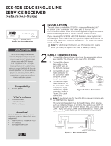
InstallatIon
Model SCS-1R Security Control Receiver
Description
The DMP SCS-1R Receiver ships from the factory with all of the necessary system components to provide two
Digital Dialer lines and one line of Data Network receiving capability. This package can be expanded to include
a maximum of ve incoming communication lines. The SCS-101 Network Interface Card allows you to connect a
digital data network to the SCS-1R Receiver.
SCS-1R Components Included
The SCS-1R includes the following:
• SCS-RACK with Modem and Multibus Racks, fan, and 32-Character LCD with Membrane Keypad
• SCS-1062 Processor Card
• SCS-100 Line Card (Two included)
• SCS-101 Network Line Card
• SCS-110 Modem Supply Card
• SCS-120 Multibus Power Supply Card
• SCS-130 Transformer Card
• SCS-202 Convenience Panel
• SCS-208 Power Cord

Digital Monitoring Products SCS-1R Installation Guide
6
InstallatIon
Model SCS-RACK System Enclosure
Description
The SCS-RACK houses the receiver processor, power supply, line cards, and associated cables. The enclosure
measures 8.75” high, 19” wide, and 12” deep.
Modem Rack
The SCS-RACK top portion holds the modem rack, which connects the SCS-110 Modem Power Supply Card and up
to ve line cards. The SCS-130 Transformer Card for connecting the 120 VAC mounts on the rear of the modem
rack.
Multibus Rack
The bottom portion of the SCS-RACK holds the Multibus Rack, which holds the SCS-1062 Processor Card and the
SCS-120 Multibus Power Supply Card.
32-Character LCD Membrane Keypad
Mounted on the front faceplate of the SCS-RACK is a 32-character LCD Membrane Keypad. The LCD and keypad
come pre-mounted and pre-wired with the power cable and ribbon cable.
Installing the SCS-RACK
Connect the SCS-RACK to earth ground before making any module connections. Use a minimum 14 gauge wire
for grounding. A crimp type spade connector is provided for connecting the ground wire to the ground lug on the
modem rack.
Rack Mounting
The SCS-1R must be mounted in a standard 19” rack for listed Fire Signaling applications. Simply slide the entire
unit into the 19” rack and secure with screws. Refer to the drawing below for rack-mounting hole locations.
SCS-RACK
System
Enclosure
Back
of
the
LCD
Keypad
built-in
to
the
Back of theLCD Keypad built-intothe
faceplate of the SCS-RACK
Knob used to lower
the faceplate of the
SCS-RACK
Knob used to lower
the faceplate of the
SCS-RACK
120 MultibusSCS-
e
r Supply Car
d
P
ow
e
1
06
2SCS-
e
ss
o
r C
a
r
d
P
r
o
c
e
SCS-100 Line Cards
SCS-101 Network
Line Card
Line
Card
Rack-Mountin
g
g
holes
SCS-110
Mod
em P
ow
w
er
Supply Ca
r
rd
Mu
lti
bu
s
R
a
c
k
e
m
Mode
k
R
a
c
k

SCS-1R Installation Guide Digital Monitoring Products
7
InstallatIon
Model SCS-1062 Processor Card
Description
The SCS-1062 is the main system processor that controls the line cards, the LCD display, and the printer. The SCS-
1062 contains the rmware for system operation, the operator code EEPROM memory, the line conguration, and
all time keeping functions.
Conguring the Port Jumpers
Before installing the SCS-1062 Processor Card, congure the
port jumpers for the desired communication type. The port
jumpers are the small gold jumpers located on each port,
as shown in Figure 1.
Ports 6, 7, and 8 are factory preset for proper operation
with the printer, LCD and keypad, and the host Computer
respectively. If you are setting a port for Network (NET)
communication, match the jumpers on the desired port
to the preset jumpers on port 6 for even number ports or
port 7 for odd numbered ports. Refer to the diagram below
when conguring the ports for NET or SDLC.
Conguring the Line Jumpers
After conguring the port jumpers, set the line
jumpers according to the positions listed in the
table below. The line jumpers are the small black
jumpers located on the back of each port as shown in
Figure 2.
For SDLC For NET
Line 1 1, 4, 6, 8 2, 3, 6, 8
Line 2
9, 11, 13, 16
9, 11, 14, 15
Line 3 17, 20, 22, 24 18, 19, 22, 24
Line 4 25, 27, 29, 32 25, 27, 30, 31
Line 5 33, 36, 38, 40 34, 35, 38, 40
Figure 2: SCS-1062 Line Jumpers
16
Jumper Settings
forLines 1and 2
1
2
3
4
5
6
7
8
9
10
11
12
13
14
15
Port 1
Port
2
Jumper Settings
forLines 3and 4
P
r
in
t
e
r
P
o
r
t
Jumper Settings
forLine5
32
17
18
19
20
21
22
23
24
25
26
27
28
29
30
31
33
34
35
36
37
38
39
40
Port
3Port5
Port 4
SCS-1062
NET NET
NET
Figure 1: SCS-1062 Port Jumpers
Z
Y
X
bb aa
dd cc
RQ
WTS
U
V
hh ii jj
PON
MLK
ED
J2
FJ
gg ff ee
J1
BA
Port 1
SDLC
Port 2
SDLC
C
Port 1
Port 2
Z
Y
X
bb
aa
dd cc
R
Q
WTS
U
V
hh ii jj
PON
MLK
ED
J2
FJ
gg ff ee
J1
BA
C
NET NET

Digital Monitoring Products SCS-1R Installation Guide
8
InstallatIon
Installing the SCS-1062
Always remove power to the SCS-1R Receiver when installing or removing the SCS-1062.
After setting the port jumpers and line jumpers, slide the SCS-1062 into the SCS-RACK lowest position, component
side up.
Install the SCS-202 Convenience Panel connectors on ports 6 and 8 and the line card at cables on ports 1 to 5.
Connect the ribbon cable from the keypad PCB to the SCS-110 Modem Power Supply card. Then connect the end
labeled with the number 7 to the SCS-1062 Processor Board port 7.
To SCS-1062 Port 7
To
SCS
-11
0
M
od
e
m
m
Power Suppl
y
Boa
r
rd
SCS-1062 LEDs
1) Far Left LED: Flashes constantly. This is the watchdog, or heartbeat, LED.
2) Center Left LED: On when the SCS-1R is saving data, such as programming changes.
3) Not used.
4) Far Right LED: On when memory resources are low, such as messages pending for host automation or the
printer.
Model SCS-100 Line Card
Description
The SCS-100 provides for one incoming line of digital dialer (DD) communication to DMP Command Processor™
panels. Each line card includes one 10-position at cable for processor card connection, and one RJ11X cable for
phone line connection from a customer supplied RJ11X connection block.
Transmit Level
The Transmit Level is the level of signal strength at which the SCS-100 transmits through the phone line. To adjust
the transmit level, place the 2-pin jumper on the desired level on the J11 Transmit Level header.
The Transmit Level comes from the factory set to -9 dB. -9 dB is the quietest, 0 dB is the loudest.
Echo Cancel Off
Echo Cancellation is technology used by telephone companies to stop echo from interfering with digital telephone
transmissions. In some cases this technology can interfere with alarm signals. If you have problems with Echo
Cancellation interfering with your signals, place the 2-pin jumper on the J12 Echo Cancel Off header to the
YES position to turn off the echo cancellers. If you are not having problems with the telephone company echo
cancellation, leave the jumper on the default setting of NO to leave the echo cancelers on.

SCS-1R Installation Guide Digital Monitoring Products
9
InstallatIon
Installing the SCS-100
Install the SCS-100 in any one of the SCS-RACK ve right hand positions with the card puller in the up
position. Connect the 10-position at cable between the line card and the processor card. The line
card line number is determined by the processor card port number.
PIN 1 OF THE FLAT CABLE CONNECTOR MUST BE IN THE SAME POSITION ON BOTH THE LINE CARD AND
THE PROCESSOR CARD.
-9 -6 -3 0
NO YES
Echo Cancel Off
J12
SCS-100
PWR
TD
RD
CD
OL
RG
DT
Phone Line Fail
Silence
RJ11X Phone
Line Input
Transmit Level
J11
Connecting the Phone Line
Install the RJ11X cable provided with the line card between the RJ11X connector on the line card front to a
customer supplied RJ jack. Use a standard 103J voice grade (analog) line. A slot is provided in the receiver back
plate for the RJ11X cable to pass through. Maximum line impedence is 100 Ohms. The phone line connection is
power limited and supervised for re communicating accounts.
The SCS-100 is registered with the FCC, registration number CCK8GW-16197-AL-N; Ringer Equivalence 1.2.
Phone Line Monitor
The SCS-100 monitors the incoming phone line voltage. During a loss of phone line voltage, the red Phone Line Fail
LED lights and the alert sounds. The alert can be silenced by pressing the silence switch on the SCS-100. The LED
remains lit until the phone line is restored.
Power Monitor LED
The green LED labeled PWR lights when the power supply on the line card is working properly.
SCS-100 LEDs
The six yellow LEDs indicate the line card condition during the various stages of communication. A description of
each LED is listed below:
TD Transmit Data On when the line card is transmitting to a panel.
RD Receive Data On when the line card is receiving data from a panel.
CD Carrier Detect On when the carrier tone from the panel is detected on the phone line.
OL On Line On when a digital dialer line card has answered the phone line.
RG Ring Detect On when ringing voltage is detected on phone line.
DT Data Terminal Ready On when the line card is ready to receive.

Digital Monitoring Products SCS-1R Installation Guide
10
InstallatIon
Model SCS-101 Network Interface Card
Description
The SCS-101 Network Interface Card provides for a connection from a digital data network to a port on the
SCS-1R Receiver. Each card includes one 10-position, 6-inch at cable for processor card connection, and one
eight-pin modular connector for digital data network connection. This allows the SCS-1R Receiver to accept alarm
and system messages over a network from DMP Command Processor panels. For optimum performance, install the
SCS-101 card in the SCS-1R Receiver line card slot 5. Refer to the SCS-101 Installation Guide (LT-0320).
SCS-101
Network Interface Card
TXD
RXD
RTS
CTS
DTR
TXC
RXC
Serial Input
Red Black
J8
TXD RXD
2
3
3
2
J3 J4J2
CLK
DCO
J5
FORCE
CTS
8-Pin Modular
Plug
Installing the SCS-101
Slide the SCS-101 into the modem rack line card slot 5 with the card puller in the up position, as shown in the
gures above. Connect the 10-position at cable between the SCS-101 Network Interface Card and the SCS-1062
Processor Card. Connect the IP network cable. Maximum line impedence is 100 Ohms. The network connection is
power limited and supervised for re communicating accounts.
Communication
The SCS-101 automatically communicates UDP or TCP with DMP XR500 Series and XR2500F Command Processor™
panels, iCOM-E™ Encrypted Network Alarm Routers, iCOM™ Network Alarm Routers, and iCOMSL Network Alarm
Communicators.
Important Compatibility Information
The SCS-101 line card Level E Version 200 or higher can ONLY be used with SCS-1R Receivers with rmware
Version 903 or higher and is NOT compatible with the SCS-1 Receiver.
The SCS-101 line card Level D Version 103 or lower can ONLY be used with the SCS-1R Version 902 or lower
or SCS-1 Receivers.
LED Indicators
The seven bi-color LEDs indicate the network interface card condition during various stages of communication.
A description of each LED is listed below:
TXD Transmit Data RXD Receive Data
RTS Ready To Send CTS Clear To Send
DTR Data Terminal Ready TXC *Transmit Clock
RXC *Receive Clock
* If the clock signal is present, both red and green segments of the LEDs light.
SCS-101 Data Jumper Settings
The SCS-101 data jumpers are pre-congured for NET at the factory.
RXD and TXD
The factory setting is Transmit Data (TXD) on pin #3 and Receive Data (RXD) on pin #2.
FORCE CTS
The jumpers are set vertically as the factory default. This allows the SCS-101 to tie the CTS and RTS data lines
together.

SCS-1R Installation Guide Digital Monitoring Products
11
InstallatIon
Model SCS-110 Modem Power Supply Card
Description
The SCS-110 provides power to a maximum of ve line cards. Power is supplied through the modem rack
backplane connectors without additional cabling. The SCS-110 also provides LCD and keypad connection, UPS
system status, and the 120 VAC input monitoring information to the SCS-1R Receiver.
Installing the SCS-110
Always remove power to the SCS-1R Receiver when installing or removing the SCS-110.
Slide the SCS-110 into the modem rack far left hand position, with the card puller up as shown below.
Plug the at cable from the membrane keypad PCB onto the card edge connector at the bottom of the
SCS-110.
Power Monitor LEDs
The green LED labeled PWR lights when the power supply to the SCS-110 is working properly. The red LED labeled
PWR TRBL is controlled by the SCS-120 Multibus Power Supply Card and lights when there is a power problem on
the SCS-110. The red LED remains lit until the power problem is corrected. The alert tone on the SCS-110 Modem
Power Supply Card sounds during a power problem and is silenced by pressing the silence switch on the SCS-110.
LCD Membrane Keypad Trouble LED
The LCD Membrane Keypad trouble LED lights and the alert tone sounds when the LCD Membrane Keypad fails to
operate or the cable is unplugged. The alert tone is silenced by pressing the silence button on the SCS-110.
UPS Trouble LED
The UPS (Uninterrupted Power Supply) trouble LED lights and the alert tone sounds when the UPS Brownout Input
is opened. Connect this circuit to the brownout contacts on your UPS system (Refer to SCS-130 information). No
End-of-Line resistor is needed. Silence the alert tone by pressing the silence button on the SCS-110.
AC Trouble LED
The AC trouble LED lights and the alert tone sounds when AC power to the SCS-130 Transformer Card fails. Silence
the alert tone by pressing the silence button on the SCS-110.

Digital Monitoring Products SCS-1R Installation Guide
12
InstallatIon
Model SCS-120 Multibus Power Supply Card
Description
The SCS-120 provides power to the SCS-1062 Processor Card through the multibus backplane. The SCS-120 also
monitors the SCS-1062 Processor Card condition, the SCS-110 Modem Power Supply Card voltage output, and its
own internal voltages.
Installing the SCS-120
Always disconnect power to the SCS-1R Receiver when installing or removing the SCS-120. Slide the
SCS-120 Multibus Power Supply Card, the component side up, into the multibus rack upper position,
which is the lower rack in the SCS-RACK.
Connect the SCS-208 Power Cable to J3 on the card front right side. Connect the other end of the
power cable to the SCS-130 Transformer Card on the back of the modem rack. The power cable can be
used in either direction.
Processor Monitor
The SCS-120 monitors the Model SCS-1062 processor through the multibus backplane. The green OK LED lights
when the processor operates. If the processor stops operating, the red FAIL LED lights and the SCS-120 failure
buzzer sounds.
Press the processor restart button to restart the system, silence the buzzer, and turn off the red LED. The restart
button restarts the system and resets the time of day. All other system conguration information is not changed.
Power Monitor LEDs
The SCS-120 monitors three different system voltages, +5, +12, -12 and the modem power supply. Four LEDs
located to the right of the power alert silence switch display any voltage failures. A green OK LED lights when the
voltages are working properly. The green PWR LED for the modem power supply is located on the SCS-110 Modem
Power Supply Card. The red TRBL LED lights and the trouble alert tone on the SCS-120 sounds when there is a
problem with a voltage level.
Press the SCS-120 power alert silence switch to silence the alert tone. The red TRBL LED remains lit until the
power problem is corrected. The modem power LED, the SCS-120 trouble alert tone, and the SCS-110 Modem
Power Supply Card power alert LED all operate together.

SCS-1R Installation Guide Digital Monitoring Products
13
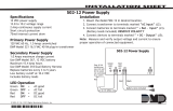
InstallatIon
Model SCS-130 Transformer Card
Description
The SCS-130 provides power to the SCS-110 Modem Power Supply Card and the SCS-120 Multibus Power Supply
Card. Two terminals are provided for connecting 120 VAC to the system. A power cord is provided for connecting
the multibus rack cooling fan.
3 Amp 250V
To fan
COM
J3
J2
HOT
AC Power Cord
Installation
Always remove power to the SCS-1R Receiver when installing or removing the SCS-130.
1. Install the SCS-130 with J2 on the right side on the rear of the modem rack and J3 on the bottom
as shown above. Four 6-32 screws with lock washers are provided.
2. Connect the SCS-208 Power Cable to J3 on the bottom left of the SCS-130 Transformer Card.
Connect the other end of the power cable to the SCS-120 Multibus Power Supply. The power cable
can be used in either direction.
3. Connect the cable from the right end of the modem rack labeled J2 to J2 on the right side of the
SCS-130 Transformer Card.
4. Connect the 2-conductor cables labeled TO FAN to the multibus cooling fan on the lower right side
of multibus rack.
AC Power Connection
Connect 120 VAC to the SCS-1R Receiver through the SCS-130 Transformer Card. The SCS-1R Receiver backplate
provides a 7/8” conduit opening.
1. Wrap the supplied lay-in strain relief around the AC power cord approximately 18 inches from the end of the
wires.
2. Feed the end of the AC power cord through the conduit opening until the strain relief snaps into the opening.
If necessary, use pliers to compress the strain relief until it snaps into the opening.
3. Connect the White AC power cord wire to the COM terminal on the bottom of the SCS-130.
4. Connect the Black AC power cord wire to the HOT terminal on the bottom of the SCS-130.
5. Connect the Green AC power cord ground wire to the grounding lug located on the right side of the enclosure.
The AC power must be provided by a listed UPS. A signal shall be provided at the operators console when the UPS
power source switches from primary power to secondary power.
DO NOT APPLY POWER TO THE RECEIVER UNTIL THE REAR COVER IS REPLACED ON THE RECEIVER CABINET.
Three Amp Fuse
The 120 VAC connection to the SCS-1R Receiver is current limited with a DMP Model 319, 3 Amp 250 volt fuse. The
3 Amp fuse is a Type AGC 1/4” x 1 1/4” fast blow.

Digital Monitoring Products SCS-1R Installation Guide
14
InstallatIon
Model SCS-208 Power Cable
Description
The SCS-208 is a 2-foot cable that connects the different system voltages between the SCS-130 Transformer Card
J3 and SCS-120 Multibus Power Supply Card J3.
Installation
The SCS-208 cable can be used in either direction, but is polarized on each end for proper installation to the J3
connectors.
Model SCS-202 Convenience Panel
Description
The SCS-202 provides cabling for two supervised, power limited RS-232 ports for the host output and an activity
log printer.
Installation
Install the two 10-position at cable connectors to the SCS-1062 Processor Card ports 6 and 8. Connect the ribbon
cable between port 6 and the Activity Log printer connector. Connect the other ribbon cable between port 8 and
the Host Computer connector. Install the metal plate with the two 25-position RS-232 connectors on the SCS-1R
Receiver backplate using the two 6-32 x 1/4” screws provided. Connect the printer using a DMP Model 389 Printer
Cable and host computer to the appropriate RS-232 connectors.
Model SCS-204 Host Cable
Description
The SCS-204 is a 10-foot RS-232 cable that connects a host computer to the SCS-1R Receiver.
Installation
Connect the SCS-204 cable from a host computer to the SCS-202 Convenience Panel center connector marked
“HOST”.
THE END OF THE CABLE MARKED “HOST” MUST BE INSTALLED ONTO THE HOST COMPUTER.
Host Cable
If you are using a cable different from the SCS-204, be sure the cable pin out matches the drawing below. RS-232
maximum cable length is 50 feet.
PIN
SHIELD
1
2 RXD
3 TXD
4
5
7
8
SIGNAL GROUND
MALE
DB-25
DB-25
(DB-9)
2 (3)
3 (2)
7 (5)
Connect to
HOST
COMPUTER
(DTE)

SCS-1R Installation Guide Digital Monitoring Products
15
OperatOr’s Guide
SCS-1R Printer Cable
Printer Cable Pinout
Note: UL central station applications must use a serial printer that is listed for Fire Protective Signaling Systems.
Shown is an example printer cable pin out. Some printers use DB9 connectors and may use pin 20 for CTS. The
printer RS-232 is supervised, power limited, and the maximum cable length is 50 feet.
To
Printer
Security Control Terms
This is an alphabetical list of terms used in the SCS-1R Receiver system operating instructions. Refer to these
explanations for additional information.
ACK - Acknowledge an alarm signal by pressing any top row Select key on the Membrane Keypad.
Alphanumeric - A set of characters consisting of either the letters A through Z, the digits 0 through 9, special
symbols, or a combination of all of these. For example, the set of characters “AB76#2,” is alphanumeric.
Character - One of a set of symbols that can be arranged in groups to express information. This includes the digits
0 through 9, the letters A through Z, punctuation marks, and other special symbols.
Command Processor Programs - The data programmed into a DMP Command Processor™ panel at the time of
installation. A typical program includes: communication information, system options, area information,
Programs zone information, and the number and type of Security Command® keypads in the system. This
should not be confused with System Programs that are software routines used by the SCS-1R to execute
functions described in the Operations Manual.
COMMAND - The key on the Membrane Keypad used to scroll through programming and enter programming
information.
LCD Membrane Keypad - A 32-character Liquid Character Display that displays information and provides a
Membrane Keypad that allows you to enter information.
Default Value - A value assigned to a prompt by the SCS-1R. The SCS-1R Receiver assigns the value to that prompt
allowing the operator to accept its entry and respond to the next prompt.
Entry - Information typed into the SCS-1R through the LCD Membrane Keypad mounted in the front of the
SCS-1R. This information is entered into the system when the COMMAND key is pressed.
Prompt- A single item of information on the LCD. For example, a prompt within the System Conguration program
would be the company name.
Menu - An LCD display that lists the program selections available to the operator.
Numeric - Description of numerical information. For example, the set of characters 1 2 3 4 5 is numeric.
User Number - The sequential number assigned to each user code number by the panel during its programming.
This is the number transmitted to the SCS-1R Receiver. The actual code number is never transmitted.
/