Page is loading ...

Cover
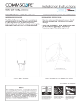
Radome
Eye Bolt
Cover
Figure 2. Hinged Covers
Figure 1. 3X-C70B-3XR
Covers
Thumb Screws
Base Plate
Thumb Screws
INSTALLATION INSTRUCTIONS
Micro AcCELLerator Antennas
CommScope Infrastructure Academy offers installation training.
Bulletin 628043 • Revision A • March 2015 Page 1 of 4
Installation Instructions
TM
3X-C70B-3XR
GENERAL INFORMATION
covers.
DO NOT remove the EYE BOLT after installation, otherwise
water ingress to antenna may occur.
The 3X-C70B-3XR antenna (Figure 1) is a compact, tri-sector
antenna solution equipped with two hinged covers at the
base of the antennas which enable access to the RF and
AISG ports plus the mounting interface. Since mounting
locations and surfaces will vary, CommScope does not
provide the mounting bolts or associated hardware required
to properly install this antenna. It is the responsibility of
qualified personnel to determine the best method for
securely anchoring the base plate of the antenna to the
mounting surface.
After removing the antenna from its shipping container
carefully inspect it to ensure there is no shipping damage. If
the antenna is to be hoisted into position, ensure the lifting
eye bolt is correctly installed. Ensure the antenna is securely
held during hoisting to avoid rotation on the lifting eye bolt.
1. Loosen the thumb screws (Figure 2), and open the
(continued on page 2)

3X 120.0°
228.60
(Continued from page 1)
CommScope
Bulletin 628043 • Revision A • March 2015 Page 2 of 4
3X-V65A-3XR Antenna
Figure 3. Mounting and Cable Routing Holes on Base.
(continued on page 3)
to securely anchor the antenna.
prior to installing the antenna.
be marked and made ready in the mounting surface
alignment. It is recommended that the mounting holes
2. Refer to Figures 3, 4 and 5 for mounting and boresite
desired performance.
antenna must be considered prior to mounting to ensure
indicator (featured in Figure 5). The direction of each
The boresite of each antenna is shown by the boresite
3. Using customer supplied hardware, mount the base plate
of the antenna to the mounting surface. Tighten hardware
Viewed From Bottom Side Of Antenna
BASE PLATE
8 mm THICK
Recommended hardware is M16 or 5/8"
3X 40.20
75.00
3X 106.07
3X R76.20
6X R23.21
283.50
3X 17.5
Mounting Holes
Equi-Spaced in 3 Positions on 228.6 mm PCD

Boresite
Indicator
(Continued from page 2)
RET CABLE
5. Attach the RF cables to the antenna input connectors and
torque to 25-30 Nm (Figure 5).
RF CABLE
(X6)
CommScope
Figure 5. Routing Cables.
(continued on page 4)
provides openings that can be used to route cable through
to enhance noise and lightning immunity. The antenna base
Route RF cable along metal rails, etc. as much as possible,
the AISG connection in the antenna. If needed or
Bulletin 628043 • Revision A • March 2015 Page 3 of 4
waterproofing) to the mating connectors (Figure 4).
required by local procedures apply mastic (or similar
Figure 4. Connector Interface.
the base when mounting on a monopole (Figure 3).
exceed 1.1 Nm. Using excessive torque may damage
Female
AISG 8 Pin DIN
4. Remote Electrical Tilt Connection.
A single AISG 8 Pin DIN Male input connector interface
is provided which will accept a cable assembly
terminated with a standard AISG compliant 8 Pin DIN
Female connector. An AISG 8 Pin DIN Female output
connector interface is also provided which enables a
“daisy” chain connection to other AISG compliant
devices should it be required. After ensuring the
connector is dry, push in the mating connector. Tighten
the AISG mating connector by hand only. Do not apply
any more rotational force to the AISG mating connector
than needed to properly mate the seal and do not
AISG 8 Pin DIN
Male
Don't remove female AISG connector cap if it is not used.

Notice: CommScope disclaims any liability or responsibility for the results of improper or unsafe installation, inspection, maintenance, or removal practices.
Aviso: CommScope no acepta ninguna obligación ni responsabilidad como resultado de prácticas incorrectas o peligrosas de instalación, inspección, mantenimiento o retiro.
Avis : CommScope décline toute responsabilité pour les conséquences de procédures d’installation, d’inspection, d’entretien ou de retrait incorrectes ou dangereuses.
Hinweis: CommScope lehnt jede Haftung oder Verantwortung für Schäden ab, die aufgrund unsachgemäßer Installation, Überprüfung, Wartung oder Demontage auftreten.
Atenção: A CommScope abdica do direito de toda responsabilidade pelos resultados de práticas inadequadas e sem segurança de instalação, inspeção, manutenção ou remoção.
Avvertenza: CommScope declina eventuali responsabilità derivanti dell’esecuzione di procedure di installazione, ispezione, manutenzione e smontaggio improprie o poco sicure.
注意:CommScope 公司申明对于不恰当或不安全的安装、检验、维修或拆卸操作所导致的后果不负任何义务和责任。
@2015 CommScope Bulletin 628043
Customer Service 24 hours
North America: +1-800-255-1479 (toll free)
Any country: +1-779-435-6500
email: acicustomersupportcenter@commscope.com
CommScope
1100 CommScope Place SE P.O. Box 339, Hickory, NC 28603-0339
(828) 324-2200 (800) 982-1708
www.commscope.com
(Continued from page 3)
Thumb Screws
CommScope
Do not install on a wet or windy
results of improper or unsafe installation practices.
Figure 7. Tighten the screws
day or when lightning or thunder
ladder.
is in the area. Do not use metal
applicable safety precautions as shown on this page.
when the field installation is performed. Follow all
It is recommended that transmit power be turned off
Figure 6. Covers with attached screws
6.
Figure 7.
Once the antenna is correctly installed and positioned, all
RF cables, RET cables and securing hardwares are correctly
tightened, the covers should be re-attached.
Do not install near power
CommScope disclaims any liability or responsibility for the
When attaching the covers, make sure the screws are
attached to the covers (Figure 6), then install the thumb
screws to the holes, tighten the screws by hand. see
Bulletin 628043 • Revision A • March 2015 Page 4 of 4
Wear shoes with rubber soles
and heels. Wear protective
clothing including a long-
sleeved shirt and rubber
lines. Power lines, telephone
lines, and guy wires look the
gloves.
same. Assume any wire or
line can lectrocute you.
SAFETY NOTICE
The installation, maintenance, or removal of an antenna
requires qualified, experienced personnel. CommScope
installation instructions are written for such installation
personnel. Antenna systems should be inspected once a
year by qualified personnel to verify proper installation,
maintenance, and condition of equipment.
Covers
/