LY International Electronics M-1116 Owner's manual
- Type
- Owner's manual

Public Address System
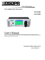
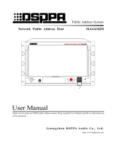
Micro Intelligent Host
M1116/M1116D
PLAY
EMC REC
FULL
ALRMRMING
USB
MP3
INTELLIGENT PUBLIC
ADDRESS CENTRE M1116
Operation Instructions
Welcome to use our public address system. For the better application of this equipment, please read the
operation instruction carefully prior to use.
LY I n t e r n a t i o n a l E l e c t ro n i c s C o . , L t d .
www.lyintlcorp.com

About this Manual
This manual contains the micro-intelligent M1116 / M1116D equipment system
introduction, the use of precautions, system connection instructions, product use
instructions and many other contents. Please read this manual carefully before connecting
and installing. And follow the instructions in the instructions to operate.
A description of this logo on the rear panel of the equipment is a matter that must be noted.Be sure to
use or follow these instructions when using it

Warning
This symbol indicates "forbidden content" This symbol indicates "compulsory content
■ Please make sure that the
power wire is NOT damaged.
Do NOT unplug the equipment
by pulling the power wire;
otherwise it may cause electric
shock, short circuit or fire.
■ When the equipment is in use, DO NOT block the air
outlet which should be kept clear, in order to avoid
overheat.
■Do NOT store this
equipment in any
place with heavy
dust or vibration, or
where it is extremely
cold or hot.
■ Please do NOT place any heavy article on this
equipment. Please operate
switches, buttons or
external audio source
carefully.
■ Please prevent foreign matters (such as paper,
metal etc.) entering the equipment through the gaps
or opening, in such cases, please cut off the power
supply
immediat
ely.
■ Do NOT attempt to remove any internal component
from the equipment, or to
modify the equipment in
whatever manner.
■ In case that sound is suddenly off or there is
abnormal odor or smoke, please unplug the
equipment from the power socket to avoid potential
electric shock, fire or other accident. The equipment
should be inspected by professional personnel.
Burning Smell
■ If the equipment is not in use for a long period, please
unplug it from the AC power socket to realize zero
energy consumption.

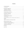
Contents
I. Product Description...................... ...............................................................................1
1.1 Specification...............................................................................................................1
II. Description of Appearance........................................................................................2
2.1Introduction to Front Panel..........................................................................................2
2.2Introduction to Rear panel...........................................................................................3
III. Instructions to Connection......................................................................................4
3.1Schematic diagram of connection................................................................................4
IV. Instructions to Operation ........................................................................................4
4.1Description of main interface.......................................................................................5
4.2Setting of system..........................................................................................................7
V. Description of Other Functions.................................................................................20
5.1Priority ranking...........................................................................................................20
5.2Priority and operation relation of emergency business sound source.........................20
Appendix.........................................................................................................................21
Application Instructions to File Format of USB:.........................................................21
Operations for Remote Control ....................................................................................22
1. Operations for use of remote control...........................................................................22
2. Operations for timing point edition interface..............................................................22
3. Operation for peripheral control..................................................................................23
4. Operation for system setting........................................................................................25
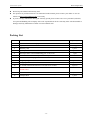
Packing List ....................................................................................................................28
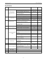
Specification....................................................................................................................29

Public Address System Micro Intelligent Host
- 1 -
I. Product Description
1.1 Specification
Power supply at 220V and 24V (Only available for M1116D);
5.0” resistance LCD touch screen, optional interface in Chinese and English, and built-in 1G memory;
One channel of fire alarm switch and emergency microphone. The emergency microphone is used for
emergency paging and business paging. In case of the emergency paging, it is possible to take up the
emergency microphone for paging after the emergency triggering; in case of the business paging, it is
possible to take up the emergency microphone for paging after selecting one or more partitions on the local
interface;
One audio playback button, which is used to play the emergency audio recording; the audio shall be recorded
with the MIC or LINE port on the panel. For the emergency audio recording, the audio shall be recorded in
the format of MP2 with the duration for 10 minutes;
Background sound source recording. The audio shall be recorded with the MIC or LINE port on the panel.
When configuring the factory songs, it is possible to record the audio for 4 hours;
USB interface: The configured content (Including songs or timing points) may be imported from USB into
this equipment; the configured content may also be exported from this equipment to USB. It is also possible
to use USB to upgrade the latest software through USB, or to play the music programs in USB, but only the
songs in the MP3 audio format can be played;
Level indicator: It is used to indicate the outputs of all the signal sources;
RJ45 interface (Connected to PC computer online to download and update the songs at any time, and to
download the edition timing point on a remote basis);
4 channels of timing power time sequencer (Maximum gross power of 220V/2000W) and 1 channel of short
circuit triggering interface (Trigger control time sequencer);
2 channels of paging microphone interface (Connected to PB9810R), 1 channel of background and 1 channel
of emergency (Paging) line output, and 1 channel of wireless microphone input;
10 channels of short circuit triggering. The alarm sound source is generated from this equipment. The alarm
level may be a high level (+5V---+24V) or low level (0V);
It is possible to connect 5 background power amplifiers (Maximum power 2000W) and 1 emergency (Paging)
power amplifier (Maximum power is 2000W). 10 channels of partitions are built in (Maximum gross power
is 2000W, average maximum power of each partition is 200W; every power amplifier corresponds to 2
channels of partitions. That is to say that the first channel of the power amplifier corresponds to partition
No.1 and partition No.2; the second channel of the power amplifier corresponds to partition No.3 and
partition No.4, and so on);
It is equipped with 4Ω /10W (1kHz, 1% degree of distortion) monitoring output.
It is possible to edit 5 sets of timing programs (Timing in periodic cycle and timing at designated date). In
each set of the program, it is possible to edit 200 timing points at most. The content of each timing point shall
include the build-in power supply (Only on or off state), partition (Only on or off state), MP3 sound source

Public Address System Micro Intelligent Host
- 2 -
(20 songs at most); the timing point may set the end time;
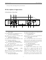
II. Description of Appearance
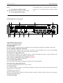
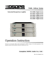
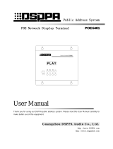
2.1 Introduction to Front Panel
PLAY
EMC REC
FULL
ALRMRMING
USB
MP3
1 2 3 4 5 6 7 8
910111213
1. Power switch
Press down the position “T” to indicate the switch-on.
2. Line mode recording interface
The interface used to record the background sound
source or emergency sound source.
3. MIC mode recording interface
The interface used to record the background sound
source or emergency sound source.
4. Recording volume adjustment knob
Adjust the size of the volume in a mechanical manner.
5. 5.0” LCD touch screen
The display screen is used to display all the
information and trends of the system. It is also used as
the operation touch screen.
6. Emergency microphone volume
adjustment knob
When the arrow of the knob is turned to MIN, it
indicates the minimum volume; when turned to MAX,
it indicates the maximum volume.
7. Emergency microphone port
The signal of the microphone to be connected to this
port shall have the highest priority.
8. Microphone hook
If the microphone is not in service, put the button on
the back of the microphone into this hole.
9. Alarm button
This is the system alarm button. Press down this
button to send the alarm signal to all the partitions
simultaneously; Press down this button again to shut
down the alarm and bounce the button up.
10. Audio playback button
It is used to play the emergency audio recording.
11. USB interface
The configured content (Including songs or timing
points) may be imported from USB into this
equipment; the configured content may also be
exported from this equipment to USB. It is also
possible to use USB to upgrade the latest software
through USB, or to play the music programs in USB,
but only the songs in the MP3 audio format can be

Public Address System Micro Intelligent Host
2
played.
12. Out signal level indicator lamp
The indicator lamp for all the signal source outputs.
13. Power supply indicator lamp
The indicator lamp is on when the power supply is
turned on, or is off when the power supply is turned
off.
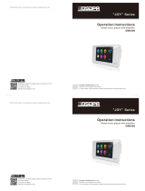
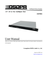
2.2 Introduction to rear panel
LINE A OUT
BACKGROUND BROADCAST
EMERGENCY BROADCAST &
BUSINESS ANNOUNCEMENT
LINE B OUT
~220V/2KW POWER OUT
CH 3 CH 4CH 2CH 1
RISK OF ELECTRIC SHOCK
DO NOT OPEN
CAUTION!
请勿打开,以免触电
警告
LAN ALARM INPUT
WL
MIC IN
DATA SHORT
OUT
1. Data interface (Not in service)
2. Short circuit output interface
It is used to output the low level
3. Partition input
It is used to connect 5 background power amplifiers and one emergency (paging) power amplifier respectively.
4. Power amplifier loudspeaker output port
The partition output terminals CH1 to CH10 are connected to the loudspeaker boxes in the corresponding
partitions respectively in order for the direct output of the audio signal.
5. AC220V power supply input socket
The working power supply to this equipment shall be connected through this interface; when connecting, first
insert the socket on this equipment, and then connect the grid.
6. DC 24V power supply input (Only available for M1116D)
DC 24V backup power supply input interface.
7. Power supply output interface
It is used to provide the AC220V working power supply to the other equipment.
8. Partition alarm signal input interface
It is used to input the signal from the fire service center.
9. Network interface
It is connected with PC computer to download and update the songs at any time and to download and edit the
timing points on a remote basis.
10. Remote pager connector
There are two remote pager connectors (9-pin D-type data serial port), which are used to connect the remote pager
equipment (PB9810R) directly.
11. Monitoring output
6
7
8
9
10
11
12
13
1
2
3
4
5
14

Public Address System Micro Intelligent Host
- 3 -
The maximum output power is 4Ω /10W (1kHz, 1% degree of distortion)
12. Line B channel output interface
The emergency business sound source output interface.
13. Line A channel output interface
MP3 sound source output interface.
14. Wireless microphone input interface
It is used to input the signal generated by the wireless microphone. If the signal is not big enough, it is required to
equip the pre-amplifier to connect to this interface.
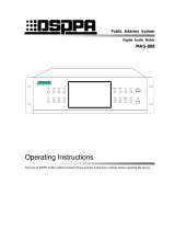
III. Instructions to Connection
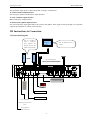
3.1Connection diagram
LINE A OUT
BACKGROUND BROAD CAST
EMERGENC Y BROADCAST &
BUSINESS ANNOU NCEMENT
LINE B OUT
~220V/2KW POWER OUT
CH 3 CH 4CH 2CH 1
RISK OF EL ECTRIC SHOCK
DO NOT OPEN
CAUTION!
请勿打开,以免触电
警告
LAN ALARM INPUT
WL
MIC IN
DATA SH ORT
O UT
Fire service center
PC
Remote pager 1
Remote pager 2
Amplifier 5
Power amplifier A
(MP3 sound source)
Power amplifier B
(Emergency business sound
source)
Amplifier 1
Note: It is possible to
connect 5 background
power amplifiers with
maximum power of each
amplifier less than 400W
Emergency
Amplifier
Note: The Maximum power is
2000W
CH1—CH10 partitions

Public Address System Micro Intelligent Host
- 4 -
IV. Instructions to Operation
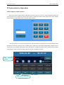
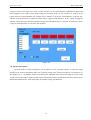
4.1Description of main interface
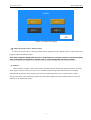
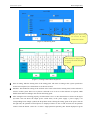
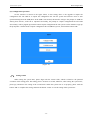
Turn on the power supply and the equipment will start to boot. In such case, if the equipment enables the
system password, it is required to enter the password for verification as shown in the figure below. After entering
the password, press the button “OK” to enter the main interface.
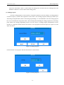
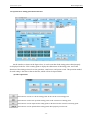
The main interface is shown in the figure below. The information to be displayed on the main interface shall
include the current time and date, state of timing point, sound source operation including MP3 program, state of
10 partitions, power supply output control state and operation, setting of program control / manual control, setting
of monitoring, setting of business paging, operation options, and other operations.
Main Interface
Program control / manual control
MP3 operation
interface

Public Address System Micro Intelligent Host
- 5 -
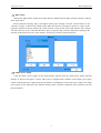
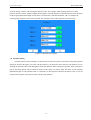
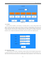
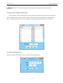
(1)MP3 control
Clicking the “MP3 control” button on the main interface and then enter the MP3 operation interface as shown
in the figure below:
For the operation of playing, firstly, selecting the directory (For example, select the “classical music”) in the
“directory of songs” on the left side, and the tracks under such directory will appear in the list of “songs” on the
right side, and then set the play mode in the “mode selection” on the top left corner of the interface (For example,
select the “directory cycle”), and click the button “play” to play the songs, which are displayed as playing in the
state bar on the bottom left corner of the interface, and click it to return to the main interface.
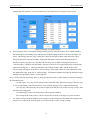
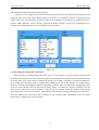
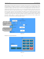
(2)Output power supply
Click the button “power supply” on the main interface and then enter the output power supply operation
interface as shown in the figure (1) below. This system is equipped with 4 channels of the output power supply
control. Clicking the power supply button directly,which is controlling the on/off of the power supply. The output
power supply is also subjected to the automatic timing control. Upon the completion of the operation, just click
the return button.

Public Address System Micro Intelligent Host
- 6 -
(Figure 1) Output Power Supply
(3)Shift of program control / manual control
As shown in the figure above, directly click the button “program control / manual control” to shift between the
program control and manual control.
Note: After setting the timing point, be sure to set this button as “program control” to execute the timing
point; If such button is displayed as “manual control”, all the timing points will not be executed.
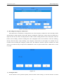
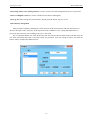
(4) Monitor
Click the button “monitor” on the main interface and then enter the monitoring operation interface as shown
in the figure (2) below. In this system, there are two kinds of monitoring sound source modes for switching
(Background sound source and emergency & business broadcasting sound source). On this interface, please
directly click either of the monitoring sound sources (the button displayed in green indicates that it is selected),
and then set the monitoring volume.

Public Address System Micro Intelligent Host
- 7 -
(Figure 2) Setting of Monitoring
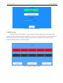
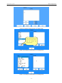
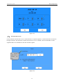
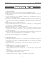
(5) Business paging
Click the button “business paging” on the main interface which is popping up the following operation
interface, and press down the partition to be paged. It is allowed to press down the button “select all partitions” or
directly click the partition to be paged for paging, and the button of such partition will be displayed in red
(Indicating that this partition is selected and paged).
(Figure 3) Setting of Business Paging

Public Address System Micro Intelligent Host
- 8 -
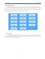
4.2 Setting of system
On the main interface, click the button “operation option” to enter the system setting interface as shown in
the figure (4) below. On the system setting interface, it is allowed to set the overall information of the system.
Prior to the playing and other actions on the main interface, all the items shall be set properly in the system setting,
so that all the functions of the system will execute and operate accurately.
(Figure 4) Operation Options
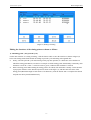
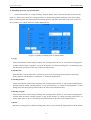
(1) Setting of timing
On the interface of operation options, click the “setting of timing” to enter the interface as shown in the
figure (5) below. On this interface, there are the timing points, which have been edited properly, and the
information on the functions of the timing points.

Public Address System Micro Intelligent Host
- 9 -
(Figure 5) Setting of Timing
Editing the functions of the timing point are shown as follows:
1) Add timing point : (For periodic cycle)
On the main interface of “setting of timing”, click the button “add” to enter the interface as shown in figure (6)
below. The timing modes shall include the timing in periodic cycle and timing at designated date.
① Firstly, select the periodic cycle and selecting weekly. By this operation, it is allowed to select the date on
which the timing point shall be executed. For example: If all the timing points from Sunday to Saturday, click
the button “select all”; if the“√” in the box turns to green, it indicates that such date is selected.
② Name of timing point: When naming the timing point to be edited, click the button “modify” on the interface
to pop up the interface of the edition keyboard as shown in the figure (7), and then enter the name of the
timing point (Maximum length of such name is 30 characters), click the button “OK” to complete the edition
and push out the keyboard simultaneously.

Public Address System Micro Intelligent Host
- 10 -
(Figure 6) Add Timing Point
(Figure 7) Timing Point Edition Keyboard
③ Time of timing: Edit the starting time of the timing point. The time of timing in this system specified to
second. If not required, it is allowed not to set the time second.
④ End time: The method for setting of the end time is the same as that for the starting time, but the end time is
selective in this system. That is to say that it is allowed to set or not to set the end time as required, which
shall be determined according to the need for the timing point.
⑤ After setting the time of timing properly, click the button “next” to enter the interface as shown in the figure
(8) below. The left shows the output power switch status, in the power supply 1 power supply 4 its
corresponding lower triangle symbol, the drop-down menu selecting the timing point in the power state.On
the right side, the partition control options are displayed. There are the on and off states for the partition
control. Click the button “select all” or select a single partition separately (The button displayed in green
Please selecting the language before
the entering. The Chinese and English
are optional.
Selecting here before setting
the end time; the ticking
indicates that it is selected.

Public Address System Micro Intelligent Host
- 11 -
indicates that this partition is selected), and then select the control state as required (Click to select).
(Figure 8) Setting of Timing Partition
⑥ Select program: After selecting the timing partition properly, select the button “next”,which is adding
the sound source to the timing point, and enter the program setting interface as shown in the figure (9)
below. The timing point may carry out the play control on the built-in MP3 at the same time; when
setting the program of the built-in MP3, firstly,click the button “add” to enter the built-in player
interface as shown in figure (10), and select the directory (For example, selecting the directory of
“classical oldies”, and then click the button “directory at next level” to open the directory and select the
tracks therein (Figure 11). After selecting the tracks, click the button “add”, and the names of the
selected songs will appear in the list of “selected songs” in the right column. It is also allowed to delete
the undesirable songs in the list of “selected songs”. The deletion method: Selecting the undesired songs,
and then click the button “delete” on the right side.
In case of the operation of playing, there are three optional play modes, which shall be selected according to
the individual needs:
(1) Order play: The songs will be played in the sequential order. When the playing of the last song
is over,and the timing of the set time has not yet arrived,the playing will be stopped automatically.
(2) Loop play: When playing, the system will play from the first song to the last song on loop, until
the end of the timing point.
(3) Random play: The tracks in the player will be played at random.
After setting all the items properly, return to the interface as shown in the figure (9) below, and click
the ”finish” button to finish the addition of the timing point. The timing point that added will be displayed in
the list box of “edit content of timing point” on the main interface of the “setting of timing”.

Public Address System Micro Intelligent Host
- 12 -
(Figure 9) Setting of Sound Source of Timing Point
(Figure 10) Setting of Sound Source of Timing Point
(Figure 11) Setting of Sound Source of Timing Point
After selecting the directory in
the box above, clicking here to
open the directory and
selecting the tracks.

Public Address System Micro Intelligent Host
- 13 -
2) Add timing operation: (by specified time)
On the main interface of “setting of timing”, click the button “add” to enter the interface as shown in the
figure (13) below. Select the type of “designated time” to edit the timing mode, modify the name of the timing
point, set the designated date, starting time and end time properly. The other operations are the same as those of
the “periodic cycle”, which will not be further elaborated here.
(Figure 13) Setting of Timing Time of Timing Point
3) Copy
On the main interface of the setting of timing, click a timing point in the list of “edit content of timing point”,
and then click the button “reproduce” to pop up the interface of “setting of timing time” of such timing point;
the subsequent operations are the same as those introduced above.
4) Modify time
When the time is not satisfied with a certain time point, select such timing point in the list of the timing
points, and then click the button “modify time” to enable the modification.
5) Modify partition
On the main interface of the setting of timing, click a timing point in the list of “edit content of timing point”,
and then click the button “modify partition” to pop up the interface of “setting of timing partition” of such
timing point. The subsequent operation mode is the same as that introduced above.
6) Modify program
On the main interface of the setting of timing, click a timing point in the list of “edit content of timing point”,
and then click the button “modify program” to pup up the interface of “setting of timing sound source” as
shown in the figure (9) above. The subsequent operation mode is the same as that introduced above.
7) Delete
Deletion of timing point: To delete the timing point, there are two buttons for single deletion and all deletion

Public Address System Micro Intelligent Host
- 14 -
respectively. The button “delete” is used to delete the timing points selected in the list of timing points, and
the button “delete all” is used to delete all the timing points.
(2) Timing program
Click the “timing program” on the interface of operation options to enter the interface of timing program
as shown in figure (14) below. This equipment is able to edit 5 sets of timing programs (Timing in periodic cycle
and timing at designated date); Prior to the timing programming, it is recommended to select the timing program
here so as to facilitate the using in the future. After selecting and confirming the timing program here, the timing
point edited in the timing programming will be saved in such set of timing program automatically. On this
interface, it is allowed to rename and save the current 5 sets of programs as shown in figure (14), figure (15), and
figure (16) below.
(Figure 14) Timing Program
Click the button “save program” and enter the interface as shown below:
(Figure 15) Saving Program

Public Address System Micro Intelligent Host
- 15 -
Click the button “rename” and entering the interface below. For example, when renaming the first set of the
program, click the button “modify” behind such program to enter the interface of edition keyboard, enter the name
of the program (Maximum length of such name is 30 characters), and click the button “OK” to complete the
renaming of the program, and exit the keyboard. The operations of the other programs are just the same.
(Figure 16) Renaming of Program
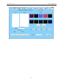
(3) Partition naming
Click the button “partition naming” on the interface of operation options to enter the setting of the partition
naming as shown in the figure (17) below. On this interface, it is allowed to edit a name for each partition so as to
facilitate the partition edition and management under this function. When setting the operation, click a partition to
pop up the name edition entry keyboard as shown in the figure (18) below. Enter the name of such partition
(Maximum length of such partition name is 8 character) on the keyboard, and click the button “OK” to exit the
keyboard and complete the operation of the naming of the partition.
Page is loading ...
Page is loading ...
Page is loading ...
Page is loading ...
Page is loading ...
Page is loading ...
Page is loading ...
Page is loading ...
Page is loading ...
Page is loading ...
Page is loading ...
Page is loading ...
Page is loading ...
Page is loading ...
Page is loading ...
Page is loading ...
Page is loading ...
Page is loading ...
Page is loading ...
-
 1
1
-
 2
2
-
 3
3
-
 4
4
-
 5
5
-
 6
6
-
 7
7
-
 8
8
-
 9
9
-
 10
10
-
 11
11
-
 12
12
-
 13
13
-
 14
14
-
 15
15
-
 16
16
-
 17
17
-
 18
18
-
 19
19
-
 20
20
-
 21
21
-
 22
22
-
 23
23
-
 24
24
-
 25
25
-
 26
26
-
 27
27
-
 28
28
-
 29
29
-
 30
30
-
 31
31
-
 32
32
-
 33
33
-
 34
34
-
 35
35
-
 36
36
-
 37
37
-
 38
38
-
 39
39


LY International Electronics M-1116 Owner's manual
- Type
- Owner's manual
Ask a question and I''ll find the answer in the document
Finding information in a document is now easier with AI
Related papers
Other documents
-
 DSPPA MAG2140II User manual
-
 DSPPA MAG6182II User manual
-
 DSPPA MAG6865 Operation Instruction Manual
-
 DSPPA DM836N Operation Instructions Manual
-
 DSPPA MAG-808 Operating Instructions Manual
-
 DSPPA MAG6701 User manual
-
 DSPPA POE6401 User manual
-
 DSPPA MAG6588 User manual
-
 DSPPA DSP9901 User manual
-
EPOX EP-8kem User manual


