Page is loading ...

Public Address System
Network Intelligent Paging Station MAG6588
User’s Manual
Thank you for using our DSPPA public address system. Please read this User Manual carefully to
make better use of this equipment.
Guangzhou DSPPA Audio Co., Ltd.
http://www.dsppatech.com
MAG6588
Remote Paging Selector
CALL ALL
LEVEL(dBV)
∞
-13
-8
-3
0
+3

MAG6588—V5.5
Facture 31-05-2018
About the User Manual
This User Manual will be in use after the network public address and
paging station equipment is developed. The User Manual comprises system
introduction, matters needing attentions during user, system connection
description, system application description and product technical
parameters with respect to the network public address and paging station
equipment. Users should read this Manual carefully before any connection
and use, and should operate in accordance with instructions in the Manual.
Messages following this icon on the rear panel include important information
needing attentions, so please use or operate the equipment in accordance with
such instructions.
Please keep it in good custody for future use.

Matters Needing Attention
Please read the following carefully before any operation.
Warning
In order to avoid any potential personal injury as well as loss or damages to equipment or
property, please DO follow the basic instructions as given below. Such instructions include
with limitation to the following:
Power supply/power wire
• Please hold the plug other than the power wire when
trying to remove the plug from sockets. Pulling the
power wire may result in damages.
• Please do NOT place the power wire anywhere near
the heat source. Please do NOT bend or buckle the
power wire or place it where it may be stepped on or
may trip passer-by.
• This equipment is connected to the power grid
through the plus, so when any fault or danger occurs,
the user should remove the plug from the socket to
disconnect the equipment from power grid, therefore,
it is important to place the power socket where it is
easily accessible.
• When the power switch of this equipment is "OFF",
the equipment is not disconnected from the power
source; therefore, for purposes of safety, the user
should remove the plug from power socket when the
equipment is not in use.
Installation Location
• Please disconnect the equipment from power source
before relocation.
• In order to avoid deformation of the panels and
damages to components, please do NOT place the
equipment where there is excessive dust, vibration or
extreme cold or hot conditions.
• Please keep this equipment off water drops or splash
or vase filled with water or any other articles of similar
nature.
Connection
• Please disconnect the power supply when the
equipment is connected to any other equipment. Please
turn the volume down to the minimum level before
switching on or powering off the equipment.
• Symbols of on any terminal in the equipment
indicate that such terminal is live and dangerous and
any connecting operation should be done by trained
personnel.
In case any abnormal condition is detected,
• If the power wire is worn or damaged, resulting in
sudden interrupt of sound or abnormal smell or smoke
during use, please cut off the power supply
immediately and have the equipment inspected by
professional personnel.
Matters needing attentions in operation
• Please do NOT put your finger in any gap or opening
of the equipment.
• Please keep any foreign matters (paper, plastic or
metal) from being inserted in any gap or opening of the
equipment. In such cases, please cut off the power
supply immediately.
• Please do NOT put any part of your body or any heavy
object on the equipment and please be careful when
operating any button or switch of the equipment or
when connecting the equipment.
Please do NOT disassemble the equipment
• Please do NOT remove the cover of the equipment;
otherwise you may get an electric shock.
• Please do NOT attempt to disassemble any
component of the equipment or make any
modifications in whatever manner. If any abnormal
phenomenon is observed, please stop using the
equipment immediately and have it inspected by
professional personnel.
Other Precautions
• Our company will be take responsibility for data loss
or damages resulting from improper user or
unauthorized modifications.
• All figures included in this Manual are for description
purposes and there may be slight difference in your
actual application. Please refer to the actual product.

*Network Public Address System
1
Content
I. Product Description ................................................................................................................................................ 2
1.1 Introduction ................................................................................................................................................. 2
1.2 Functional features ....................................................................................................................................... 2
2. Appearance ............................................................................................................................................................ 3
2.1 Front view .................................................................................................................................................... 3
2.2 Rear view ..................................................................................................................................................... 4
3. Connection Diagram .............................................................................................................................................. 5
3.1 Application of MAG6588 Paging Station in the system .............................................................................. 5
3.2 Diagrams of local interface and connection of MAG6588 Paging Station .................................................. 6
4.1 Power on ...................................................................................................................................................... 7
4.2 Main interface .............................................................................................................................................. 8
4.2.1 Display of time and network connection status ........................................................................................ 8
4.2.2 Display of zone status information ........................................................................................................... 9
4.2.3 Zone paging operation .............................................................................................................................. 9
4.2.4 Group calling operation ............................................................................................................................ 9
4.2.5 Pre-listen a program ................................................................................................................................ 10
4.2.6 Zone broadcast .........................................................................................................................................11
4.2.7 Other operations...................................................................................................................................... 14
4.3 System Setup ............................................................................................................................................. 15
4.3.1 Group setup ............................................................................................................................................. 15
4.3.2 Network Setup ........................................................................................................................................ 17
4.3.3 Time Setup .............................................................................................................................................. 17
4.3.4 Backlight on time .................................................................................................................................... 17
4.3.5 Microphone Setup ................................................................................................................................... 17
4.3.6 Log management .................................................................................................................................... 18
4.3.7 Parameter Settings .................................................................................................................................. 18
Packing list .............................................................................................................................................................. 24
Performance Specification ....................................................................................................................................... 25

*Network Public Address System
2
I. Product Description
1.1 Introduction
MAG6588 series digital intelligent paging station is a TCP/IP based network Hi-Fi paging station and can be used
anywhere with network access. It can realize control on 1,000 zones based paginging and is featured by the high
stability of traditional paging stations as well as reliable operation and low fault rate. Signals are transmitted in
digital form and intelligent control is realized. The system provides 7 inches LCD true color display/touch screen
as well as graphic and user-friendly operation interface. In addition, the system provides auxiliary input/output
channels for extension of local audio source and amplification functions. The system integrates players developed
independently by our company to realize local monitoring on host programs.
1.2 Functional features
Support 100/10Mbps self-adaption TCP/IP network transmission protocol
7-inch true color LCD display, graphic interface and touch screen operation
Desktop type
High fidelity and handheld dynamic microphone
Multiple level indication function
Quick paging with manual shortcut keys
Built-in 3W monitoring loudspeaker for easy pre-listening program and intercom use
With 1-channel line input (extendable external program source and wireless MIC input), 1-channel local line
output (support offline local amplifier paging), 1-channel AUX line output (extendable monitoring power)
Built-in high fidelity AGC processing circuit with large dynamic range
ARM processor with high performance
Support group editing of network playback terminals
Built-in chime
Support selection between paging and intercom functions for network playback terminals
Support paging and intercom function between intelligent paging stations
Support playback of songs in program list of network host
With recording function to record and play recordings of paging

*Network Public Address System
3
With user password and access management
With automatic power-off function for MIC, support power-off delay of paging for speakers
Manual open and close MIC power supply
With intelligent screensaver function, can set delay time for screen saver
Can set network transmission communication mode
2. Appearance
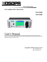
2.1 Front view
1. Microphone head
Please do NOT hit the microphone head when the
equipment is in use.
2. Microphone On/Off indicating ring
Indicating LED:
When the microphone is on, the indicating
light will be on.
The LED will be turned on as the
microphone On/Off indicating light is on
for calling all zones. The microphone head
indicting ring will be on, but the
microphone On/Off indicating light is off
10
9
8
7
6
5
1
2
3
4
MAG6588
Remote Paging Selector
CALL ALL
LEVEL(dBV)
∞
-13
-8
-3
0
+3

*Network Public Address System
4
when the system is not in status of paging
all zones.
3. Microphone Rod
Users can adjust the microphone angel flexibly.
4. Microphone base
4-leg Cannon socket:
1# leg for power and microphone head
indicating LEDs;
2# leg for input of voice signals;
3# leg for null;
4# leg for grounding of signal input.
5. Microphone plug
4-leg Cannon socket, corresponding
respectively to the four legs on the base.
6. Monitoring speaker
It is used to output the voices received.
7. Output level indicating LED
More indicating LEDs will be on as the output
volume increases.
8. LCD true color display
It is used to display the operating status and
operation interface of the paging station; the touch
screen is for selecting options.
9. Microphone On/Off indicating LED
The indicating LED is on when the user presses
"PAGING ALL" button to activate all zones. It
will also be on when any terminal is called.
10. Paging button
It is used to realize paging function for all zones. .
2.2 Rear view
广州市迪士普音响科技有限公司
Guangzhou DSPPA Audio Co.,Ltd.
CAUTION!
RISK OF ELECTRIC SHOCK
DO NOT OPEN
DC/+14V LAN HDMI RS232 RS485
HEADPHONE
NET AUDIO AUX OUT LINE IN
PHONES
VOL
警告
请勿打开,以免触电
POWER
1 2
3
4
5 6
7
8 9 10
11
COM COMTX RX A OUT-B OUT+
1. On/Off switch
When the button at "1" position is pressed down, the
system is powered on, while when the button at "1"
position is ejected, the system is powered off.
2. AC220V Power input wire
3. Network interface
It is used to connect to network switches.
4. HDMI output interface
Preserved.
5. Data Exchange Interface
It is the RS422 analog paging interface and is
reserved for extension by intelligent systems.
6. Data Exchange Interface
RS485 analog paging interface and is reserved
for extension by intelligent systems.
7. Monitoring headphone jack
It is for use of local monitoring and the volume
is adjustable.
8. Network audio output
9. Line-out audio output interface
It is used to connect the system to amplification
equipment.
10. Line-in audio input interface
It is used to connect to players, such as a DVD player
or a tuner.
11. Monitoring volume adjusting knob

*Network Public Address System
5
It is used to adjust the volume output to monitoring
headphone. Turn the knob clockwise to increase the
volume and anticlockwise to reduce the volume.
3. Connection Diagram
3.1 Application of MAG6588 Paging Station in the system
MAG6588 Paging Station can be deployed in any place where there is network access.
Note: ① The figure above only shows the connection of MAG6588 is basic application, please refer to the User
Manual of network controller for information about connection of the whole system.
② The figure above is only for demonstration, please refer to the connecting diagrams at the application
site for information about actual connection.
③ Connection of MAG6588 in the system can only be realized via a network switch and an address should
be configured in order to communicate with the controller and to paging the zones.
以 太 网
Other devices in network PA system
Other devices of network in
network PA system
System host
Paging station
广州市迪士普音响科技有限公司
Guangzhou DSPPA Audio Co.,Ltd.
CAUTION!
RISK OF ELECTRIC SHOCK
DO NOT OPEN
DC/+14V LAN HDMI RS232 RS485
HEADPHONE
NET AUDIO AUX OUT LINE IN
PHONES
VOL
警告
请勿打开,以免触电
POWER
COM COMTX RX A OUT-B OUT+
POWER
OFF ON
USB
NETWORK PUBLIC ADDRESS CENTRE
EMC MIC
FULL ALARMING
COMPACT DISC DRIVER

*Network Public Address System
6
CD/MP3 PLAYER
REPEAT
321
+554
USB
POWER
电源
3.2 Diagrams of local interface and connection of MAG6588 Paging
Station
The Paging Station can be used to output audio signals, and the audio channels are for use to connect amplifiers and
speakers to realize amplification at local places of the Paging Station. The user-friendly design can meet the needs
of large output power and multiple audio sources at the local places of terminals; the Paging Station also provides
auxiliary audio input interface for connecting to players.
The connection of local interfaces is as follows:
CD player
Monitoring headphone
广州市迪士普音响科技有限公司
Guangzhou DSPPA Audio Co.,Ltd.
CAUTION!
RISK OF ELECTRIC SHOCK
DO NOT OPEN
DC/+14V LAN HDMI RS232 RS485
HEADPHONE
NET AUDIO AUX OUT LINE IN
PHONES
VOL
警告
请勿打开,以免触电
POWER
COM COMTX RX A OUT-B OUT+
Power amplifier
Ethernet Switch

*Network Public Address System
7
4. Operation Instruction
4.1 Power on
After the system is correctly connected and the paging station is connected to power supply, the user can switch on
the power switch on rear panel to turn on the system. After the system is turned on, it enters the initialization status
and the message "System is starting please wait..." on screen of the paging station. During this process, the system
will load the previous operation information of the paging station.
It may take about 25 seconds to complete this process and display the following interface:

*Network Public Address System
8
On the interface shown above, the user can enter the system password by touching the corresponding numbers on
the interface and enter the main interface of the paging station, as shown below:
Main interface
The functions provided on the main interface include: Status operation of zones, display of zone status information,
zone paging/group paging/pre-listening programs/system setup/exit button.
4.2 Main interface
4.2.1 Display of time and network connection status
As shown above, the status bar on the main interface shows the current date and time information as well as the
network connection status.
Display of current
date and time
Display of current
Network connection
status
Select language
MIC On/Off

*Network Public Address System
9
4.2.2 Display of zone status information
The current operating status of each zone is displayed on the button of each zone, such as the name/ current task
and volume information of such zone. If the current paging station is connected to the network, the corresponding
button is in blue color, otherwise it is in gray color. As shown below:
"192.168.79.10" indicates the name or number of the zone;
"Offline" indicates the current task performed by the zone. In this picture, the current zone is offline.
"Volume 50%" indicates the current volume level of the zone, which cannot be adjusted on the paging
station but can be adjusted on the system controller. Please refer to the User Manual of System Controller
for detailed operation.
4.2.3 Zone paging operation
To call paging a zone:
In the first step, touch the "Zone Call" icon on the upper right side of the main interface, then touch the
zone to be called (a selected zone is surrounded by white box), and then touch the "Call" button to start
the calling. The message "Calling" will be displayed on the zone which is being called. Press the "Stop"
button to stop the calling and the zone will restore to its previous status.
To paging all zones, touch and select the "Zone Call" button on the upper right side of the main interface,
then touch the "Select all" button to select all zones and then touch the "Call" button to call all zones.
Touch the "Stop" button to stop the calling.
4.2.4 Group calling operation
To call a group:
In the first step, touch the "Group Call" icon on the upper right side of the main interface, then touch the
group to be called (a selected group is surrounded by white box), and then touch the "Call" button to start

*Network Public Address System
10
the calling. Press the "Stop" button to stop the calling and the group will restore to its previous status.
To call all zones, touch and select the "Group Call" button on the upper right side of the main interface,
then touch the "Select all" button to select all groups and then touch the "Call" button to call all groups.
Touch the "Stop" button to stop the calling.
4.2.5 Pre-listen a program
This operation allows monitoring the built-in programs on the network controller via the call station:
In the first step, touch the "Pre-listen program" icon on the right side of the main interface to enter the
player interface of pre-listened program, as shown below:
In the picture shown above, the directory shown on the left part indicates the built-in programs on the
network controller and external audio sources connected to the controller. Touch a directory (for instance,
touch the Courtesy), the songs in such directory will be displayed on the "Song" box on the right part.
Touch the song to be played and then touch the button to start playing and touch the
button to stop the playing. Touch and button to play the previous or the next
song.
The buttons on the right side of the song selection box can be used to switch to the songs on
the previous screen or the next screen, and the buttons can be used to select a song to be
played from the list of songs. After a song is selected, the user can touch the "Play" button to play the
song.
Touch the "+ or -" icons on button, or touch and drag the sliding
indicator on the volume bar to increase/reduce the monitoring volume; the icon on the interface
means Sound-off. The sound-off status can be canceled by touching the icon again.

*Network Public Address System
11
The button is used to set up playing modes, and the user can touch this button to call the desired
playing mode, as shown below:
: All songs in the selected director will be played in order.
: The selected song will be played in single loop mode.
: All songs in the selected directory will be played and broadcast.
: All songs in the selected directory will be played randomly.
: The selected song will be played for once and stops after the selected song is completed.
Among all directories shown on the monitoring interface, "Play a program, courtesy program, calisthenic
program and other, background music" are built-in audio sources of the network controller, and the
"external audio sources" include external audio equipment connected to the controller, such as a CD player
or a MP3 player. If no external audio source device is connected to the network controller, then no
equipment output is displayed. Therefore, please make sure that an external audio device has been
connected to the network controller before selecting this directory.
: to switch from pre-listen to broadcast. This interface means that current status is pre-listening.
: to switch from broadcast to pre-listen. This interface means that current status is broadcasting.
4.2.6 Zone broadcast
This operation is completed on the paging station.
Firstly, touch to enter broadcasting interface.

*Network Public Address System
12
Then click “Zone Call” to choose the zone you want to broadcast or touch “Group Call” to choose groups.
Then enter the interface above again to choose the music or program you want to play.
Choose zone or group.

*Network Public Address System
13
If no zone is selected you will see the following interface.
Click to play the music or program.
The interface will show “Playing”.

*Network Public Address System
14
4.2.7 Other operations
On the main interface:
"Invert Selection" button is to cancel the selection of a zone;
"Bell alarm" button is used to broadcast a bell alarm before calling.
"Page Up and Page Down" buttons are used to display the previous and the next page of zone for query
operation.
On the main interface, the " " icon is used to exit the main interface and return to the password input
interface.

*Network Public Address System
15
4.3 System Setup
On the main interface, touch the "System Setup" icon to enter the system setup interface, which is as shown below:
System setup interface
The operation items on system setup interface include:
Group Setup: to group the zones;
Network Setup: to set an IP address and subnet masks for the current paging station;
Time Setup: to set up the system time and date;
Backlight: to set up the backlight on time for the current paging station;
Microphone Setup: to set up the time period to automatically shut off the microphone on the current
paging station;
Log Management: to view and listen to the real-time audio log messages;
Screen Calibration: to calibrate the touch screen of the current paging station.
4.3.1 Group setup
On the "System Setup" interface, touch the "Group Setup" icon to enter the group setup interface.
The zone box is displayed on the right part of the interface and the group box is displayed on the left part.
The editing and operating buttons are listed on the bottom of the boxes and to the right of the box, there
are the selection buttons.
Before the grouping operation, touch the "Add" button and enter the name of the group on the pop-up
interface. Press the "Edit" button below the group box to modify the group name; press the "Delete" button
to delete a group that has been edited.
After the group name is set, select the desired group (the group name is highlighted, indicating that the
group has been selected), then touch the "Edit" button under the zone box on the right part to enter the
zone selection interface, which is as shown below (Next Page).

*Network Public Address System
16
On this interface, the selected group is listed and the zones may be allocated to such groups as desired.
All zones are displayed in the box on the right part of the interface, where the user can select the zones to
be added to the current group, and then touch the "Arrow" pointing to the left box, then the zone will be
moved to the left box, which means that the zone has been added to such group.
On the zone allocation interface:
" " button can be used to add or remove one single zone in the group;
" " button can be used to add or remove all zones in the group;
" " button can be used to return to the previous interface;
" " buttons can be used to switch to the previous page or the next page;
" " button is used to select the previous/next zone (group) of the current zone (group).

*Network Public Address System
17
After the group setup is completed, touch the "Return" button to exit the setup interface.
4.3.2 Network Setup
On the "System Setup" interface, touch the "Network Setup" icon to enter the network setup interface of the
current paging station. On this interface, the user can set up the IP address, subnet masks, gateway and server IP
address for the current paging station.
The user can touch the desired parameter and move the cursor to the parameter and then press the "DEL"
button on the keyboard to delete the existing digits and input the desired digits; or otherwise, the user may
touch and move the finger across the parameters to be modified and then press the "DEL" button on the
keyboard to delete the existing digits and enter the new digits.
After the setup is completed, the user should touch the "OK" button to confirm and exit the setup interface.
4.3.3 Time Setup
On the "System Setup" interface, touch the "Time Setup" icon to enter the system time setup interface. On this
interface, the user can set up the current system time and data.
To set up time and date, the user can touch the gray arrows in digit box to adjust the digit.
After the setup is completed, press the "OK" button to confirm and exit the setup interface, if the user
exits the setup interface without touching the "OK" button but by touching the "Return" button, then the
setup operation will not modify the previous time and date settings.
4.3.4 Backlight on time
On the "System Setup" interface, touch the "Backlight On Time" icon to enter the backlight on time setup interface
of the current paging station.
The user can touch the backlight on time value or the small circle before the Always on option, the small
circle will be ticked and marked by highlighted "√", indicating that the option has been selected. If no
operation is made for the selected backlight on time, the backlight of the screen will automatically turns
off, which helps to save energy and to extend the service life of the screen.
After the setup operation is completed, press the "OK" button to confirm and exit the setup interface, or
otherwise, the user can touch the "Return" button to cancel the setup operation and exit the setup interface.
4.3.5 Microphone Setup
On the "System Setup" interface, touch the "Microphone Setup" button to enter the interface to set up the automatic
off time of microphone.
The user can touch the time value or the small circle before the Always on option, the small circle will be
ticked and marked by highlighted "√", indicating that the option has been selected. If no signal in input
to the microphone for the selected time period, then the microphone of the current paging station and the
zone called will be automatically turned off.
After the setup operation is completed, press the "OK" button to confirm and exit the setup interface, or
otherwise, the user can touch the "Return" button to cancel the setup operation and exit the setup interface.
/