Page is loading ...

Public Address System
100V Network Terminal MAG6701
STBYNet Service
Timing
Signal
100V Backup
Protect
VOL+
VOL-Set
F1
USB
100V Network T erminal MAG6701
User Manual
Thank you for using our DSPPA public address system. Please read this User Manual carefully to make better
use of this equipment.
Guangzhou DSPPA Audio Co., Ltd
http: //www.dsppatech.com

This page is left blank for the user’s notes.

About this User Manual
This User Manual is available and effective upon completion of development of the 100V
Network Terminal MAG6701. The User Manual includes system description, matters
needing attentions in use, instructions on system connection, instructions on use of
product and technical specifications of the terminal. Please read this User Manual
carefully before connection, installation and use and operate in accordance with
corresponding instructions in the Manual.
This symbol on the rear panel indicates matters needing attentions, please use or operate the product
in accordance with corresponding instructions.
Please keep this User Manual in good custody for future use.
MAG—V0.3
Facture 2019-6-26

Matters needing attention
Please read the following before operating the product.
Warning
The following basic requirements must be strictly observed, to avoid potential personal injury and
equipment or property damages to you or any person nearby. The basic requirements include without
limitation to the following:
Power source/power cable
• Please disconnect the device from power source
by pulling the plug other than the power cord.
Pulling the power cord may result in damages.
• Please keep the power cord away from heat source.
Do not over-bend the power cord or place it
anywhere it can be stepped on or may cause to trip.
• This is connected to power source via the plug and
any failure or danger occurs, the user can
disconnect the device from power source by pulling
out the plug out from the socket, therefore, it is
required that the power socket should be located
somewhere with easy access.
• The device is not completely disconnected from
power source when it is switched "OFF". For sake
of safety, please disconnect the device from the
socket if it is not in user.
Positioning
• Please disconnect the device from power source
before relocating the device.
• For avoiding deformation of panels and damages
to internal components, please do NOT place the
device where there is heavy dust or violent
vibration, or where it is extremely cold or hot.
• Please keep this device off water drops or splash
or vase filled with water or any other articles of
similar nature.
Connection
• Please disconnect other equipment from power
source before they are connected to this product.
Please tune volume to its minimum level before the
device is powered ON or OFF.
• All terminals on the device marked with are
live and dangerous, and should be connected by
trained personnel.
When abnormal conditions are realized
• Please disconnect the device from power source
immediately in case the power cord is worn or
damaged or if the sound is suddenly cut off or any
abnormal odor or smoke comes out from the device,
and then have the device inspected and repaired by
professional personnel.
Precautions in Operation
• Please do NOT insert any finger into any gap or
opening of the device.
• Please prevent foreign objects (paper, plastics or
metal etc.) from being inserted or falling into any
gap or opening of the device. In such case, please
cut off power source immediately.
• Please do NOT put the body or any heavy object
on the device and do NOT operate the buttons or
switches or connections with excessive force.
Do NOT open
• Please do NOT remove the cover of the equipment,
otherwise you may get an electric shock.
• Do NOT attempt to remove any internal
component from the device, or to modify the
equipment in whatever manner. In case of any
abnormal condition, please stop using the device
immediately and have it inspected and repaired by
professional personnel.
Other Precautions
• Our company shall not be responsible for data loss
or damages due to improper use of unauthorized
modification to the device.
• The images and screen display in this Manual are
only for description and may be different from
screen images in actual operation. The screen
display depends on the product.

* * Content
i
Content
1. Product Description.................................................................................................................................................. 1
1.1 About MAG6701 network terminal................................................................................................................1
1.2 Features...........................................................................................................................................................1
2. Description of Appearance........................................................................................................................................2
2.1 Front panel...................................................................................................................................................... 2
2.2 Side panel........................................................................................................................................................3
2.3 Introduction to remote controller....................................................................................................................5
3. Connection Diagram................................................................................................................................................. 6
3.1 Application of MAG6701 in Network PA system..........................................................................................6
3.2 MAG6701 connection diagram...................................................................................................................... 6
4. Operation Instruction................................................................................................................................................ 8
5. Installation.................................................................................................................................................................8
6. Operating Instructions for Setting Up the Terminal on the Host Computer............................................................ 9
6.1 IP Address Setting...........................................................................................................................................9
6.2 Instruction for the Terminal Function Setting.............................................................................................. 10
Packing List.................................................................................................................................................................13
Specification................................................................................................................................................................14

* * Network PA System
1
1. Product Description
1.1
About MAG6701 network terminal
MAG6701 100V Network terminal is a network full digital analog-digital signal conversion processor based on
TCP/IP communication protocol. Dual-network redundancy design makes it possible to any place where there is
network. Remote digital data flow could export audio signal through this device, which is controlled by host.
There is built-in MP3 player, USB interface and SD card interface. You could also play local MP3 program
when there is no Network audio signal. It could execute timing function without host. There is one audio input
interface to connect with other audio equipment (such as DVD). There is one auxiliary audio output interface to
connect with other amplifiers to extend power. There is also a MIC interface to realize local paging.
1.2
Features
Dual-network redundancy design, able to work cross network segment
Able to be installed to any place where there is network.
Built-in MP3 player, with USB interface and SD interface to play local program
Independent execution of timing function without host
Support maximum 48kHz sampling rate, 16 bit digital audio decoding
Built-in 1×60W high fidelity digital amplifier, low power consumption
Able to play background music, emergency paging and alarm signal from system host
One auxiliary audio input interface, one auxiliary audio output interface, two MIC input interfaces,
one EMC emergency output interface and one short circuit output
Controllable volume and playing status of local output
LED indicator to show signal status, working status and information change
Support infrared remote control
Could set priority of audio source through Network

* * Network PA System
2
2.
Description of Appearance
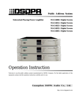
2.1 Front panel
STBYNet Service
Timing
Signal
100V Backup
Protect
VOL+
VOL-SetF1USB
100V Network Terminal MAG6701
1 2 3
4 5
6
7
8 9 10 11 12 13 14 15 16
1 button
U disk playing mode: to play previous song.
IP setting mode: move left/move right to view/set
parameters.
2 Play/Pause button
To control play/pause of local MP3 program
playback. When setting address, this button is
used to save the settings.
3 Network indicator (Net Service)
When this device is successfully connected to
host through Network, this indicator will be
turned on.
4 Timing indicator (Timing)
This device could execute timing function
without host control. When executing, indicator
will be turned on.
5 Amplifier output level indicator (Signal)
This indicator will be turned on when there is
signal output from this terminal. This indicator
will be brighter when increasing volume and it
will be darker when turn down volume.
6 USB button
U disk play/pause button. When setting IP, this
button could be used to exit setting status.
7 F1 button
Use when adjust volume. This button could be
used to switch among AUX IN, MIC IN/MIC 2,
and MP3.
8 Local setup button (Set)
Long press this button to enter IP address view
status. Press again to enter IP setup/modify status.
9 VOL- button
Play mode: to turn down volume.
View IP: to select parameter to be viewed.
Set up IP: to increase or decrease parameters.
10 Amplifier protection indicator
Pic. (1) Front panel

* * Network PA System
3
This indicator will be turned on when there is
short circuit.
11 100V input
When there is 100V input, this indicator will be
turned on.
12 Standby indicator (STBY)
Standby function indicator which is also a mute
function indicator. When there is a Network
alarm and emergency, it will be turned on. Alarm
and emergency signal could suppress mute
function.
13 VOL+ button
Playing mode: volume up.
IP viewing mode: to switch among parameters.
IP setting mode: to increase or decrease
parameters.
14 button
U disk playing mode: to play next song.
IP setting mode: move right to view/set
parameters.
15 Digital display screen and receiving
window of infrared remote
Digital display screen will display working status
and Network information. There is a built-in
receiving window of infrared remote to receive
remote control.
16 Screw fixing hole
This terminal could be installed on the wall.
There are four screw fixing holes which are used
to fix the device on the wall.
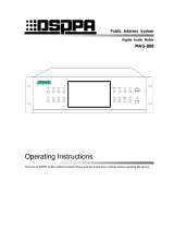
2.2 Side panel
24V
LAN2LAN1 Micro SDUSB Disk
AUX lN
AUX OUTMIC2 MIC1
COM SC
100V
IN
100V
OUT
+ +
请勿打开,以免触电
警告
~220V/50Hz
/100W
POWER
电源
广州市迪士普音响科技有限公司 Guangzhou DSPPA Audio Co.,Ltd.
100V网络定压壁挂终端
24V
IN
IN+
A
OUT+
OUT
COM
B
1 2
3
4 12 13 14
9 10 11
65
7
8
24V
LAN2LAN1 Micro SDUSB Disk
AUX lN
AUX OUTMIC2 MIC1
COM SC
100V
IN
100V
OUT
+ +
24V
IN
IN+
A
OUT+
OUT
COM
B
Pic. (2) Side panel

* * Network PA System
4
1 Network interface (LAN1/LAN2)
Dual Network design to connect with Network
POE.
2 USB interface (USB Disk)
Insert U disk or mobile hard disk with MP3
program inside to provide MP3player with program.
3 SD card interface (Micro SD)
If the inserted SD card has timing points, host will
play program when terminal is offline.
4 Auxiliary input interface (AUX IN)
To connect with audio source equipment (such as
DVD) to extend program source.
5 EMC prior playing output
Output signal of this interface is controlled by host.
6 100V external audio input
To connect with other standby amplifier.
7 Amplifier output (100V)
Built-in 1×60W digital amplifier with rated power
60W to connect with multiple speakers. Total power
of connected speakers should be no more than 60W.
8 On-demand terminal connection interface
To connect with on-demand terminal by using
8-core Network cable. Connection instruction
please refer to User Manual of on-demand terminal.
9 MIC2 interface
To connect with MIC.
MIC1 sound pickup
Built-in pickup window. Speak to this window to
broadcast.
Auxiliary output interface (AUX OUT)
To connect with other amplifiers to extend power.
12 AC220V power cable
To supply power.
13 Power switch (POWER)
Press “I” to turn on power supply. Press again to
turn off.
14 Heat dissipation

5
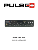
2.3 Introduction to remote controller
The structure of the remote controller is as shown on the right:
1. Mute.
2. Numbers:
To set IP address and parameters.
3. F5:
After inserting U disk, press F5 to play and stop.
4. Previous one
CH+ is used to play previous program.
5. Volume down
V- is used to turn down output volume.
6. F7: play/pause
To play or pause.
7. Enter
Under free status, press Enter to adjust output.
Bass: 0-15 adjustable
Under other status, press Enter to confirm.
8. Next one
CH- is used to play next program.
9. Cancel
Under free status, press Cancel to adjust output.
Treble: 0-15 adjustable
Under other status, press Cancel to cancel.
10. Volume up
V+ is used to turn up volume.
11. F3:
To view/change IP.
Press once to enter viewing status. Press CH+/CH- to select parameters. Then press F3 to set. After setting,
press Enter to save or Cancel to cancel.
12. F1: volume setup
Select audio source and press V+ and V- to adjust volume. (AUX1 is auxiliary input. MIC1 is microphone input.
MP3 is Network or U disk audio source.)
13. Standby
Pic. (3)
1
8
13
2
3
4
5
6
7
12
11
10
9

6
3. Connection Diagram
3.1 Application of MAG6701 in Network PA system
Note:
1. This diagram is only the application diagram of MAG6701. As for the connection diagram of the
whole system please refer to user manual of network PA system control host.
2. This diagram is only one example. As for specific connection method, please refer to system
connection diagram.
3. The connection of MAG6701 terminal must be realized through network switch and only by setting
corresponding IP address can this device be connected with host.
3.2 MAG6701 connection diagram
Except for MP3 player and the network audio source, there is one auxiliary input and one auxiliary output to
connect with other audio sources and power amplifiers. The customized design can satisfy demands for high
power and multiple audio sources. The MP3 player and network audio stream can realize sound amplification at
most public places.
STBYNet Service
Timing
Signal
100V Backup
Protect
VOL+
VOL-SetF1USB
100V Network T erminal MAG6701
STBYNet Service
Timing
Signal
100V Backup
Protect
VOL+
VOL-SetF1USB
100V Network T erminal MAG6701
STBYNet Service
Timing
Signal
100V Backup
Protect
VOL+
VOL-SetF1USB
100V Network T erminal MAG6701
STBYNet Service
Timing
Signal
100V Backup
Protect
VOL+
VOL-SetF1USB
100V Network T erminal MAG6701
Ethernet
Other devices
Other networks and
devices
Control host
Terminal
Terminal
Terminal
Terminal
POWER
OFF ON
USB
NETWORK PUBLIC ADDRESS CENTRE
EMC MIC
FULL ALARMING
COMPACT DISC DRIVER

7
CD/MP3 PLAYER
REPEAT
321
+554
USB
POWER
电源
24V
LAN2LAN1 Micro SDUSB Disk
AUX lN
AUX OUTMIC2 MIC1
COM SC
100V
IN
100V
OUT
+ +
请勿打开,以免触电
警告
~220V/50Hz
/100W
POWER
电源
广州市迪士普音响科技有限公司 Guangzhou DSPPA Audio Co.,Ltd.
100V网络定压壁挂终端
24V
IN
IN+
A
OUT+
OUT
COM
B
1 2
3
4 12 13 14
9 10 11
65
7
8
24V
LAN2LAN1 Micro SDUSB Disk
AUX lN
AUX OUTMIC2 MIC1
COM SC
100V
IN
100V
OUT
+ +
24V
IN
IN+
A
OUT+
OUT
COM
B
The schematic diagram of interface connection of the device is shown in the following figure:
1×60W output:
Amplifier
Note: 100V output and input cable cannot be tangled together to avoid signal interference.
Ethernet switch
MIC
Connect to a 60W speaker
LAN2LAN1 Micro SDUSB Disk
MIC1
AUX lN
AUX OUT
MIC2
24V
IN- IN+ A B
OUT
+
OUT
COM
MIN MAX
MUTE
EMC OUT
24VSCCOM
~220V/5 0Hz/10A
AUDIO O UTPUT
COM 100V
广州市迪 士普音 响科技有 限公司 Gu angzho u DSPPA Au dio Co.,Ltd.
网络化播 放功放
请勿打开,以 免触电
警告
RISK OF ELEC TRIC SHOCK
DO NOT OPEN
CAUTIO N!
F8AL
24V
COM SC
100V
IN
100V
OUT
+ +
Public Address Amplifier
POWER CLIP SIGNAL PROT TEMP
VOLUME
0 10
91
2 8
3
7
64
5
PROFESSIONAL AMPLIFIER
100V standby amplifier
On-demand terminal
Power amplifier
Public Address Amplifier
POWER CLIP SIGNAL PROT TEMP
VOLUME
0 10
91
2 8
3
7
64
5
PROFESSIONAL AMPLIFIER

8
4. Operation Instruction
1. Volume adjustment:
a) Press “VOL+” or “VOL-” to adjust playing volume. Press “F1” to switch between volumes of
different audio source. Audio source options are AUX.1, MIC.2, MP3.3 (“AUX.1” is input volume.
“MIC.2” is acquisition volume. “MP3.3” is volume of AUX OUT output.)
b) After setting, it will go to countdown status automatically.
2. IP address modification:
a) Long press “Set” to enter IP address viewing mode.
b) Press “VOL+” or “VOL-” to select parameter that needs to be changed. (local IP, sub IP, gateway, and
subnet mask). After selecting, it will show parameters automatically.
c) Press “Set” again to enter IP address modification status. When parameter is flashing, press or
to switch between parameters. Press “VOL+” or “VOL-” to increase and decrease. After
changing, press “Play/Pause” key to save parameters. If you do not press “Play/Pause” key, your
change will not be saved.
3. “IP” represents IP address. “SIP.1”/“SIP.2” represents IP address of sub-device. “GATE” represents gateway
(better not change). “MASK” represents subnet mask (better not change).
4. When the host is in playing status, insert U disk and press USB. Host will show “err” which means it cannot
play songs in U disk because priority level of host is higher than that of U disk.
Note: when eject or insert SD card, host must be power-off. Otherwise, SD card will be damaged. When digital
tube shows “err”, your operation is invalid.
5. Installation
Note: user could find location of screws according to the installation diagram.
Installation diagram
STBYNet Service
Timing
Signal
100V Backup
Protect
VOL+
VOL-SetF1USB
100V N etwork T erminal
172mm
150mm

9
6. Operating Instructions for Setting Up the Terminal on the
Host Computer
6.1 IP Address Setting
This speaker can be customized to modify the network parameters. Please read this section in detail if you need
to use this function. The alteration methods are as follows:
Method 1:
1. IP address of host computer/ computer alteration requires IP address of host computer/ computer and the
terminal address in the same network segment. For example, the terminal IP address is 192.168.40.5, while
the IP address of host computer/ computer should be 192.168.40.XX (Note: the setting IP can not appear
IP conflict phenomenon);
2. Input the IP address of the terminal on IE browser after connecting host computer/ computer and the
terminal, and then access into the below as shown in Pic. 1;
3. Click “Confirm to alteration”to save the changes successfully after altering the terminal IP address or
server address on “Network configuration”.
(Pic. 1)
Method 2:
1. Enter the host software "Settings" -> "System Maintenance" -> "Device Maintenance"
2. Find the IP address of the terminal label, select and click Modify.
3. As shown in Pic. 2, modify the parameters and click OK to see the interface shows success.

10
(Pic. 2)
6.2 Instruction for the Terminal Function Setting
As the Method 1 in 6.1 above, it ensures host computer/ computer and the terminal in the same network
segment, and input the IP address of the terminal on IE browser to get into the following page, and then click
“Public Address” for a further function setting to the terminal (as the picture below):
1. Off-line schedule function: Enable mode and disable mode are optional, to ensure that there is no switch to
100V state, according to their own needs to start offline schedule point function. When you need to start

11
the function, select "Enable "option and press the" Submit "button; instead, select" Disable "option.
2. 100V constant voltage backup function: a. Without network; if chose “Enable” before, when the network
play is abnormal or the terminal drops, it will switch to 100V audio signal automatically; if chose
“Disable” before, when the network is abnormal, it will not switch to 100V audio signal. b. Without Power;
whether chose “Enable” or “Disable” before, it will switch to 100V audio signal automatically.
3. On-demand panel terminal function: to ensure that there is no switch to 100V state, select "fixed" option
for the terminal being fixed for the on-demand panel terminal, and when select the "dynamic" option, plug
in the on-demand panel for the on-demand panel terminal; not inserted for the ordinary playback terminal.
4. Local network preference: Three priority modes. to ensure that there is no switch to 100V state, when the
"local" option is selected, the local source is output first, and the "network" option is the same. When
"mixed" is selected, both local and network are output at the same time.
5. Microphone type selection: According to their own needs to select the condenser or dynamic type to ensure
that there is no switch to 100V state.

12
Safety Precautions
1. Safety Precautions
Please do NOT connect this device to the power source, before the system is correctly wired.
It is important to ensure that input voltage to the device is the same as required voltage of the device,
otherwise the device may be damaged.
There is dangerous voltage in the device, which may cause personal electric shock. Please do NOT
open the case without permission, to avoid potential risks of electric shock.
The device is not completely disconnected from power source when it is switched "OFF". For sake of
safety, please disconnect the device from the socket if it is not in use.
Please do NOT place the device where it is extremely cold or hot.
Good ventilation must be provided in the working environment of the device, to avoid excessive
temperature during its operation, which may cause damages to the device.
Please unplug the device from power socket in raining and wet days or if the device is not in use for a
long time.
Please disconnect the power plug from sockets, to ensure the device has been completely
disconnected from power source, before any component is removed from or re-installed in the device
or before any electric connector of the device is disconnected or reconnected.
In case of any failure of the device, please do NOT open the case and repair without permission from
a professional personnel, to avoid accident or additional damages to the device.
Please do NOT place any corrosive chemicals near or on the device.
2. Matters Needing Attention
Our company provides a three-year free warranty service (including free replacement parts) over
quality issues as from the date of purchase, provided that the device is installed and used in
accordance with requirements specified in the User Manual.
For warranty, the user must show the Warranty Card and the receipt kept by the user and purchase
invoice of the device as supporting documents.
The following conditions are beyond the scope of warranty:
1.Product damage due to improper installation, use or handling;
2.Product damage due to abnormal conditions (such as excessive power source voltage or ambient
humidity);
3.Product damage due to acts of God;
4.Product SN is changed, altered or removed;
5.Product has been repaired or modified by any person without duly authorization from our
company;
Please keep the User Manual and Warranty Card in good custody.
For issues and precautions not mentioned in this User Manual, if required, please contact the
distributor or visit our website at http://www.dsppatech.com.
In case of any failure in the warranty period, please contact service personnel (or distributor) of our
company for service. The company shall not be made liable for damages due to unauthorized
dis-assembly or maintenance or service by unauthorized personnel.

13
Packing List
No.
List
Quantity
1
MAG6701
1 set
2
1500MM/AV terminal audio cable
1 pc
3
3000MM/8-core network cable
1 pc
4
User Manual
1 copy
5
Warranty card
1 copy
6
Certificate
1 copy
7
7P green plug 3.81MM plug
1 set
8
8P green plug 2.54MM plug
1 set
9
AMP crystal head8P8
2 pcs

14
Specification
Indicator item
Indicator
AUX IN
Input sensitivity
300 mV±30mV
Frequency response
80Hz-16kHz(±3dB)
Distortion
≦1%
Noise
14mV
Signal-to-noise ratio
≥77dB
AUX OUT
Input sensitivity
1000mV±100mV
Frequency response
35Hz-20KHz(±3dB)
Distortion
0.1%
Noise
0.12 mV
Signal-to-noise ratio
≥77 dB
Maximum output
power of the built-in
power amplifier
Single channel mode
60W/160Ω
Maximum harmonic distortion of the built-in power
amplifier
≦1%
MIC input
Input sensitivity
3.5 mV±1mV
Frequency response
80Hz-16kHz(±3dB)
Distortion
≦0.5%
Noise
14mV
Signal-to-noise ratio
≥77 dB
USB/SD
/NET
Play MP3
Input sensitivity
100V±5V
Frequency response
8Hz-16kHz(±3dB)
Distortion
≦0.4%
Noise
14 mV
Signal-to-noise ratio
≥77dB
Capacity of external U disk supported
32GB
Voltage range of power supply voltage
AC220V/50Hz
Overcurrent, overheat, over-voltage and under-voltage
protection
Support
Package dimension (L×W×H mm)
330×270×125
Machine dimension (L×W×H mm)
222×195×56
Net weight
2.35kg
Gross weight
3.2kg

15
Guangzhou DSPPA Audio Co., Ltd.
Caution
● The device is not completely disconnected from power source when it is switched "OFF". For sake of safety,
please disconnect the device from the socket if it is not in use.
● Please keep this device off water drops or splash or vase filled with water or any other articles of similar
nature.
● Please do NOT remove the cover of the equipment, otherwise you may get an electric shock. Where
necessary, repair to the equipment should be conducted by qualified professionals.
● All terminals on the device marked with are live and dangerous, and should be connected by trained
personnel.
● This is connected to power source via the plug and any failure or danger occurs, the user can disconnect the
device from power source by pulling out the plug out from the socket, therefore, it is required that the power
socket should be located somewhere with easy access.
/