Page is loading ...

Public Address System
POE Network Display Terminal POE6401
USB
F1
Set
VOL+
VOL-
STBY
Net Service
Timing
Signal
P L A Y
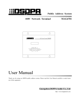
Network Terminal POE6401
User Manual
Thank you for using our DSPPA public address system. Please read this User Manual carefully to
make better use of this equipment.
Guangzhou DSPPA Audio Co., Ltd.
http://www.DSPPA.com
http://www.dsppatech.com

About the instructions
The instructions are used from the development completion date of the poe public address display
terminal MAG6401. The instructions include product introduction, precautions for
use, instructions for system connection, instructions for product use, and technical
indicators of the product and other contents of the four-way network public address
terminal. Prior to connection, installation and use, the user shall carefully read the
instructions, and conduct operation according to indication in the instructions.
The instructions with the label on the back panel of the machine are the matters to be notice.
Please conduct use or operation according to these instructions during use.
Please properly keep the instructions in case of need.

Precautions
Please carefully read the following careful prior to operation and use.
Warning
In order to avoid the possible personal injuries, equipment or property loss to you and
others surrounding, please comply with the following basic precautions. These precautions
include but are not limited to the following cases:
Power / power cord
• When the power cord plug is unplugged,
please seize the plug instead of the power cord.
Direct dragging of the power cord may lead to
damages.
• Please do not place the power cord near the
heat source. Do not bend the power cord
excessively, and do not place it at the position
possibly trampled or causing trip.
• The equipment is connected with the electric
network source through the power cord plug.
In case of any failure or danger of the
equipment, connection between the equipment
and the power grid can be disconnected by
unplugging the power cord plug. Therefore, it
is required to place the power socket at the
position convenient for swap operation of the
power cord.
• When the power supply switch of the
equipment is in the "off" state, the machine is
not disconnected completely with the power
grid. The power cord plug shall be unplugged
from the power socket for safety when the
equipment is not used.
Laying position
• Please disconnect the power supply prior to
movement of the equipment.
• In order to avoid panel deformation or
damages to the internal components, do not
place the equipment in the extremely cold or
hot environment with dust or vibration.
• The equipment cannot be subject to water
drop or water splash, and the vase filled with
water and other articles cannot be placed on
the equipment.
Connection
• Before the equipment is connected with
other equipment, please disconnect the power
supply of these equipment firstly. Before the
power switch of the equipment is turned on or
turned off, please adjust all volumes to the
minimum.
• The terminal marked with symbol in the
equipment represents hazardous live, and
operation of connecting these terminals shall
be completed by the personnel guided.
When the abnormal circumstance is realized
• In case of any wear or damage of the power
cord, if the sound is suddenly interrupted
during equipment use, or abnormal smell or
smoke is sent therefrom, the professionals
shall overhaul the equipment.
Precautions for operation processing
• Please do not insert the finger into any gap
or opening of the equipment.
• Avoid any foreign matter (paper, plastic or

4
metal) from inserting or falling into any gap or
opening of the equipment. If it happens, please
immediately disconnect the power supply.
• Do not press the body on the equipment, or
place any heavy object on it. Avoid
overexertion during button or switch operation
or machine connection.
Please do not open
• Please do not open the machine cover plate
at discretion, so as to prevent electric shock.
• Please do not try to disassemble internal
parts of the equipment or conduct
transformation of any form. In case of any
anomaly, please immediately stop use, and
invite the professionals for overhaul.
Other precautions
• In case of any data loss or damage caused to
the equipment due to improper use or
transformation without authorization, our
company shall not assume any responsibility.
• Illustration in the manual is only used for
instructions, which may be different from the
screen appearing during actual operation of
the device. The real object shall prevail.

* * Contents
Network display terminal POE6401 Network display terminal POE6401
I
Contents
I. Product description ................................................................................................................................................. 1
1.1 About POE6401 display terminal ................................................................................................................. 1
1.2 Performance features .................................................................................................................................... 1
II. Description of the external appearance .................................................................................................................. 2
2.1 Introduction of the front panel ...................................................................................................................... 2
2.2 Introduction of the side panel ....................................................................................................................... 3
2.3 Instructions for remote controller structure .................................................................................................. 4
III. Connection legend ............................................................................................................................................. 6
3.1 Schematic diagram of application of POE6401 terminal in the system ....................................................... 6
3.2 Schematic diagram of connection of interface of POE6401 terminal .......................................................... 6
IV. Instructions for use and operation ......................................................................................................................... 8
Packing list ............................................................................................................................................................... 10
Performance specifications ....................................................................................................................................... 11

* * Network Public Address System
Network Display terminal POE6401
1
I. Product description
1.1 About POE6401 display terminal
POE6401 network display terminal is a networked all-digital analog-digital conversion signal processor based
on TCP/IP transmission protocol, which adopts the dual network redundancy design, and can be coupled at any
place with access to network. The remote audio data stream can output the audio signal through the machine
with intelligent control of the host machine; MP3 player is built in the machine, and is provided with USB
interface and SD card socket. MP3 program can be played when the network audio stream signal is not played;
it can be separated from the host machine to implement the timing point independently; a-way auxiliary audio
input interface is used to connect other audio source device (such as DVD), and a way auxiliary audio output
interface is used to connect other power amplifiers, so as to expand the power; there is a way microphone
interface, so as to realize local paging and so on.
1.2 Performance features
It can work across the network segments.
It can be coupled at any place with access to network.
It has MP3 player, and is arranged with USB socket and SD socket, which are used to play the local
program.
It can be separated from the host machine to implement the timing point independently.
It supports maximum 48kHz sampling rate 16bit digital audio bit stream decoding.
2×10W or 1×20W high fidelity digital power amplifier is built in with low power consumption
settings.
It can play the background music, emergency paging, and alarm signal and so on from the system
host machine.
It has a way auxiliary audio input interface, a way auxiliary audio output port, a way EMC
emergency output port and 1-way short circuit output.
The local output volume and local playing state are controllable.
Signal state LED indication, working state and information change digital display
It can be controlled by the infrared remote controller.
It supports power supply in POE IEEE802.3AT mode.

* * Network Public Address System
Network Display terminal POE6401
2
II. Description of the external appearance
2.1 Introduction of the front panel
1 Digital display screen and infrared remote
control receiving window
The digital display screen indicates the working
state and network information state of the machine.
The infrared remote controller is inserted at the
upper right corner of the display screen, and the
machine state can be controlled with the infrared
remote control.
2 STBY
The standby function indicator lamp is equal to the
mute function, and the network alarm and
emergency signal can open it. That is to say, the
alarm and emergency signal can cancel the mute
state.
3 Net Service
When the machine and the host machine are
successfully connected through the network, the
indicator lamp is on.
4 Timing
The terminal can be separated from the host
machine to implement the timing point edited.
When the terminal can be separated from the host
machine to implement the timing point, the
indicator lamp is on.
5 Signals
When the signal is output from the terminal power
amplifier, the indicator lamp is on. When the power
amplifier volume is gradually increased, the
indicator lamp is brightened gradually; when the
volume is gradually decreased, the indicator lamp is
darkened gradually.
6 Screw fixing hole
The terminal can be installed at the positions
similar to the wall. There are 4 fixed screw holes
on the machine, and the machine is fixed on the
wall surface with the with-machine screws during
installation.
7 Play / pause key
When the local MP3 program is played, the key
is used to conduct play / pause operation; during
address settings, the key is used to save setting

* * Network Public Address System
Network Display terminal POE6401
3
operation results.
8 USB key
U disk play / stop button; press the key to quit
setting state during address setting operation.
9 Key
Play mode: select previous track play function.
Set IP mode: move a screen leftwards / move a
bit leftwards, select viewed / set parameter
10 F1 key
It is used during volume adjustment, and it is
switched among three audio sources of auxiliary
input, microphone input and MP3 play volume.
11 Key
Play mode: select next track play function.
Set IP mode: move a screen rightwards / move a
bit rightwards, select viewed / set parameter
12 Set
Long press the key to enter IP address view state,
press it again, and enter IP setting state.
13 VOL-key
Play mode: volume down function.
View IP mode: switch and select the viewed
parameters.
Set IP mode: parameter plus-minus function.
14 VOL+key
Play mode: volume up function.
View IP mode: switch and select the viewed
parameters.
Set IP mode: parameter plus-minus function.
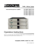
2.2 Introduction of the side panel
Micro SDUSB Disk
AUX lN
MIN MAX
Speaker
+
EMC OUT
24V
AUX OUT
MIC2
MIC1
24V
IN- IN+ A B
OUT
+
OUT
COM
SCCOM
MUTE
2 3
4 5
6
7
8 10 119
POWER
广州市迪士普音响科技有限公司
Guangzhou DSPPA Audio Co.,Ltd.
网络播放终端
请勿打开,以免触电
警告
RISK OF ELECTRIC SHOCK
DO NOT OPEN
CAUTION!
POE LAN
13
112
1 POE LAN
Connect 48V output, support AT mode, POE
output port power outputs above 25.5W POE
switch
2 USB Disk
Insert U disk at the interface or connect the
portable hard disk and other memory device, and
provide the program source for the built-in MP3
player.
3 Micro SD
Insert the SD card saved with host timing point at
the socket. When the terminal is disconnected,
the host machine plays the audio source at the
definite time.
4 Auxiliary input interface (AUX IN)
Connect the audio source device (such as
Figure (2) Side
panel

* * Network Public Address System
Network Display terminal POE6401
4
DVD) to expand the program source for the
machine.
5 LED matrix screen connecting port (not
opened to the machine)
6 MIC1 pickup window (not opened to the
machine)
The built-in microphone pickup window can
directly release audio broadcasting to the window
(not opened).
7 Microphone silent adjustment
MIC1 silent depth adjusting knob.
8 Speaker
2×10W digital power amplifier is built in the
machine (note: please adopt two-way
simultaneous output with caution due to POE
switch supply power restrictions). The output
port power is 10W. They are connected with two
constant resistance (4Ω) sound box.
9 EMC forced plug play output
The signal output from the interface is
controlled by the host machine.
10 Auxiliary output interface (AUX OUT)
It is connected with other power amplifiers,
so as to expand the terminal power.
11 MIC2 interface
Connect the microphone to realize local paging,
site talking and other functions. (Not opened to
the machine)
12 Power amplifier cooling window
13 Power (POWER)
Press "I" position to turn on the power supply and
bounce "I" position to turn off the power supply.
2.3 Instructions for remote controller structure
The structure of the remote controller is as shown in the right figure:
1. Mute key.
2. Number key:
It is used when IP address is set, and the parameter value is set.
3. F5:
When U disk is inserted, press F5 for play / stop.
4. Previous track selection key:
CH+ is used to select the previous program of the current track.
5. Volume down:
V- is used to turn down the output volume of the terminal.
6. F7: play / pause key:
Press the key repeatedly for switching between play on demand and pause.
7. Enter key:
Press Enter key to adjust output at the idle state
Bass components (circulating adjustment from 0 to 15)
8. Next track selection key:
CH- is used to select the next program of the current track.
Figure (3)
1
8
13
2
3
4
5
6
7
12
11
10
9

* * Network Public Address System
Network Display terminal POE6401
5
9. Cancel key:
Press Cancel key to adjust output at the idle state
High tone components (circulating adjustment from 0 to 15), and press Cancel key for cancellation at
other states.
10. Volume up:
V+ is used to turn up the output volume of the terminal.
11. F3:
IP address view / modification key. Press it to enter view state, press CH+/CH- to select the
parameter to the view, press F3 to enter the setting state, and press Enter for saving after
modification. Other, modification is invalid. Press Cancel to quit without saving.
12. F1: volume setting key:
Select the audio source to be modified. Press V+ and V- to modify the volume after selection.
(AUX1 is auxiliary input, MIC1 is microphone input, and MP3 is network audio source or U disk)
13. Standby key

* * Network Public Address System
Network Display terminal POE6401
6
III. Connection legend
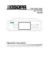
3.1 Schematic diagram of application of POE6401 terminal in the system
Note:
1. Only the schematic description for connection of rough application of POE6401 terminal is made in the
above figure. For connection of the whole system, please refer to operation instructions for the networked
control host.
2. It is illustrated by examples in the above figure. For specific connections, please refer to the schematic
diagram of system connection.
3. POE6401 terminal must be connected in the system through the network switch, and the corresponding
address shall be arranged for connection with the host machine.
3.2 Schematic diagram of connection of interface of POE6401 terminal
Except for MP3 player and the network audio source carried in the machine, a way auxiliary input and a way
auxiliary output are also arranged to connect other audio sources and power amplifiers. The customized design
can satisfy demands for high power and multiple audio sources on terminal site. The peripheral audio source
and other power amplifiers may not be connected in the application without such individual demands. The MP3
Ethernet
Other equipment of the network
broadcasting system
Network
broadcasting system
Other networks or
equipment
Termin
al
Termin
al
Termin
al
Termin
al
COMPACT DISC DRIVER
POWER
EMC MIC
NETWORK PUBLIC ADDRESS CENTRE
OFF ON
MAG 6182
USB
TOUCH PAD
FULL ALARMING
COMPOCT
Control host of the network
broadcasting system
USB F1 Set
VOL+
VOL-
STBY
Net Service
Timing
Signal
P LA Y
Network T erminal POE6401
USB F1 Set
VOL+
VOL-
STBY
Net Service
Timing
Signal
P LA Y
Network T erminal POE6401
USB F1 Set
VOL+
VOL-
STBY
Net Service
Timing
Signal
P LA Y
Network T erminal POE6401
USB F1 Set
VOL+
VOL-
STBY
Net Service
Timing
Signal
P LA Y
Network T erminal POE6401

* * Network Public Address System
Network Display terminal POE6401
7
player and network audio stream carried in the machine can realize sound amplification at most public places.
The schematic diagram of interface connection of the machine is shown in the following figure:
The power amplifier is 2×10W output (note: please adopt two-way simultaneous output with caution due to
POE switch supply power restrictions), which is as follows:
AUX
OUT
AUX lN R
Micro SDUSB Disk
AUX lN L
MIN MAX
Speaker
+
EMC OUT
DC
MIC1
24V
IN- IN+ A B
OUT
+
OUT
COM
SC
COM
MUTE
CD player
Power
amplifier
Connect two 4Ω, 25W
constant resistance sound
box

* * Network Public Address System
Network Display terminal POE6401
8
IV. Instructions for use and operation
1. Volume modification
a) Press "VOL+" or "VOL-" key to directly adjust the play volume, press "F1" key for switching among
various volumes, switch it to the current audio source, and adjust the volume of the audio source. The
audio sources which can be switched are AUX.1, MIC.2 and MP3.3 ("AUX.1" represents the input
volume, "MIC.2" represents microphone collection volume, and "MP3.3" respects AUX OUT output
volume).
b) It will automatically switch to the timing state after setting operation.
2、 Modify IP address:
a) Long press "Set" key to enter IP address to view the state.
b) Press "VOL+" or "VOL-" key to select the parameters to be modified (the machine IP, slave machine
IP, gateway and subnet mask); after selection, it automatically switches to display the corresponding
parameter value.
c) At the moment, press "Set" key to enter IP address modification state. When the parameter flashes,
press key or key to switch the parameter bit; press "VOL+" or "VOL-" key to increase /
decrease the parameter. After modification, press "play / pause" key to save the parameter. If "play /
pause" key is not pressed, the parameter modification is invalid operation.
3、 If the nixie tube displays "IP", it represents IP address of the machine, “SIP.1”/“SIP.2” represents IP
address of the slave machine, “GATE” represents the gateway (no modification), and “MASK” represents
the subnet mask (no modification).
4、 When the host machine is at the playing state, insert U disk, press USB to display "err" wrong indication,
which indicates that the song in U disk cannot be played. Because the priority level of the host machine is
higher than that of U disk.
Note: turn off the power supply during SD card swapping. Otherwise, it may damage SD card; when the nixie
tube displays "err", it indicates invalid operation.

* * Network Public Address System
Network Display terminal POE6401
9
Precautions
1. Safety precautions
Before the system line is well connected, do not insert the network cable crystal head of the
equipment into 48V POE switch.
Guarantee that the output voltage of POE switch is 48V. Otherwise, it cannot work, and the equipment
may be burnt.
There is a dangerous voltage in the machine, and the voltage is sufficient to cause an electric shock of
personnel. Please do not open the shell without authorization, so as to avoid the risk of electric shock.
Do not place the equipment in the overcooling or overheating place.
Guarantee good ventilation of the working environment, so as to avoid the heating during work, and
damages to the equipment due to too high temperature.
Please unplug the power plug on the rainy and humid day or when it is not used for a long period.
Before any component of equipment is removed or reassembled, or any electric apparatus plug or
other lines are disconnected or reconnected, the network cable crystal head must be unplugged, in
order to ensure that the equipment is completely disconnected from the grid.
In case of the equipment failure, the nonprofessional shall not remove the shell for maintenance
without permission, so as to avoid the unexpected accident or aggravate the damage degree of the
equipment.
Do not place any corrosive chemical near or on the equipment.
2. Precautions for after-sales service
Our company will offer three-year free warranty (including provision and replacement of parts for
free) for all quality problems appearing during the installation and use in accordance with this
instruction and in the normal use scope since the date of purchase.
In case of warranty, the user must show the warranty card, the copy saved by the user and sales
invoice as the evidence.
The following circumstances are not covered in the free guarantee scope:
1.Damages to products caused due to incorrect installation, use or handling;
2.Damages to products caused due to abnormal circumstances (for example, too high supply voltage
or environmental humidity);
3.Damages to products caused due to natural and man-made calamities and other unexpected
accidents.
4.The number of the product body is converted, altered or removed;
5.The products are repaired or refitted by the person not authorized by the company;
Please properly keep the instructions and warranty card.
For the non-mentioned problem or precautions in the instruction, please contact the dealer or visit our
company's web page http://www.DSPPA.com; http://www.dsppatech.com
In case of failure in the warranty period, please contact our company's service personnel (or contact
the dealer) for repair or handling. For damages caused due to disassembly without authorization or
maintenance by technician not authorized by our company, our company will not assume
responsibility for free warranty.

* * Network Public Address System
Network Display terminal POE6401
10
Packing list
Serial
number
List
Quantity
1
Network display terminal
1 set
2
1500MM / dual modem audio cable
1 piece
3
3000MM / 8-core network cable
1 piece
4
Instructions
1 copy
5
Guarantee card
1 copy
6
Conformity certificate
1 copy
7
7P green plug 3.81MM plug
1 set
8
4P green plug 3.81MM plug
2 sets
9
AMP crystal head 8P8
2 pieces
10
Gold 3.5MM audio plug
1 pieces

* * Network Public Address System
Network Display terminal POE6401
11
Performance specifications
Indicator item
Indicator
AUX IN
Input sensitivity
1000 mV
Frequency response
20Hz-20kHz
Distortion
0.1%
Noise
1mV
Signal-to-noise ratio
80 dB
AUX OUT
Output sensitivity
1000mV
Frequency response
2Hz-26kHz
Distortion
0.05%
Noise
0.12 mV
Signal-to-noise ratio
77 dB
Maximum output power of
the built-in power
amplifier
Independent channel mode
10W/4Ω
Maximum harmonic distortion of the built-in power
amplifier
0.3%
MIC microphone input
Input sensitivity
10 mV
Frequency response
20Hz-20kHz
Distortion
0.5%
Noise
2 mV
Signal-to-noise ratio
75 dB
USB/SD
/NET
Play MP3
Output sensitivity
7.8V
Frequency response
10Hz-20kHz
Distortion
0.05%
Noise
1 mV
Signal-to-noise ratio
80dB
Capacity of external U disk supported
32GB
Range of power supply voltage
45-256V/50Hz
OVERCURRENT, overheat, over-voltage and
under-voltage protection
Conforming to
Package size (L×W×H mm)
270×210×110
Machine size (L×W×H mm)
190×195×50
Net weight
1.45kg

Guangzhou DSPPA Audio Co., Ltd.
Attention
When the power supply switch of the equipment is in the "off" state, the machine shall not be disconnected
completely with the grid power supply. The power plug shall be unplugged from the socket for safety when
the equipment is not used.
The equipment cannot be subject to water drop or water splash, and the vase filled with water and other
articles cannot be placed on the equipment.
Please do not open the machine cover plate at discretion, so as to prevent electric shock. The professional
with professional certificate shall conduct repair if necessary.
• The terminal marked with symbol in the equipment represents hazardous live, and operation of
connecting these terminals shall be completed by the personnel guided.
The equipment is connected with the electric network source through the power cord plug. In case of any
failure or danger of the equipment, connection between the equipment and the power grid can be
disconnected by unplugging the power cord plug. Therefore, it is required to place the power socket at the
position convenient for swap operation of the power cord.
/