Page is loading ...

NEW HOLLAND
COMPLETION INSTRUCTIONS
CX (60”)
169221 Rev. C

TABLE OF CONTENTS
Form 169221 Rev. C
2
The following instructions will guide you through all the steps required to complete the installation of
mechanical parts on the header for use with CX combines. If additional information is required and is not
covered in these instructions, contact your dealer.
Note: For New Holland Combines made prior to MY09 (Model Year), an additional kit (MacDon B5614)
is required to enable function of the Auto Header Height Control System. Installation instructions are
included with the kit.
Note: Left and right hand are referenced from the operator’s seat and looking forward.
1. Safety ........................................................................................................................ Page 3
2. Tools required ........................................................................................................... Page 4
3. Hardware Identification ............................................................................................ Page 4
4. Material List ............................................................................................................. Page 4
5. Installation ................................................................................................................. Page 5

SAFETY
Form 169221 Rev. C
3
1. SAFETY
• Carefully read all safety messages in your Operators Manual and this insert before proceeding
with conversion.
• Find a spacious, clear and level surface to perform assembly.
• Never service or adjust machinery while running. Lower header to ground, shut off combine and
remove key before servicing.
• The Safety Alert Symbol is used in this document to alert the reader to specific safety procedures
that must be followed during the assembly completion of the header.
SAFETY ALERT SYMBOL
THIS SYMBOL MEANS
-ATTENTION!
-BECOME ALERT!
-YOUR SAFETY IS INVOLVED!
DANGER:
Indicates an imminently hazardous situation that,
if not avoided, will result in death or serious injury.
WARNING:
Indicates a potentially hazardous situation that,
if not avoided, could result in death or serious injury.
CAUTION:
Indicates a potentially hazardous situation that,
if not avoided, may result in minor or moderate injury.
ATTENTION:
Indicates a potentially hazardous situation that,
if not avoided, could result in machine damage.

COMPLETION KIT INSTRUCTIONS
Form 169221 Rev. C
4
2. TOOLS REQUIRED 3. HARDWARE IDENTIFICATION
Wrench; 13mm
Socket, 13mm
Wrench, 10mm
Socket, 10mm
Hexagon Key, 5mm Carriage Bolt Hex Head Bolt Button Head Cap Screw
Hexagon Key, 6mm
4. MATERIAL LIST (Items required to complete the header assembly)
Flighting Extension L/H & R/H, qty 1 each
Hardware for Flighting Extensions
Button Head Capscrew M8 x 1.25 x 25 mm (4)
Bolt, Carriage M8 x 1.25 x 25mm (4)
Flat Washer, M8 (12)
Lock Washer, M8 (8)
Nut, M8 (8)
Fingers, Guides & Pins (4)
Hardware for Finger Guides
Bolt, Hex Head, M6 x 1 x 20 mm (8)
Flat Washer, M6 (16)
Nut, Lock M6 x 1 (8)

COMPLETION KIT INSTRUCTIONS
Form 169221 Rev. C
5
5. INSTALLATION INSTRUCTIONS
Step 1 Verify that all required hardware and
components are present.
WARNING: If header is attached
to combine under no circumstances
should any service procedure be
performed with out the combine safety locks
engaged, engine shut off, and key removed.
Refer to Safety section in Operators Manual
before performing any service procedure.
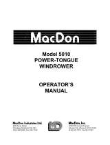
Auger Flighting Extension Installation
Step 2 Place header in a suitable work area
and detach from combine if it is not
already detached.
Step 3 Fasten the flighting extensions to the
the existing auger flighting using two
(2) M8 x 25 button head capscrews,
four (4) flat washers, two (2) lock
washers and two (2) nuts per extension.
Be sure there is a flat washer under the
bolt heads and under the lock washers.
Be sure the mounting flange on the
extension is located on the outboard
side of the existing auger flighting.
Step 4 Remove hand-hole covers as required.
Fasten the flighting extensions to the
auger tube using M8 carriage bolts, flat
washers, lock washers and nuts.
Auger Flighting Extension Installation
D00415

COMPLETION KIT INSTRUCTIONS
Form 169221 Rev. C
6
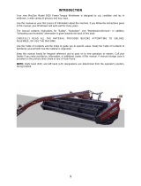
Auger Finger Installation
Step 5 Locate the four covered finger hole
locations in the auger (A through D
shown below).
Remove hand-hole covers as required
for access. At locations A, B, C and D,
remove finger hole covers and install
auger fingers, guides and pins as shown
at right using two (2) M6 x 20 hex head
bolts, four (4) flat washers and two (2)
lock nuts per guide. Be sure there is a
flat washer under the bolt heads and
under the lock nuts.
Auger Finger Installation
Step 6 Rotate the auger by hand so that the
finger being installed is in a workable
area.
CAUTION: When rotating the
auger be sure all people and tools
are clear.
Step 7 Place the hand-hole covers removed
previously back into position and
secure with the M6 hardware.
D00236
/