Page is loading ...

The harvesting specialists.
A30-D and A40-D
Pull-Type Mower Conditioners and
Self-Propelled Windrower Auger
Headers
Operator’s Manual
147675 Revision A
2016 Model Year
Original Instruction

MacDon A40-D Self-Propelled Auger Header and A30-D Pull-Type Mower Conditioner
Pub
lished: May, 2015

Introduction
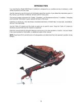
This Operator ’s Manual describes the operating and maintenance procedures for MacDon model A30-D Pull-Type
Mower Conditioners and A40-D Self-Propelled Auger Headers, including a Grass Seed version.
These auger headers are designed to cut, condition, and lay windrows in a wide variety of grasses and hay crops.
The double-knife feature expands the operational envelope, especially in heavier crops.
Model Description
Configuration Knife Size (ft.)
Features
A30-D
Mower
conditione
r
Pull-type Double 14, 16, and 18 Mechanicald
rive
A40-D
Auger header
with conditioner
Self-propelled
only
Double 14, 16, and 18
Separate
hydraulic auger,
knife, and reel
drives, grass
seed option
Use this manual as your first source of information about the machine. Use the Table of Contents and the Index to
guide you to specific topics. Study the Table ofCo nten ts to familiarize yourself with how the information is o rg a niz ed .
If you follow the instructions provided here, your header will work well for many years.
Keep this manual handy for frequent reference, and to pass on to new Operators or Owners. Contact your Dealer
if you need assistance, information, or additional copies of this manual.
CAREFULLY READ THE INFOR MATION PROVIDED IN THIS MANUAL BEFORE ATTEMPTING TO OPERATE
OR MAINTAIN AN A30-D MOWER CONDITIONER OR AN A40-D AUGER HEADER.
NOTE:
Keep yo
ur MacDon publications up-to-date. The most current version can be downloaded from our website
(www.m
acdon.com) or from our Dealer-only site (https://portal.macdon.com) (login required).
NOTE:
A Russian translation of this manual can be ordered from MacDon, downloaded from the MacDon Dealer
Portal (https://portal.macdon.com) (login required), or downloaded from the MacDon international website
(http://www.macdon.com/world).
147675
i
Revision A

Model and Serial Number
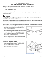
Record the model number, serial number, and model year
of the header and the articulated power turn (APT) in the
space below. The header serial number plate is located on
the top of the left-hand end frame (A).
Header Model Number: ____________
Header Serial Number: ____________
Year: ______
(If 2015, indicate early-build or later-build unit:
______________)
NOTE:
Early-build 2015 model A40-D SP windrower headers
have a round reel motor (as do 2014 and earlier
model year units). Later-build 2015 models have a
square-shaped reel motor. For a visual, refer to 2.2.2
A40-D, page 27 .
Figure 1: Header Serial N umber Plate Location
APT Serial Number (Pull-Type):
___________________________________________
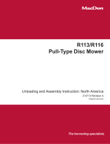
The APT Serial Number plate is located at the top aft end
of the APT (A).
PTO Speed:
• 540 rpm [____]
• 1000 r pm [____]
Figure 2: APT
Serial Number Plate Location
147675
i
i
Revision A

List of Revisions
The following
list provides an account of major changes from the previous version of this document.
Summary of Cha
nge
Location
Removed EC Declaration of
Conformity
Updated safety sign (decal) location
illustration
1 Safety, page 1
Revised Pr
oduct Specifications
2.3 Produc
tSpecifications, page 29
Added Product Overview chapter 2 Product Overview, page 23
Updated Setting Up Drawbar Hitch
illustrations
3.1.3 Setting Up Drawbar Hitch, page 34
Added Se
tting Knife Speed section to
A30-D op
erating variables
3.7.2 Se
tting Knife Speed , page 57
Updated factory setting information for
reel fore-aft position for A30-D
Setting Reel Fore-Aft Position, page 68
Updated factory setting information for
reel vertical position for A30-D
Setting Reel Vertical Position, page 69
Upda
ted float setting information for
A30-
D
3.7.
10 Setting Float, page 76
Updated conditioner roll gap factory
settings for A30-D
3.7.12 Adjusting Conditioner Roll Gap, page 77
Updated conditioner roll gap factory
settings for A40-D
4.5.10 Adjusting Conditioner Roll Gap, page 147
Up
dated factory settings and
ad
ded new illu stration for adjusting
co
nditioner roll tension for A30-D
3.
7.13 Adjusting Conditioner Roll Tension, page 78
Updated factory settings and
added ne w illustration for adjusting
conditioner roll tension for A40-D
4.5.11 Adjusting Conditioner Roll Tension, page 148
Updated factory setting information for
reel fore-aft position for A40-D
Adjusting Reel Fore-Aft Position, page 141
Updated factory setting information for
reel vertical position for A40-D
Adjusting Reel Vertical Position, page 142
Added information on unplugging
self-propelled header if reverser is
installed on windrower
4.7 Unplugging Conditioner and Knife: Self-Propelled, page 155
Checking knife hold-downs added
to daily maintenance checklist for
pull-type headers
6.4.1 Maintenance Schedule/Record: Pull-Type, page 171
Checking knife hold-downs added
to daily maintenance checklist for
self-propelled headers
6.4.2 Maintenance Schedule/Record: Self-Propelled, page 173
147675
i
ii
Revision A


TABLE OF CONTENT
S
Introduction...................................................................................................................................... i
Model and Serial Number.................................................................................................................. ii
List of Revisions ..............................................................................................................................iii
1 Safety.................................................................................................................................................... 1
1.1 Safety Alert Symbols........................................................................................................................ 1
1.2 Signal Words................................................................................................................................... 2
1.3 General Safety ................................................................................................................................ 3
1.4 Maintenance Safety......................................................................................................................... 5
1.5 Hydraulic Safety .............................................................................................................................. 6
1.6 Tire Safety....................................................................................................................................... 7
1.7 Safety Signs.................................................................................................................................... 8
1.7.1 Installing Safety Deca ls ............................................................................................................ 8
1.8 Safety Sign Locations: Pull Type Mower Coditioner ........................................................................... 9
1.9 Safety Sign Locations: Self-Propelled Windrower Header................................................................. 12
1.10 Understanding Safety Signs........................................................................................................... 14
1.11 Owner/Operator Re sp o ns ibilities..................................................................................................... 21
1.12 Operational Safety......................................................................................................................... 22
2 Product Overview................................................................................................................................23
2.1 Definitions..................................................................................................................................... 23
2.2 Model Identification........................................................................................................................ 25
2.2.1 A30-D .................................................................................................................................... 26
2.2.2 A40-D .................................................................................................................................... 27
2.3 Product Specifications.................................................................................................................... 29
3 Operation: A30-D Pull-Type Mower Conditioner.................................................................................. 33
3.1 Preparing Tractor for Mower Conditioner......................................................................................... 33
3.1.1 Tractor Requirements............................................................................................................. 33
3.1.2 Adjusting Drawbar.................................................................................................................. 33
3.1.3 Setting Up Drawbar Hitch ....................................................................................................... 34
3.1.4 Installing Three-Point Hitch Yoke (Cat. II, III, or IIIN)................................................................. 35
3.2 Attaching Mower Conditioner to Tractor...........................................................................................37
3.2.1 Attaching Drawbar.................................................................................................................. 37
3.2.2 Attaching Three-Point Hitch (Cat. II, III, or IIIN) ........................................................................ 38
3.2.3 Connecting Hydraulics ............................................................................................................ 41
3.3 Detaching Mower Conditioner from Tractor...................................................................................... 43
3.3.1 Unhooking Drawbar ................................................................................................................ 43
3.3.2 Unhooking Three-Point Hitch..................................................................................................45
3.4 Engaging the Power Take-Off (PTO)............................................................................................... 48
3.5 Lift Cylinder Lock-Outs................................................................................................................... 49
3.6 Steering the Pull-Type Mower Conditioner....................................................................................... 50
3.6.1 Right-Side Operation.............................................................................................................. 51
3.6.2 Left-Side Operation................................................................................................................ 52
3.6.3 Avoiding Obstacles................................................................................................................. 53
3.6.4 Turning Square Corners ......................................................................................................... 54
3.6.5 Turning 180 Degrees.............................................................................................................. 54
3.7 Operating Variables for A30-D........................................................................................................ 56
3.7.1 Setting Lean Bar .................................................................................................................... 57
3.7.2 Setting Knife Speed ............................................................................................................... 57
3.7.3 Setting Auger Speed .............................................................................................................. 60
3.7.4 Setting Reel Speed ................................................................................................................ 61
3.7.5 Setting Auger Position............................................................................................................ 62
Setting Auger Fore-Aft Position ........................................................................................ 62
Setting Auger Vertical Position......................................................................................... 65
3.7.6 Setting Reel Position.......................................................................................................
....... 67
147675
v
Revision A

TABLE OF CONTENT
S
Setting Reel Fore-Aft Position.......................................................................................... 68
Setting Reel Vertical Position........................................................................................... 69
Checking Reel Tine to Header Pan Clearance.................................................................. 72
3.7.7 Setting Cutting Height............................................................................................................. 72
3.7.8 Setting Tine Aggressiveness................................................................................................... 73
3.7.9 Setting Header Angle ............................................................................................................. 74
Mechanically Adjusting Header Angle .............................................................................. 75
Hydraulically Adjusting Header Angle............................................................................... 75
3.7.10 Setting Float .......................................................................................................................... 76
3.7.11 Setting Feed Pan and Rock Drop Tine Position........................................................................ 77
3.7.12 Adjusting Conditioner Roll Gap................................................................................................ 77
3.7.13 Adjusting Conditioner Roll Tension .......................................................................................... 78
3.7.14 Positioning the Forming Shields ..............................................................................................80
Positioning Side Deflectors.............................................................................................. 80
Positioning Rear Deflector (Fluffer Shield)........................................................................ 81
3.8 Recommended Operating Settings .................................................................................................83
3.9 Transporting the A30-D Mower Conditioner..................................................................................... 85
3.9.1 Towing A30-D Mower Conditioner ........................................................................................... 85
Preparing A30-D for Transport......................................................................................... 85
Towing A30-D with a Tractor............................................................................................ 87
Towing A30-D with a Truck.............................................................................................. 88
3.9.2 Transporting A30-D on a Flatbed Trailer .................................................................................. 89
Loading Mower Conditioner on Flatbed Trailer.................................................................. 89
Unloading Mower Conditioner from Flatbed Trailer............................................................ 95
3.10 Unplugging Conditioner and Knife: Pull-Type .................................................................................. 101
4 Operation: A40-D Self-Propelled Windrower Auger Header............................................................... 103
4.1 Attaching A40-D Header to SP Windrower......................................................................................103
4.1.1 Attaching to M100 or M105....................................................................................................103
4.1.2 Attaching to M150, M155, or M155E4.....................................................................................108
4.1.3 Attaching to M200.................................................................................................................113
4.1.4 Attaching to M205.................................................................................................................118
4.1.5 Configuring Reverser Valve Jumper Hose............................................................................... 123
4.1.6 Hydraulic Drive Hose Routing (Early-Build 2015, 2014 and Earlier A40-D for use on M100,
M105 and M205 Windrowers Only) .................................................................................... 124
4.1.7 Hydraulic Drive Hose Routing (Later-Build 2015 A40-D Units Only).......................................... 126
4.2 Detaching A40-D Header from Windrower......................................................................................131
4.3 Transporting A40-D Header with Windrower...................................................................................135
4.4 Lift Cylinder Lock-Outs: Self-Propelled...........................................................................................136
4.5 Operating Variables for A40-D.......................................................................................................137
4.5.1 Setting Lean Bar ................................................................................................................... 138
4.5.2 Adjusting Auger Speed..........................................................................................................138
4.5.3 Adjusting Reel Speed............................................................................................................ 138
4.5.4 Setting Auger Position...........................................................................................................138
Adjusting Auger Fore-Aft Position ...................................................................................139
Adjusting Vertical Position.............................................................................................. 140
4.5.5 Setting Reel Position.............................................................................................................141
Adjusting Reel Fore-Aft Position .....................................................................................141
Adjusting Reel Vertical Position ......................................................................................142
Checking Reel Tine to Header Pan Clearance.................................................................144
4.5.6 Setting Tine Aggressiveness..................................................................................................145
4.5.7 Adjusting Header Angle of A40-D........................................................................................... 146
4.5.8 Setting Cutting Height............................................................................................................146
4.5.9 Checking/Adjusting Float.......................................................................................................147
4.5.10 Adjusting Conditioner Roll Gap...............................................................................................147
147675
v
i
Revision A

TABLE OF CONTENT
S
4.5.11 Adjusting Conditioner Roll Tension .........................................................................................148
4.5.12 Positioning the Forming Shields .............................................................................................150
Positionin g Side Deflectors — Self-Propelled................................................................... 150
Positioning Rear Deflector (Fluffer Shield)....................................................................... 151
4.6 Recommended Operating Settings ................................................................................................153
4.7 Unplugging Conditioner and Knife: Self-Propelled........................................................................... 155
4.8 Grass Seed Special A40-D ............................................................................................................156
4.8.1 Stub Guards and Hold-Downs................................................................................................ 156
4.8.2 Special Auger Design for Grass Seed Special A40-D ..............................................................156
4.8.3 Seven-Bat Reel .....................................................................................................................157
4.8.4 Auger Pan Extensions........................................................................................................... 157
Adjusting Pan Extensions: Grass Seed Special............................................................... 158
4.8.5 Windrow Forming Rods .........................................................................................................159
5 Operation: M ower Conditioner and Self-Propelled Auger Header...................................................... 161
5.1 Selecting Ground Speed ...............................................................................................................161
5.2 Tall Crop Dividers .........................................................................................................................162
5.2.1 Adjusting Tall Crop Dividers ................................................................................................... 162
5.2.2 Removing Tall Crop Dividers..................................................................................................163
5.3 Haying.........................................................................................................................................165
5.3.1 Haying Tips........................................................................................................................... 165
Curing...........................................................................................................................165
Topsoil Moisture............................................................................................................. 165
Weather and Topography...............................................................................................165
Windrow Characteristics................................................................................................. 165
Driving on Windrow........................................................................................................166
Raking and Tedding....................................................................................................... 166
Using Chemical Drying Agents ....................................................................................... 166
6 Mainten
ance and Servicing................................................................................................................167
6.1 Prepar
ing for Servicing..................................................................................................................167
6.2 Drives
hields .................................................................................................................................168
6.3 Mainte
nance Specifications........................................................................................................... 169
6.3.1 Recomm
ended Fluids and Lubricants.....................................................................................169
6.4 Mainte
nance Requirements...........................................................................................................170
6.4.1 Maint
enance Schedule/Record: Pull-Type ..............................................................................171
6.4.2 Maint
enance Schedule/Record: Self-Propelled .......................................................................173
6.4.3 Break
-In Inspection: Pull-Type ............................................................................................... 175
6.4.4 Break
-In Inspection: Self-Propelled........................................................................................ 175
6.4.5 Prese
ason Checks................................................................................................................176
6.4.
6
Stor
age ................................................................................................................................176
6.5 Lubr
ication...................................................................................................................................178
6.5.
1
Grea
sing Procedure .............................................................................................................. 178
6.5.
2
Lubr
ication Points..................................................................................................................179
Lubr
ication Points: A30-D Mower Conditioners................................................................180
Lubr
ication Points: A40-D SP Windrower Headers........................................................... 182
Lub
rication Points: Hay Conditioner................................................................................ 184
Lub
rication Points: Drivelines .........................................................................................185
Lub
rication Points: Pull-Type Carrier Frame ....................................................................186
6.5
.3
Oil
ing ....................................................................................................................................187
6.5
.4
Ins
talling Sealed Bearin g s
......................................................................................................188
6.
6
Hy
d
raulics....................................................................................................................................189
6.
6.1
Se
rvicing A40-D Hydraulics.................................................................................................... 189
6.
6.2
Se
rvicing A30-D Hydraulics.................................................................................................... 189
Ch
ecking Hydraulic Oil Level.......................................................................................... 189
147675
v
ii
Revision A

TABLE OF CONTENT
S
Adding Hydraulic Oil ......................................................................................................190
Changing Hydraulic Oil – Articulated Hitch....................................................................... 190
Changing Hydraulic Oil Filter ..........................................................................................191
Checking Pressure Relief Valve...................................................................................... 192
6.6.3 Checking Hoses and Lines .................................................................................................... 192
6.7 Cutterbar......................................................................................................................................193
6.7.1 Replacing Knife Section.........................................................................................................193
6.7.2 Removing Knife .....................................................................................................................193
6.7.3 Installing Knife ...................................................................................................................... 194
6.7.4 Removing Knifehead Bearing................................................................................................. 195
6.7.5 Installing K nifehead Bearing...................................................................................................196
6.7.6 Removing Spare Knife from Storage....................................................................................... 196
6.7.7 Guards.................................................................................................................................197
Aligning Guard............................................................................................................... 199
Replacing Pointed Guards and Hold-Downs....................................................................200
Replacing Pointed Center Guard on Double-Knife Header ................................................ 202
Replacing Center Stub Guard on Double-Knife Header.................................................... 204
6.7.8 Hold-Downs..........................................................................................................................206
Adjusting Knife Hold-Down: Pointed Guard – Double-Knife Header/Mower
Conditioner................................................................................................................ 207
Adjusting Center Knife Hold-Down: Stub Guard – Double-Knife Header............................207
6.7.9 Knife Drive Box.....................................................................................................................208
Mounting Bolts...............................................................................................................208
Removing Knife Drive Box ..............................................................................................209
Installing Knife Drive Box................................................................................................ 210
Removing Pulley............................................................................................................212
Installing Pulley .............................................................................................................212
Changing Knife Drive Box Oil .........................................................................................213
6.7.10 Adjusting Knife Timing........................................................................................................... 213
6.8 A30-D Drive Systems ....................................................................................................................216
6.8.1 Knife Drive – A30-D...............................................................................................................216
Checking/Adjusting Timing Belt Tension on Left Side – A30-D ..........................................216
Removing Timing Belt – A30-D Left Side......................................................................... 216
Installing Timing Belt – A30-D Left Side........................................................................... 217
Checking/Adjusting V-Belts Tension on Left Side – A30-D ................................................ 219
Removing Double V-Belts – A30-D Left Side ...................................................................219
Installing Double V-Belts – A30-D Left Sid e ..................................................................... 220
Checking/Adjusting Timing Belt Tension on Right Side .....................................................220
Removing Timing Belt – A30-D Right Side.......................................................................221
Installing Timing Belt – A30-D Right Side.........................................................................222
6.8.2 Reel Drive – A30-D ...............................................................................................................223
Checking/Adjusting Reel Drive Chain Tension – A30-D ....................................................223
Removing Reel Drive Chain – A30-D ..............................................................................224
Installing Reel Drive Chain – A3 0-D ................................................................................ 224
Checking/Adjusting Reel Drive Belt Tension..................................................................... 224
Removing Reel Drive Belt ..............................................................................................225
Installing Reel Drive Belt ................................................................................................226
6.8.3 Auger Drive – A30-D ............................................................................................................. 226
Checking/Adjusting Auger Drive Chain Tension – A30-D .................................................. 226
Removing Auger Drive Chain ......................................................................................... 227
Installing Auger Drive C ha in ...........................................................................................227
6.9 A40-D Drive Systems ....................................................................................................................228
6.9.1 Knife Drive – A40-D...............................................................................................................228
Checking/Adjusting V-Belt Tension on Left Side – A40-D..................................................228
147675
v
iii
Revision A

TABLE OF CONTENT
S
Removing Double V-Belts on Left Side – A40-D...............................................................228
Installing Doub le V-Belts – A40-D Left Side .....................................................................229
Checking/Adjusting Timing Belt Tension – A40-D Left Side...............................................229
Removing Timing Belt on Left Side ................................................................................. 230
Installing Timing Belt - A40-D Left Side............................................................................ 232
Checking/Adjusting Timing Belt Tension on Right Side ..................................................... 233
Removing Timing Belt – A40-D Right Side ....................................................................... 233
Installing Timing Belt – A40-D Right Side......................................................................... 234
6.9.2 Reel Drive – A40-D ...............................................................................................................235
6.9.3 Auger Drive – A40-D ............................................................................................................. 235
6.10 Reel Tines and Tine Bar Bearings................................................................................................. .236
6.10.1 Reel Tines and Tine Bar Bearings – A30-D.............................................................................236
Removing Tines and Bearings – A30-D: Cam End .......................................................... 236
Removing Tines and Bearings – A30-D: Opposite Cam End.............................................237
Installing Tines and Bearings – A30-D: Opposite Ca m E n d............................................... 237
6.10.2 Reel Tines and Tine Bar Bearings – A40-D.............................................................................238
Replacing Tine and Bearing – A40-D: Cam End – Disc #1................................................ 238
Replacing Tine and Bearing – A40-D: Disc #2.................................................................. 243
Replacing Tine and Bearing – A40-D: Center Section X ...................................................246
Replacing Tine and Bearing – A40-D: Opposite Cam – Section Y ..................................... 248
Replacing Tine – A40-D: Tine Bar Extension – Section Z .................................................. 250
6.11 Auger Drive – A30-D.....................................................................................................................252
6.11.1 Straightening Auger Pans – A30-D.........................................................................................252
6.11.2 Replacing Rubber Fingers – A30-D........................................................................................ 252
6.11.3 Stripper Bar..........................................................................................................................253
Removing Stripper Bar................................................................................................... 253
Replacing Stripper Bars ................................................................................................. 253
Installing Front Stripper Bar Ex te ns ion s...........................................................................254
6.12 Conditioner...................................................................................................................................256
6.12.1 Changing Gearbox Oil...........................................................................................................256
6.12.2 Removing Forming Shield (A40-D)......................................................................................... 258
6.12.3 Disassembling Forming Shield (A40-D) ..................................................................................259
6.12.4 Assembling Forming Shield (A40-D)....................................................................................... 260
6.12.5 Installing Forming Shield (A40-D)........................................................................................... 262
6.12.6 Removing Header Drive Motor: A30-D, A40-D........................................................................264
6.12.7 Installing Header Drive Motor: A30-D, A40-D.......................................................................... 265
6.12.8 Removing Conditioner Gearbox – A30-D................................................................................ 265
6.12.9 Installing Conditioner Gearbox – A30 -D .................................................................................. 268
6.12.10 Removing Conditioner Gearbox – A40-D ................................................................................271
6.12.11 Installing Conditione r Ge a rbox – A4 0 -D ..................................................................................274
6.12.12 Checking/Adjusting Roll Alignment.........................................................................................277
6.12.13 Checking/Adjusting Roll Timing..............................................................................................278
6.13 Wheels and Tires .........................................................................................................................281
6.13.1 Checking Wheel Bolts ...........................................................................................................281
6.13.2 Removing Wheel ...................................................................................................................281
6.13.3 Installing Wheel..................................................................................................................... 281
6.13.4 Inflating Tire..........................................................................................................................282
6.14 Replacing Skid Shoe Wear Plate...................................................................................................283
6.15 Gauge Rollers..............................................................................................................................285
6.15.1 Removing Gauge Rollers.......................................................................................................285
6.15.2 Installing Gauge Rollers......................................................................................................... 285
6.16 Maintaining the Electrical System ..................................................................................................287
7 Optional Equipment ...........................................................................................................................289
7.1 Options and Attachments..............................................................................................................289
147675
i
x
Revision A

TABLE OF CONTENT
S
7.1.1 Additional Skid Shoes ............................................................................................................289
7.1.2 Gauge Roller Kit....................................................................................................................289
7.1.3 Hydraulic Header Angle Kits ..................................................................................................290
7.1.4 Replacement Reel Bat Kit......................................................................................................290
7.1.5 Stub Guard Conversion Kit ....................................................................................................290
7.1.6 Tall Crop Divider Kit............................................................................................................... 291
8 Unloading and Assembly...................................................................................................................293
9 Troubleshoo
ting.................................................................................................................................295
9.1 Header/Mo we
r Conditioner Performance ........................................................................................ 295
9.2 Mechanical...................................................................................................................................3
02
10 Reference...........................................................................................................................................305
10.1 Torq ue Specifications.................................................................................................................... 305
10.1.1 SAE Bolt Torque Specifications.............................................................................................. 305
10.1.2 Metric Bolt Specifications....................................................................................................... 307
10.1.3 Metric Bolt Specifications Bolting into Cast Aluminum..............................................................310
10.1.4 Flare-Type Hydraulic Fittings..................................................................................................310
10.1.5 O-Ring Boss (ORB) Hydraulic Fittings (Adjustable).................................................................. 312
10.1.6 O-Ring Boss (ORB) Hydraulic Fittings (Non-Adjustable) ..........................................................314
10.1.7 O-Ring Face Seal (ORFS) Hydraulic Fittings ........................................................................... 315
10.2 Conversion Chart..........................................................................................................................317
Index ..................................................................................................................................................319
147675
x
Revision A

1Safety
1.1 Safety Alert Symbols
This safety alert symbol indicates important safety
messages in this manual and on safety signs on the .
This symbol means:
• ATTENTION!
• BECOME ALERT!
• YOUR SAFETY IS INVOLVED!
Carefully read and follow the safety message
accompanying this symbol.
Why is safety important to you?
• Accidents disable and kill
• Accidents cost
• Accidents can be avoided
Figure 1.
1: Safety Symbol
147675
1
Revision A

SAFETY
1.2 Signal Words
Three signal words, DANGER, WARNING, and CAUTION, are used to alert you to hazardous situations. The
appropriate signal word for each situation has been selected using the following guidelines:
DANGER
Indicates an imminently hazardous situation that, if not avoided, will result in death or serious injury.
WARNING
Indicates a potentially hazardous situation that, if not avoided, could result in death or serious injury. It
may also be used to alert against unsafe practices.
CAUTION
Indicates a potentially hazardous situation that, if not avoided, may result in minor or moderate injury. It
may be used to alert against unsafe practices.
147675
2
Revision A

SAFETY
1.3 General Safety
CAUTION
The following are general farm safety precautions
that should be part of your operating procedure for
all types of machinery.
Protect yourself.
• When assembling, operating, and servicing machinery,
wear all the protective clothing and personal safety
devices that could be necessary for the job at hand.
Don’t take chances. You may need the following:
• Hard hat
• Protective footwear with slip resistant soles
• Protective glasses or goggles
• Heavy gloves
• Wet weather gear
• Respirator or filter mask
Figure 1.2
: Safety Equipment
• Be aware that exposure to loud noises can cause
hearing impairment or loss. Wear suitable hearing
protection devices such as ear muffs or ear plugs to
help protect against objectionable or loud noises.
Figure 1.3: Safety Equipment
•Provideafirst aid kit for use in case of emergencies.
• Keep a fire extinguisher on the mach ine. Be sure the
fire extinguisher is pro perly maintained. Be familiar with
its prope r use.
• Keep young children away from the machinery at
all times.
• Be aware that accidents often happen when the
Operator is tired or in a h u rry. Take the time to
consider the s afest way. Nev er ig nore the warning
signs of fatigue .
Figure 1.4: Safety Equipment
147675 3 Revision A

SAFETY
•Wearclose-fitting clothing and cover long hair. Never
wear dangling items such as scarves or bracelets.
• Keep all shields in place. Never alter or remove safety
equipment. Make sure driveline guards can rotate
independently of the shaft and can telescope freely.
• Use only service and repair parts made or approved by
the equipment manufacturer. Substituted parts may not
meet strength, design, or safety requirements.
Figure 1.5: Safety Around Equipment
• Keep hands, feet, clothing, and hair away from moving
parts. Never attempt to clear obstructions or objects
from a machine while the engine is running.
•DoNOT modify the machine. Non-authorized
modifications may impair machine function and/or
safety. It may also shorten the machine’s life.
• To avoid bodily injury or death from unexpected startup
of machine, always stop engine and remove key from
ignition before leaving operator’s seat for any reason.
Figure 1.6: Safety Around Equipment
• Keep the service area clean and dry. Wet or oily floors
areslippery. Wet spots canbe dangerouswhen working
with electrical equipment. Be sure all electrical outlets
and tools are properly grounded.
• Keep work area well lit.
• Keep machinery clean. Straw and chaff on a hot
engine is a fire hazard. Do NOT allow oil or grease to
accumulate on service platf orms, ladders, or controls.
Clean machines before storage.
• Never use gasoline, naphtha, or any volatile material
for cleaning purposes. These materials may be toxic
and/or flammable.
• When storing machinery, cover sharp or extending
components to p revent injury from accidental contact.
Figure 1.7: Safety Around Equipment
147675
4
Revision A

SAFETY
1.4 Maintenance Safety
To ensure your safety while maintaining the machine:
• Review the operator’s manual and all safety items
before operation and/or maintenance of the machine.
• Place all controls in Neutral, stop the engine, set
the park brake, remove the ignition key, and wait for
all moving parts to stop before servicing, adjusting,
and/or repairing.
• Follow good shop practices:
– Keep service areas clean and dry
– Be sure electrical outlets and tools are
properly grounded
– Use adequate lighting for the job at hand
Figure 1.8: Safety Around Equipment
• Relievepressure fromhydraulic circuits beforeservicing
and/or disconnecting the machine.
• Make sure all components are tight and that steel lines,
hoses, and couplings are in good condition before
applying pressure to hydraulic systems.
• Keep hands, feet, clothing, and hair away from all
moving and/or rotating parts.
• Clear the area of bystanders, especially children, when
carrying out any maintenance, repairs or, adjustments.
• Install transport lock or place safety stands under the
frame before working under the .
• If more than one person is servicing the machine at the
same time, be aware that rotating a driveline or other
mechanically-driven component by hand (for example,
accessing a lube fitting) will cause drive components in
other areas (belts, pulleys, and knives) to move. Stay
clear of driven components at all tim es.
Figure 1.9: Eq
uipment NOT Safe for Children
• Wear protective gea
r when working on the machine.
• Wear heavy gloves w
hen working on knife components.
Figure 1.10: Saf
ety Equipment
147675 5 Revision A

SAFETY
1.5 Hydraulic Safety
• Always place all hydraulic controls in Neutral
before dismounting.
• Make sure that all components in the hydraulic system
are kept clean and in good condition.
• Replace any worn, cut, abraded, flattened, or crimped
hoses and steel lines.
•DoNOT attempt any makeshift repairs to the hydraulic
lines, fittings,orhoses by usingtapes, clamps,cements,
or welding. The hydraulic system operates under
extremely high pressure. Makeshift repairs will fail
suddenly and create hazardous and unsafe conditions.
Figure 1.11: Testing for Hydraulic Leaks
•Wearprope
r hand and eye protection when searching
for high-p
ressure hydraulic leaks. Use a piece of
cardboar
d as a backstop instead of hands to isolate
and ident
ify a leak.
•Ifinjure
d by a concentrated high-pressure stream of
hydrauli
c fluid, seek medical attention immediately.
Serious
infection or toxic reaction ca n develop from
hydraul
ic fluid piercing the skin.
Figure
1.12: Hydraulic Pressure Hazard
• Make sure all components are tight and steel lines,
hoses, and couplings are in good condition before
applying pressure to a hydraulic system.
Figure 1.13: Safety Around Equipment
147675 6 Revision A

SAFETY
1.6 Tire Safety
• Follow proper procedures w hen mounting a tire on a
wheel or rim. Failure to do so can produce an explosion
that may result in serious injury or death.
Figure 1.14: Overinflated Tire
•DoNOT atte
mpt to mount a tire unless you have the
proper tra
ining and equipment.
• Haveaqua
lified tire dealer or repair service perform
required
tire maintenance.
Figure 1.15: S afely Filli ng a Tire with Air
147675
7
Revision A

SAFETY
1.7 Safety Signs
• Keep safety signs clean and legible at all times.
• Replace safety signs that are missing or
become illegible.
• If original parts on which a safety sign was installed are
replaced, be sure the repair part also bears the current
safety sign.
• Safety signs are available from your Dealer
Parts Department.
Figure 1.16: Operator’s Manual Decal
1.7.1 Installing Safety Decals
1. Clean and
dry the installation area.
2. Decide on
the exact location before you remove the decal backing paper.
3. Remove th
e smaller portion of the split backing paper.
4. Place th
e sign in p osition and slowly peel ba c k the remaining paper, smoothing the sign as it is app lied.
5. Prick sm
all air pockets with a pin and smooth out.
147675 8 Revision A
/