Page is loading ...

CommerCommer
CommerCommer
Commer
cialcial
cialcial
cial
DirDir
DirDir
Dir
ect Gear Driect Gear Dri
ect Gear Driect Gear Dri
ect Gear Dri
vv
vv
v
ee
ee
e
Bin SwBin Sw
Bin SwBin Sw
Bin Sw
eeee
eeee
ee
p p
p p
p
AA
AA
A
ugug
ugug
ug
erer
erer
er
AssembAssemb
AssembAssemb
Assemb
ll
ll
l
y &y &
y &y &
y &
OperOper
OperOper
Oper
aa
aa
a
tion Mantion Man
tion Mantion Man
tion Man
ualual
ualual
ual
PNEG-1521
Date: 10-25-2007
PNEG-1521

2 PNEG-1521 Commercial Direct Gear Drive Bin Sweep Auger
36' CPS10360
42' CPS10420
48' CPS10480
54' CPS10540
60' CPS10600
72' CPS10720
75' CPS10750
78' CPS10780
Bin Dia.
10" Commercial
DGD Sweep
This manual is valid for the sweep catalog numbers in the table below.

3PNEG-1521 Commercial Direct Gear Drive Bin Sweep Auger
TABLE OF CONTENTS
Introduction..........................................................................................................................4
Safety Guidelines ................................................................................................................5
Safety Instructions............................................................................................................6-8
Operator Qualifications .......................................................................................................9
Decals..........................................................................................................................10-11
Installation Section
Power Sweeps in Bins with Concrete Floors ..........................................................12
Power Sweeps in Bins with Raised Metal Floors ....................................................13
Intermediate Well Installation ...................................................................................14
Unload Tube Assembly Installation .....................................................................15-16
Outer Unload Tube Assembly Installation ...........................................................17-18
Centerwell Control Gate Assembly ..........................................................................19
Bin Flange Installation ..............................................................................................20
Rack & Pinion Installation ...................................................................................21-22
Clutch Control Installation ...................................................................................23-24
Assembling and Installing the Unload Flight........................................................25-26
Installing the Sweep Flighting..............................................................................27-31
Sweep Wheel Installation ...................................................................................32-34
Motor Selection..................................................................................................................35
Before Filling the Bin .........................................................................................................36
Pre-Start Checks...............................................................................................................37
Normal Operation.........................................................................................................38-39
Engaging the Clutch for the Bin Sweep.............................................................................40
Final Clean-Out ............................................................................................................41-42
Shutdown ..........................................................................................................................43
Maintaining the Auger ........................................................................................................44
Troubleshooting............................................................................................................45-46
Parts Section
Parts ...................................................................................................................47-62
Warranty............................................................................................................................63
TABLE OF CONTENTS

4 PNEG-1521 Commercial Direct Gear Drive Bin Sweep Auger
READ THIS MANUAL carefully to learn how to
properly use and install equipment. Failure to do
so could result in personal injury or equipment
damage.
INSPECT the shipment immediately upon arrival.
The Customer is responsible for ensuring that all
quantities are correct. Report any damage or
shortages by recording a detailed description on
the Bill of Lading to justify the Customer’s claim
from the Transport Firm.
THIS MANUAL SHOULD BE CONSIDERED a
permanent part of your equipment and should be
easily accessible when needed.
WARRANTY is provided as part of the company’s
support program for customers who use and
maintain their equipment as described in the
manual. The warranty is explained on the warranty
page located on the inside of the back cover.
This warranty provides you the assurance that the
company will back its products where defects
appear within the warranty period. Should the
equipment be abused, or modified to change its
performance beyond the factory specifications,
the warranty will become void.
INTRODUCTION
INTRODUCTION

SAFETY
5PNEG-1521 Commercial Direct Gear Drive Bin Sweep Auger
This manual contains information that is important for you, the owner/operator, to know and
understand. This information relates to protecting personal safety and preventing equipment
problems. It is the responsibility of the owner/operator to inform anyone operating or working in the
area of this equipment of these safety guidelines. To help you recognize this information, we use the
symbols that are defined below. Please read the manual and pay attention to these sections. Failure
to read this manual and it’s safety instructions is a misuse of the equipment and may lead to serious
injury or death.
DANGER indicates an imminently hazardous situation
which, if not avoided, will result in death or serious injury.
This is the safety alert symbol. It is used to alert you
to potential personal injury hazards. Obey all
safety messages that follow this symbol to avoid
possible injury or death.
WARNING indicates a potentially hazardous situation
which, if not avoided, could result in death or serious injury.
CAUTION indicates a potentially hazardous situation which,
if not avoided, may result in minor or moderate injury.
CAUTION used without the safety alert symbol indicates a
potentially hazardous situation which, if not avoided, may
result in property damage.
NOTE indicates information about the equipment that you
should pay special attention to.
SAFETY GUIDELINES

SAFETY
6 PNEG-1521 Commercial Direct Gear Drive Bin Sweep Auger
GSI’s principle concern is your safety and the safety of others associated with grain handling equipment.
We want to keep you as a customer. This manual is to help you to understand safe operating procedures
and some problems which may be encountered by the operator and other personnel.
As owner and/or operator, it is your responsibility to know what requirements, hazards and precautions
exist, and to inform all personnel associated with the equipment or in the area. Safety precautions may be
required from the personnel. Avoid any alterations to the equipment. Such alterations may produce a very
dangerous situation, where SERIOUS INJURY or DEATH may occur.
This equipment shall be installed in accordance with the current installation codes and applicable
regulations which should be carefully followed in all cases. Authorities having jurisdiction should be
consulted before installations are made.
OPERATE UNLOAD EQUIPMENT PROPERLY
Make sure ALL equipment is locked in position before operating.
NEVER start equipment until ALL persons are clear of the work area.
Be sure all operators are adequately rested and prepared to
perform all functions of operating this equipment.
NEVER allow any person intoxicated or under the influence of alcohol or
drugs to operate the equipment.
NEVER work alone.
Make sure someone is nearby who is aware of the proper shutdown
sequence in the event of an accident or emergency.
ALWAYS think before acting. NEVER act impulsively around the
equipment.
NEVER allow anyone inside a bin, truck or wagon which is being
unloaded by an auger or conveyor. Flowing grain can trap and suffocate
in seconds.
Use ample overhead lighting after sunset to light the work area.
Keep area around intake free of obstacles such as electrical cords,
blocks, etc., that might trip workers.
NEVER drive, stand or walk under the equipment.
Use caution not to hit the auger when positioning the load.
ALWAYS lockout ALL power to the equipment when finished
unloading a bin.
Operate
Unload
Equipment
Safely
SAFETY INSTRUCTIONS

SAFETY
7PNEG-1521 Commercial Direct Gear Drive Bin Sweep Auger
FOLLOW SAFETY INSTRUCTIONS
Carefully read all safety messages in this manual
and on your machine safety signs. Keep signs in
good condition. Replace missing or damaged
safety signs. Be sure new equipment
components and repair parts include the current
safety signs. Replacement safety signs are
available from the manufacturer.
Learn how to operate the machine and how to
use controls properly. Do not let anyone operate
without instruction.
Keep your machinery in proper working
condition. Unauthorized modifications to the
machine may impair the function and/or safety
and affect machine life.
If you do not understand any part of this manual
and need assistance, contact your dealer.
Read and Understand Manual.
INSTALL & OPERATE ELECTRICAL
EQUIPMENT PROPERLY
To avoid serious injury or death, stay away from
unit and make sure everyone is clear of all augers
before starting or operating the unit.
Electrical controls should be installed by a
qualified electrician and must meet the standards
set by the national electrical code and all local and
state codes.
Disconnect and lock out all power sources
before installing wires/cables or servicing
equipment .
Do not operate electric motor equipped units until
motors are properly grounded.
Disconnect power on electrical driven units before
resetting motor overloads.
Do not repetitively stop and start the drive in order
to free a plugged condition. Jogging the drive in
this type of condition can damage the equipment.
Electric Shock Hazard.

SAFETY
8 PNEG-1521 Commercial Direct Gear Drive Bin Sweep Auger
PREPARE FOR EMERGENCIES
Be prepared if fire starts.
Keep a first aid kit and fire extinguisher handy.
Keep emergency numbers for doctors,
ambulance service, hospital, and fire department
near your telephone.
WEAR PROTECTIVE CLOTHING
Wear close fitting clothing and safety equipment
appropriate to the job.
Safety glasses should be worn at all times to
protect eyes from debris.
Wear gloves to protect your hands from sharp
edges on plastic or steel parts.
A respirator may be needed if a hog house has
poor ventilation. Waste fumes can be toxic.
Wear hard hat and steel toe boots to help
protect your head and toes from falling debris.
Remove all jewelry.
Tuck in any loose or dangling shoe strings.
Long hair should be tied up and back.
Eye Protection
Gloves
Steel Toe
Boots
Respirator
Hard Hat
Keep Emergency Equipment
Quickly Accessible.

SAFETY
9PNEG-1521 Commercial Direct Gear Drive Bin Sweep Auger
Date Employees Signature
1
2
3
4
5
6
7
8
9
10
11
12
13
14
15
Employees Name (printed)
A. The User/Operator must be competent and experienced to operate auger equipment. Anyone who
works with or around augers must have good common sense in order to be qualified. These persons
must also know and meet all other qualifications, such as:
1. Any person who has not read and/or does not understand all operation and safety instructions is
not qualified to operate any auger systems.
2. Certain regulations apply to personnel operating power machinery. Personnel under the age of
18 years may not operate power machinery, including augers. It is your responsibility, as owner
and/or supervisor, to know what these regulations are in your area or situation.
3. Unqualified or incompetent persons are to remain out of work area.
4. O.S.H.A. (Occupational Safety & Health Administration) regulations state: “At the time of initial
assignment and at least annually thereafter, the employer shall instruct every employee in the
safe operation and servicing of all equipment with which the employee is, or will be involved”.
(Federal Occupational Safety & Health Standards for Agriculture. Sub part D, Section 19287.57
(a) (6).
B. As a requirement of OSHA, it is necessary for the employer to train the employee in the safe operating
and safety procedures for this auger. We included this sign-off sheet for your convenience and per
sonal record keeping. All unqualified people are to stay out of the work area at all times. It is strongly
recom mended that another qualified person who knows the shutdown procedure is in the area in the
event of an emergency. A person who has not read this manual and understands all operating and
safety instructions, is not qualified to operate the machine.
OPERATOR QUALIFICATIONS.

DECALS
10 PNEG-1521 Commercial Direct Gear Drive Bin Sweep Auger
Check the components shown below to insure that the safety decals are in place and in good condition. If
a decal cannot be easily read for any reason or has been painted over, replace it immediately. Contact
your dealer or the manufacturer to order a replacement decal free of charge.
SAFETY DECALS
Part # Description Size
DC-1266 Danger - Bin Well 7-1/2" x 2-1/2"
DC-1384 Danger - Keep Out Of Bin 6-1/4" x 1-3/4"
DC-1866 Important - Power Sweep Information (? 42' Bin) 7-3/8" x 2-3/4"
DC-1834 Important - Power Sweep Information (36' Bin) 7-3/8" x 2-3/4"
DC-1395 Danger - Rotating Flight 4-1/4" x 6-1/4"
DECAL PART LIST
>
DC-1866
AUGER
TUBE
Outer Rod
Inner Rod
: Control for Inside
Intermediate Well
Gates (Pull To Open)
: Control for Center
Well Gate (Pull to Open)
IMPORTANT:
BEFORE FILLING BIN CLOSE CENTER WELL
AND INTERMEDIATE WELL GATES. POSITION SWEEP
AUGER OVER INTERMEDIATE WELLS.
INSTRUCTIONS:
1. BE SURE POWER SWEEP CLUTCH CONTROL IS
DISENGAGED AND TIGHTEN SET SCREW.
2. START UNLOADING AUGER. OPEN CENTER WELL GATE.
3. WHEN GRAIN STOPS FLOWING FROM CENTER WELL
GATE, OPEN INSIDE INTERMEDIATE WELLS BEFORE
OPENING OUTSIDE INTERMEDIATE WELLS.
4. WHEN GRAIN STOPS FLOWING FROM OUTSIDE
INTERMEDIATE WELLS, STOP AUGER. TO ENGAGE
POWER SWEEP, ROTATE UNLOADING AUGER SLOWLY
UNTIL CLUTCH ENGAGES AND TIGHTEN SET SCREW.
START AUGER.
Control For Outside Intermediate
Well Gates (Pull To Open)
Power Sweep Clutch Control
(Pull To Engage Power Sweep)
DC-1866
DC-1266
• KEEP OUT OF BIN DURING UNLOADING
OPERATIONS.
• WHEN BIN WELLS ARE IN OPEN POSITION
CONVEYING MECHANISM IS NOT COVERED.
FAILURE TO HEED WILL RESULT IN
SERIOUS INJURY OR DEATH!
DC-1266
DC-1384
KEEP OUT OF BIN WHILE SWEEP IS IN OPERATION
RAPIDLY TRAVELING SWEEP AUGER
FAILURE TO HEED WILL RESULT IN
SERIOUS INJURY OR DEATH
DC-1384

DECALS
11PNEG-1521 Commercial Direct Gear Drive Bin Sweep Auger
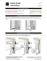
DANGER Decal No. DC-1395 was supplied with your Bin Unloading equipment. This safety sign should
be applied to the side of the bin near the bin opening, so it will be viewed by people entering into the bin
storage building. Do not cover any safety signs or any other signs that are already present.
DC-1384
Located on the back
of the Flight Shield.
SAFETY DECALS
Please remember, safety signs provide important safety information for
people working near bin unloading equipment that is in operation.
KEEP OUT OF BIN WHILE SWEEP IS IN OPERATION
RAPIDLY TRAVELING SWEEP AUGER
FAILURE TO HEED WILL RESULT IN
SERIOUS INJURY OR DEATH
DC-1384
If the Safety Sign cannot be easily read for any reason or has been painted
over, replace it immediately. Additional Safety Signs may be obtained free of
charge from your dealer, distributor, or ordered from the factory.
DC-1395
THIS BIN IS EQUIPPED WITH GRAIN AUGERS
WHICH CAN KILL OR DISMEMBER.
ROTATING FLIGHTING!
KEEP CLEAR OF ALL AUGERS AND NEVER ENTER
THIS BIN UNLESS ALL POWER IS
DISCONNECTED AND LOCKED OUT.
FAILURE TO DO SO WILL RESULT IN
SERIOUS INJURY OR DEATH!
DC-1395

INSTALLATION
12 PNEG-1521 Commercial Direct Gear Drive Bin Sweep Auger
FIG. 1- A FLOOR VIEW
The company does not recommend setting the Direct Gear Drive Bin Sweep
unit in concrete. If installing a unit flush with a concrete floor, we recommend
the unit be installed in a preformed trench. Use the diagram below.
1. POWER SWEEPS IN BINS WITH CONCRETE FLOORS
Center of Bin
TOP VIEW
SIDE VIEW
CONCRETE TRENCH LAYOUT

INSTALLATION
13PNEG-1521 Commercial Direct Gear Drive Bin Sweep Auger
For bins with raised metal floors, it is necessary to cut openings in the floor for the Centerwell and
Intermediate Wells.
A. Make sure the metal floor is high enough above the concrete base so there is space for the wells. It
would be convenient to complete assembly of the bin floor as the power sweep is being installed for
better access to components under the floor.
B. Locate the center of the bin and make a cut-out in the bin floor for the Centerwell.
2. POWER SWEEPS IN BINS WITH RAISED METAL FLOORS
CENTERWELL CUT-OUT AND LOCATION
C. Place the Centerwell into position, with the vertical shaft between the two halves of the gearbox at the
center of the bin. Place suitable supports under the Centerwell to hold it in position.
Center
of Bin
FIG. 2-A CENTER CUT

INSTALLATION
14 PNEG-1521 Commercial Direct Gear Drive Bin Sweep Auger
A. Cut openings in the bin floor for the Intermediate wells. (See figure below.) The number of wells
depends on bin size. The distance between Intermediate wells and the Centerwell should be equal.
3. INTERMEDIATE WELL INSTALLATION
36' 3 17' 10-7/8" 36.363'' 53.75'' 250.888'' 36.013''
42' 4 20' 10-11/16" 32.613'' 50.00'' 286.638'' 35.950''
48' 4 23' 10-1/2" 39.863'' 57.25'' 322.388'' 35.888''
54' 4 26' 10-1/4" 47.113'' 64.50'' 358.388'' 36.138''
60' 5 29' 10-1/8" 42.363'' 59.75'' 394.138'' 36.013''
72' 6 35' 9-3/4" 44.113'' 61.50'' 465.638'' 35.888''
75' 6 37' 3-5/8" 46.613'' 64.00'' 483.638'' 36.013''
78' 6 38' 9-9/16" 49.113'' 66.50'' 501.638'' 36.075''
DISTANCE
FROM CENTER
OF BIN TO
WALL (A)
NUMBER OF
INTERMEDIATE
WELLS
BIN SIZE
DISTANCE
FROM BIN
WALL TO
ANGLE RING
DISTANCE
FROM CENTER
OF BIN TO
ANGLE RING (D)
DISTANCE
BETWEEN
WELLS (C)
DISTANCE BETWEEN
CENTERWELL AND
FIRST INTERMEDIATE
WELL (B)
FIG. 3-A INT-WELLS
INTERMEDIATE WELL LOCATION AND CUT-OUT
FIG. 3-B SIDE VIEW DISTANCE

INSTALLATION
15PNEG-1521 Commercial Direct Gear Drive Bin Sweep Auger
A. Cut an opening in the bin wall for the unloading
tube to pass through. The hole should be
approximately 13 ½” in diameter, 6” below the
level of the floor and inline with the Centerwell
tube.
y
B. From inside the bin, insert the angle ring end of
the Unload Tube Assembly through the hole in the
bin sidewall.
C. On bins > 60’ in diameter, place the angle ring end
of the outer Unload Tube Assembly through the
hole in the bin sidewall, and then place the inner
Unload Tube Assembly into place.
D. Place the 12” Connecting Band onto the end of
the Unload Tube Assembly closest to the
Centerwell.
4. UNLOAD TUBE ASSEMBLY INSTALLATION
Centerwell
Connecting Band
Before installing the Unload
Tube Assembly, remove the
Unload Flight from inside of the
tube. On 36’ and 42’ diameter
bins, the Clutch Control Rod is
shipped inside the Unload Flight.
Unload Tube
FIG. 4-A
FIG. 4-B
13. 500
6. 000

INSTALLATION
16 PNEG-1521 Commercial Direct Gear Drive Bin Sweep Auger
4. UNLOAD TUBE ASSEMBLY INSTALLATION
(Cont.)
5/16” Serrated
Flange Nuts
Connecting Band
5/16” x 1 -1/2”
Hex Bolts
E. Position the Unload Tube flush against the
Centerwell tube.
Unload Tube
Centerwell Tube
F. Slide the Connecting Band until it is equally
positioned over both the Unload Tube and the
Centerwell tube. Position the Connecting Band so
that it will not interfere with the control rods.
G. Secure the Connecting Band with three
(3) 5/16" x 1-½” Hex bolts and Serrated Flange
nuts, making sure the Intermediate Wells are
level with the Centerwell.
FIG. 4-C
FIG. 4-D

INSTALLATION
17PNEG-1521 Commercial Direct Gear Drive Bin Sweep Auger
5. OUTER UNLOAD TUBE ASSEMBLY INSTALLATION
A. On bins > 60’ in diameter, loosen or unbolt the 30”
Connecting Band from the outer Unload Tube
Assembly.
B. Position the outer Unload Tube Assembly flush
against the inner Unload Tube Assembly, aligning
the two keyways so that they are inline, and
making sure all of the Intermediate Wells are level
with the Centerwell.
C. Slide the Connecting Band until it is equally
positioned over both the Unload Tube Assemblies.
Position the Connecting Band so that it is aligned
with the keyways on the Unload Tubes.
D. Secure the Connecting Band with eight
(8) 3/8" x 1-½” Hex bolts and Stover nuts.
Inner Unload Tube
Outer Unload Tube
Connecting Band Bolts
and Nuts Removed
CENTER OF BIN
Inner Unload Tube
Outer Unload Tube
Keys are Aligned Connecting Band
Connecting Band Centered and
Aligned Over Keys
3/8” x 1-1/2” Hex Bolts
CENTER OF BIN
CENTER OF BIN
FIG. 5-A
FIG. 5-B
FIG. 5-C
3/8” Stover Nuts

INSTALLATION
18 PNEG-1521 Commercial Direct Gear Drive Bin Sweep Auger
E. Thread the 1” External Control Pipe Coupler onto
the Intermediate Control Rod. Also thread the ½”
Internal Control Pipe Coupler onto the Centerwell
Control Rod.
5. OUTER UNLOAD TUBE ASSEMBLY INSTALLATION
(Cont.)
CENTER OF BIN
Inside Intermediate
Control Rod
1” External Control
Pipe Coupler
1/2” Internal Control
Pipe Coupler
Centerwell
Control Rod
Centerwell Control Rods
Inside Intermediate
Control Rods
FIG. 5-D
CENTER OF BIN
FIG. 5-E
F. Thread the other Centerwell Rod onto the ½”
coupler and leave it slightly loose. Also thread the
other Intermediate Rod onto the 1” coupler.

INSTALLATION
19PNEG-1521 Commercial Direct Gear Drive Bin Sweep Auger
6. CENTERWELL CONTROL GATE ASSEMBLY
Centerwell
Control Gate
Centerwell
Control Rod
Flat Washers
5/16” Serrated
Flange Nuts
1/2” Control Rod
Clamp
5/16” x 3/4”
Carriage Bolts
A. Close the Centerwell Control Gate completely.
B. Align the Centerwell Control Rod between the two
holes in the Centerwell Control Gate.
C. Attach the ½” Control Rod Clamp to the
Centerwell Control Rod by sliding 5/16" x 1-¾” roll
pin through the Clamp and the Rod.
D. Fasten the Control Rod Clamp to the bottom side
of the Centerwell Control Gate by using two
(2) 5/16" x ¾” Carriage bolts, flat washers, and
Serrated Flange nuts. Install the nuts so that they
secure the roll pin in place.
Inside Intermediate
Well Control Rod
Holes are Aligned
and Horizontal
Centerwell
Control Rod
Outside Intermediate
Well Control Rod
E. Adjust the Centerwell Control Rod and the
Intermediate Control Rods so that the second hole
on the Centerwell Control Rod and the hole on the
Intermediate Control Rod are aligned, and that
they are both horizontal.
This alignment is important for
proper gate control with the
Rack & Pinion.
5/16” x 1-3/4”
Roll Pin
FIG. 6-A
FIG. 6-B
F. Make sure all connections are tight.

INSTALLATION
20 PNEG-1521 Commercial Direct Gear Drive Bin Sweep Auger
A. Attach the upper and lower Bin Flanges to the
Unload Tube Assembly using two (2) 5/16" x 1-½”
Hex bolts, and Serrated Flange nuts.
7. BIN FLANGE INSTALLATION
B. Install the Clutch Control Pipe Position Lock to the
lower Bin Flange using two (2) 5/16" x ¾”
Carriage bolts and Serrated Flange nuts. Install
the Carriage bolt heads on the backside of the
lower Bin Flange so they will be next to the Bin
Wall when the Bin Flanges are attached to the
Bin.
C. With the Bin Flanges not yet attached to the Bin
Wall, make sure that the Bin Wall opening is large
enough for the Clutch and Well Control Rods to
pass through the Bin Wall.
D. Slide the Bin Flanges flush up to the Bin Wall and
tighten the two bolts connecting the two Flanges.
E. Drill into the Bin Wall through the holes located in
the four (4) corners of the Bin Flanges. Fasten
the Bin Flanges to the Bin Wall using four
(4) 5/16" x ¾” Bin bolts and Serrated Flange nuts.
F. Drill the remaining hole into the Bin Wall and attach
the remaining 5/16" x ¾” Bin bolt and Serrated
Flange nut.
Upper Bin
Flange
Lower Bin Flange
5/16” x 1-1/2”
Hex Bolt
5/16” Serrated
Flange Nut
5/16” Serrated
Flange Nuts
Clutch Control Pipe
Position Lock
5/16” x 3/4”
Carriage Bolts
5/16” x 3/4” Bin Bolt
5/16” Serrated
Flange Nut
FIG. 7-A
FIG. 7-B
FIG. 7-C
/