Page is loading ...

optoCONTROL 2500
Instruction Manual

From serial number 1007379:
Software version V1020
MICRO-EPSILON
Eltrotec GmbH
Manfred-Wörner-Straße 101
73037 Göppingen / Germany
Tel. +49 (0) 7161 / 98872-300
Fax +49 (0) 7161 / 98872-303
www.micro-epsilon.com
Certified in compliance with DIN EN ISO 9001: 2008

optoCONTROL 2500
Contents
1. Safety .......................................................................................................................................... 5
1.1 Symbols Used .................................................................................................................................. 5
1.2 Warnings ........................................................................................................................................... 5
1.3 Notes on CE Identification ................................................................................................................ 6
1.4 Proper Use ........................................................................................................................................ 6
1.5 Proper Environment ......................................................................................................................... 6
2. Laser Class ................................................................................................................................. 7
3. Functional Principle, Technical Data ......................................................................................... 8
3.1 Measurement Principle ..................................................................................................................... 8
3.2 Structure of a Complete Measurement System ............................................................................... 8
3.3 Controller .......................................................................................................................................... 9
3.3.1 Front View of the Controller .............................................................................................................. 9
3.3.2 Rear View of the Controller ............................................................................................................... 9
3.4 Operating Modes ............................................................................................................................ 10
3.5 Technical Data ................................................................................................................................ 11
3.6 Block Diagram ................................................................................................................................ 12
3.7 Analog Output ................................................................................................................................ 13
3.8 Zero-Setting Input ........................................................................................................................... 13
3.9 Synchronization .............................................................................................................................. 13
3.10 Error Output .................................................................................................................................... 13
3.11 Laser Switch-off .............................................................................................................................. 13
4. Delivery ..................................................................................................................................... 14
4.1 Supplied Items ................................................................................................................................ 14
4.2 Storage ........................................................................................................................................... 14
5. Installation and Mounting ........................................................................................................ 14
5.1 Precautions ..................................................................................................................................... 14
5.2 Mounting the Sensor Unit............................................................................................................... 14
5.3 Mounting the Controller .................................................................................................................. 17
5.4 Supply Voltage ............................................................................................................................... 17
5.5 Connecting of Terminal Equipment ................................................................................................ 18
5.5.1 Connectivity Overview .................................................................................................................... 18
5.5.2 PCI-Interface Card IF2008 .............................................................................................................. 19
5.5.3 Universal Controller CSP2008 ........................................................................................................ 21
5.5.4 Connecting an Analog Terminal Device ......................................................................................... 21
5.5.5 RS232 and RS422 .......................................................................................................................... 22
5.6 Switching Outputs .......................................................................................................................... 24
5.7 Switching Inputs ............................................................................................................................. 24
5.8 Synchronization Input..................................................................................................................... 24
6. Operation .................................................................................................................................. 25
6.1 Putting into Operation .................................................................................................................... 25
6.2 Menu Structure ............................................................................................................................... 25
6.3 Operating the System ..................................................................................................................... 26
6.3.1 Key Functions ................................................................................................................................. 26
6.3.2 Display ............................................................................................................................................ 26
6.3.3 Main Menu ...................................................................................................................................... 26
6.3.4 Options ........................................................................................................................................... 27
6.3.5 Video Signal.................................................................................................................................... 27
6.3.6 Select Measurement Program ....................................................................................................... 28
6.3.7 Edit Measurement Program (User-Specific Programs) ................................................................. 29
6.3.7.1 Zero-Setting Function ..................................................................................................................... 30
6.3.7.2 Mastering ........................................................................................................................................ 30
6.3.7.3 Measurement Programs Segment and 2-Segment ....................................................................... 31
6.3.7.4 Display Scaling ............................................................................................................................... 31
6.3.7.5 Limit Monitoring .............................................................................................................................. 32
6.3.7.6 Averaging ........................................................................................................................................ 33

optoCONTROL 2500
6.4 Analog Output ................................................................................................................................ 33
6.4.1 Setup .............................................................................................................................................. 33
6.4.2 Measurement Conversion .............................................................................................................. 33
6.4.3 Error Handling ................................................................................................................................ 34
6.5 Synchronization of optoCONTROLs .............................................................................................. 35
6.6 Timing ............................................................................................................................................. 36
6.7 Error Effects .................................................................................................................................... 36
6.7.1 Extraneous Light ............................................................................................................................. 36
6.7.2 Effects on the Light Beam .............................................................................................................. 37
6.7.3 Contamination ................................................................................................................................ 38
6.7.4 Transparent Targets ........................................................................................................................ 38
7. Digital Interface ........................................................................................................................ 39
7.1 Interface Parameters ...................................................................................................................... 39
7.2 Data Conversion ............................................................................................................................. 39
7.3 Control Commands ........................................................................................................................ 40
7.4 Commands ..................................................................................................................................... 41
7.4.1 Overview ......................................................................................................................................... 41
7.4.2 Information Command ................................................................................................................... 42
7.4.3 Start Command .............................................................................................................................. 42
7.4.4 Stop Command .............................................................................................................................. 42
7.4.5 Reset Command ............................................................................................................................. 43
7.4.6 Change the Measurement Program ............................................................................................... 43
7.4.7 Change Edges (Segment and 2-Segment Programs) .................................................................. 44
7.4.8 Read Out Min / Max Values ............................................................................................................ 44
7.4.9 Read Out Min / Max Values Followed by Reset ............................................................................. 44
7.4.10 Read Option Data ........................................................................................................................... 45
7.4.11 Write Option Data ........................................................................................................................... 46
7.4.12 Save Option Data ........................................................................................................................... 47
7.4.13 Read Measurement Program Data ................................................................................................ 48
7.4.14 Write Measurement Program Data ................................................................................................. 49
7.4.15 Save Measurement Program Data ................................................................................................. 50
7.4.16 Error Responses ............................................................................................................................. 50
8. Warranty .................................................................................................................................... 51
9. Service, Repair ......................................................................................................................... 51
10. Decommissioning, Disposal .................................................................................................... 51
Annex
A 1 Accessories .............................................................................................................................. 52
A 2 Pin Assignment OCD2500 to IF2001/USB and IF2004/USB ................................................... 53
A 3 Operating Menu ........................................................................................................................ 54
A 3.1 Initialization and Operation in the Measurement Mode ................................................................. 54
A 3.2 Dialog and Procedure for Saving ................................................................................................... 55
A 3.3 Option (General Settings) .............................................................................................................. 56
A 3.4 Selecting the Measurement Program ............................................................................................ 57
A 3.5 Editing the Measurement Program ................................................................................................ 58
A 3.6 Generate a Segment Program ....................................................................................................... 59
A 4 Default Procedure .................................................................................................................... 60

Seite 5
Safety
optoCONTROL 2500
1. Safety
The operation of the system requires knowledge of the operating manual.
1.1 Symbols Used
In this operating manual the following designations are used:
Indicates a hazardous situation which, if not avoided, may
result in minor or moderate injury.
Indicates a situation which, if not avoided, may lead to prop-
erty damage.
Indicates an user action.
i
Indicates an user tip.
1.2 Warnings
Connect the power supply and the display / output device according to the safety regula-
tions for electrical operating equipment.
> Danger of injury.
> Damage to laser / receiver or the controller.
Avoid shock and knocks on the laser / receiver and the controller.
> Damage to laser / receiver or the controller.
Supply voltage must not exceed specified limits
> Damage to laser / receiver or the controller.
Avoid damage (scratches) to the protective windows of the laser and receiver through
unsuitable cleaning methods or cleaning solvents.
> Inaccurate, erroneous measurements.
Do not touch the protective windows of the laser and receiver with the fingers. Wipe off
any finger prints immediately.
> Inaccurate, erroneous measurements.
Do not pug or unplug the connectors on the laser or receiver with the controller switched
on.
> Damage to laser / receiver or the controller.
Protect cables from damage.
> Failure of the measurement device.
Avoid permanent action of dust or splashed water on the measurement channel. Blow off
or use protective housing.
> Damage to laser / receiver or the controller.

Seite 6
Safety
optoCONTROL 2500
1.3 Notes on CE Identification
The following applies to the optoCONTROL 2500 measurement system:
- EU Directive 2014/30/EU
- EU Directive 2011/65/EU, “RoHS” category 9
Products which carry the CE mark satisfy the requirements of the quoted EU directives
and the European standards (EN) listed therein. The EU Declaration of conformity is kept
available according to EU directive, article 10 by the authorities responsible at
MICRO-EPSILON Eltrotec GmbH
Manfred-Wörner-Straße 101
73037 Göppingen / Germany
The measuring system is designed for use in industry and satises the requirements.
1.4 Proper Use
The optoCONTROL 2500 is designed for applications in the industrial field.
It is employed for
- displacement, distance, edge and offset measurement,
- edge crack testing,
- position acquisition of components or machine parts.
The measurement system may only be operated within the range of figures specified in
the technical data, see Chap. 3.5.
The system should only be used in such a way that in case of malfunction or failure per-
sonnel or machinery are not endangered.
With safety-related applications precautions must also be taken for safety and for dam-
age prevention.
1.5 Proper Environment
- Protection class
Laser / receiver:
Controller:
IP 64 (applies only with connected cable)
IP 40
- The level of protection does not apply to the optical paths during operation, be-
cause if they become contaminated, the function is impaired or fails completely.
- Operating temperature: 0 - 50 °C (with free air circulation)
- Relative humidity: 5 - 95 % (non-condensing)
- Ambient pressure: Atmospheric pressure
- Vibration: according to IEC 68-2-6 (only for laser / receiver)
- Mechanical shock: according to IEC 68-2-29 (only for laser / receiver)
- Storage temperature: -20 up to +70 °C
- Only use screened leads or the original cable from the range of accessories for
connecting a power supply unit and for the outputs.
i
The protection class is restricted to water (no drilling emulsions, etc.)!
Use a protective housing if the effects of water are continuous.

Seite 7
Laser Class
optoCONTROL 2500
2. Laser Class
The light source for the optoCONTROL 2500 consists of a semiconductor laser. The
wave length is 670 nm (visible / red) with a maximum optical output power of 0.39 mW.
The sensors are classified in Laser Class 1.
The accessible radiation is harmless under predictable conditions.
The following information labels are fitted to the laser housing, see Fig. 1:
The laser warning labels for Germany are already printed on the housing. The warning
labels for the EU region and the USA are enclosed and must be fitted by the user for the
relevant applicable region before putting the equipment into operation.
Germany
Class 1 Laser Product
IEC 60825-1: 2008-05
EU area and USA USA
Fig. 1 Warning labels
Impairment of color vision and inconvenience may not excluded for class 1 laser de-
vices, e. g. through glare.
On the controller („Laser On“) and on the light source, an LED signals through its illumi-
nation that laser radiation is being emitted from the optical opening on the light source,
see Fig. 2, see Fig. 7.
Laser ON
Fig. 2 LED on the light source
Consequently, you can use Class 1 laser equipment without further protective measures.
Class 1 lasers are not subject to registration and a laser protection officer is not required.
i
The housing of the receiver and laser may only be opened by the manufacturer!
For repairs and service the sensor must always be sent to the manufacturer!
Class 1 Laser Product
IEC 60825-1: 2008-05
Fig. 3 Sensor unit with warning labels

Seite 8
Functional Principle, Technical Data
optoCONTROL 2500
3. Functional Principle, Technical Data
3.1 Measurement Principle
optoCONTROL 2500 is a laser-based measurement system with an integral high
resolution line scan camera for the measurement of geometrical quantities. The opto-
CONTROL 2500 measures the dimension of a target or the position of an edge on a
body according to the shadow principle and without making physical contact. A parallel
light curtain is produced with the laser light source. The line scan camera in the receiver
measures the contour of the target with high accuracy using the shadow created.
Light source
Laser diode Lens ODC-arrayTarget
Receiver
Fig. 4 Measurement principle
3.2 Structure of a Complete Measurement System
optoCONTROL 2500 consists of a sensor unit SU and a controller CU. The sensor unit
incorporates a laser light source and a receiver with a line scan camera which are mount-
ed on the mounting rail enclosed with the supplied items. The sensor unit is controlled
and evaluated by an intelligent controller with graphical display for operation and
measurement indication. The data obtained with the various selectable measurement
programs are output via analog and digital interfaces.
i
The light source and receiver are assigned to specific separate controller and must
not be switched.
Light source
Receiver
Fig. 5 Sensor unit SU Fig. 6 Controller CU
A measurement system consists of: - laser
- receiver
- controller

Seite 9
Functional Principle, Technical Data
optoCONTROL 2500
3.3 Controller
3.3.1 Front View of the Controller
The interactive operation is supported by an LC graphical display with illuminated
screen. The controller is operated with the four keys on the front panel, see Fig. 7.
ESC
+10.797
2-SEG
A S1
mm
P-P Min Max
0.028 +10.781 +10.809
Operating
mode
2-segment
Green LED
System ready
Yellow LED
Laser ON
Statistics figures
Red LED
Error
1
2
3
4
Fig. 7 Keypad and display on the front panel of the controller
The following functions are assigned to the keypad, see Fig. 7:
(1), (2) Up / down movement in menus,
value input: (1) greater, (2) smaller
(3) Quitting a menu point, change to the next higher hierarchical level
(4) Entry into the selected menu point, confirmation of entry
Below the operating mode (e.g. DIA, EDGE) A for absolute or R for relative measurement
is displayed.
In the „2-segment“ operating mode (2-SEG) the code for the selected segment also ap-
pears (S1 or S2).
RED LED
Yellow LED
Green LED
on
on
flashes
on
Error
Measurement operation, laser ON
Menu operation, laser ON
System in operation
Fig. 8 LEDs on the front panel of the controller
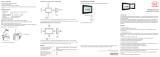
3.3.2 Rear View of the Controller
Receiver (12-pin)
Inputs and outputs (25-pin female)
Light source (5-pin)
Operating voltage (3-pin)
Fig. 9 Connectors at the back of the controller

Seite 10
Functional Principle, Technical Data
optoCONTROL 2500
3.4 Operating Modes
The following operating modes are selectable via a menu-assisted („Select measurement
program“, see Chap. 6.3.6) selection:
Position/Edge
Light source
Receiver
Position of an edge (dark - bright)
A
+26.411 mm
P-P Min Max
+0.812 +25.896 +26.708
EDGELH
Position/Edge
Light source
Receiver
Position of an edge (bright - dark)
A
+14.661 mm
P-P Min Max
+0.972 +14.011 +14.983
EDGEHL
Diameter
Receiver
Light source
Diameter of a target
A
+15.074 mm
P-P Min Max
+0.005 +15.071 +15.076
DIA
GAP
Receiver
Light source
Gap between two targets
A
+11.763 mm
P-P Min Max
+0.487 +11.575 +12.062
GAP
Segment
Receiver
Light source
Distance between two selectable edges (segment)
(in the example segments 2-4)
A
+17.100 mm
P-P Min Max
+16.983 +0.466 +17.450
SEG_2_4
2-Segment
Receiver
Light source
Alternating measurement of two freely selectable seg-
ments (in the example segments 1-4 and 2-3)
A S 1
+14.815 mm
P-P Min Max
+0.012 +14.810 +14.822
2-SEG
A S 2
+11.768 mm
P-P Min Max
+0.010 +11.761 +11.771
2-SEG
Fig. 10 Methods of operating
For each measurement program 2 limits and 2 warnings can be programmed.
For the 2-segment program only 2 limits per segment can be programmed.
Application-specific measurement programs can also be generated by menu.

Seite 11
Functional Principle, Technical Data
optoCONTROL 2500
3.5 Technical Data
Measurement range
0.5 mm ... 34 mm
Measuring rate (sampling rate)
2.3 kHz
Smallest measurable diameter or gap
0.5 mm
Minimum distance from diameter step
(recess) on target to the measuring point
0.2 mm
Distance of light source - receiver
(free space)
150 ... 700 mm
Linearity, typical for calibrated distances
object - receiver:
20 ±5 mm
1
50 ±5 mm
1
100 ±5 mm
2
150 ±5 mm
2
±10 µm
±15 µm
±18 µm
±20 µm
Resolution
3
1 µm
Reproducibility
3 µm
Light source
Semiconductor laser 670 nm, red
Power < 0.39 mW,
Laser Class 1
Analog output voltage 0 to 10 VDC, range ±10 VDC,
selectable
Digital output RS232: max. 115.2 kBaud or
RS422: max. 691.2 kBaud
Switching output Error, 2x limit,
2x warning,
max. 30 VDC; 100 mA;
Error output max. 30 VDC; 100 mA;
separate for each channel
Operating temperature 0 ... 50 °C
Storage temperature -20 up to 70 °C
Cable length
Controller-Laser or Controller - camera
Standard:
Extension:
2 m
3 m or 8 m
Extraneous light Outside of the receiver range appro-
ximately 8.000 Lux (direct radiation
1.000 Lux)
Operating voltage +24 VDC ±15 %, < 1 A
Level of protection IP 64 (Light source, receiver)
IP 40 (controller)
Measurement programs - Edge bright - dark
- Edge dark - bright
- Diameter
- Gap
- Segment
- 2-segment
- 4 user programs (can be edited)
Dimensions
Light source
Receiver
Controller (without connector)
Mounting rail (for light source and receiver)
H x W x D
110 x 72 x 28 (4.33 x 2.83 x 1.10)
54 x 72 x 28 (2.13 x 2.83 x 1.10)
191 x 110 x 45 (7.52 x 4.33 x 1.77)
15 x 30 x 494 (.59 x 1.18 x 19.4)
Weight Controller
Light source
Receiver
Mounting rail
1000 g
400 g
300 g
600 g
Dimensions mm (inches)

Seite 12
Functional Principle, Technical Data
optoCONTROL 2500
Displays - LCD-display (value, maximum,
minimum, (peak-to-peak)
- Measurement indication in mm or
inch, selectable
- Menu language in German or Eng-
lish, selectable
- 3x LED (Power on, Laser on, Error)
Vibration
4
acc. IEC 60068-2-6
2 g / 20 ... 500 Hz
Shock
4
acc. IEC 60068-2-29
15 g / 6 ms
Inputs - Zero point (Zero)
- Synchronization
- Laser on / off (can be turned off via
menu)
Accessories, optional - Cable extensions for light source
and receiver (3 m or 8 m)
- Power supply cable (3 m or 10 m)
- Signal output cable (signal and
switching outputs):
Analog (3 m) + RS232 (3 m)
Analog (3 m) + RS422 (10 m)
The quoted data apply for a constant room temperature of 20 °C, sensor in continuous
operation.
1) Measured at a distance, light source - receiver 150 mm
2) Measured at a distance, light source - receiver 300 mm
3) Display resolution
4) Data apply to the sensor unit
1) +2) Operating Mode: Edge
3.6 Block Diagram
Light source
Laser
Receiver
(Camera)
Sensor signal
processing
(digitaler
signal
processor)
Communi-
cation unit
Display and
operating
unit
User
Input and
outputs
+24 VDCPower supply
ControllerSensor unit
Fig. 11 Block diagram of the ODC2500 measuring system

Seite 13
Functional Principle, Technical Data
optoCONTROL 2500
3.7 Analog Output
Output voltage (without offset): 0 ... 10 VDC
Max. output range (with offset, gain): -10.0 V ... +10.0 VDC
Output span (= 100 % of measurement range): U
OUT
10.0 VDC
Output voltage (with error indication) -10.04 V ... +10.04 VDC
Internal resistance: 100 Ohm
Minimum load resistance: 1 kOhm
Recommended load resistance: 1 MOhm
Maximum capacitive load 47 nF
Analog output, see Chap. 6.4.
3.8 Zero-Setting Input
By briefly connecting (0.5 to 3 s) together the inputs „Set zero“ (Signal and GND) during
measurement, the measurement is set to the default master value, see Chap. 6.3.7.2 .
If a master value has not yet been entered, the measurement is set to 00.000 during zero
setting.
i
Zero-setting input on the 25-pin connector:
Pin 5: Signal Pin 18: GND
If the zero-setting input is activated for between 3 and 6 s (closed), resetting occurs to
the measurement without masters or zeroes.
Pulses which are shorter than 0.5 s or longer than 6 s are not processed.
The zero-setting input is only active in the measurement mode with valid measurements.
In the „2-segment“ operating mode and with erroneous measurements, no zero-setting
is possible.
The zero-setting input only affects the display and the analog output. The digital output is
not affected.
3.9 Synchronization
If two or more optoCONTROL 2500s are operated on the same target, they can be
synchronized to one another, see Chap. 6.5.
As Master, Controller 1 then synchronizes Controller 2.
All synchronization signals are electrically isolated by optocouplers.
3.10 Error Output
If an error is detected by the measurement system (e.g. no target present, too much
extraneous light, etc.), then the switching output „Error“ becomes conducting.
The error output always refers to the unaveraged measurements (at a rate of 2.3 kHz).
The red light emitting diode (Error LED) also indicates the error.
Output wiring, see Chap.
i
The error output is provided on the 25-pin connector.
Pin 1: Error output Pin 2: GND
3.11 Laser Switch-off
In the menu Options you can also activate the switching input for the external laser
switch-off. The light source is then active (Laser on) when the input is short-circuited.
As supplied the input is not activated, so that nothing needs to be connected to the
25-pin socket in order to put the system into operation.

Seite 14
Delivery
optoCONTROL 2500
4. Delivery
4.1 Supplied Items
1 Controller
1 Light source
1 Receiver
1 Mounting rail with mounting screws for light source and receiver
1 25-pin Sub-D plug
1 3-pin circular plug
1 Operating manual
Carefully remove the components of the measuring system from the packaging and
ensure furthermore that the goods are forwarded in such a way that no damage will
occur.
i
Do not touch the optical windows. Dirt on the optical window will eventually affect
the functionality.
Check the measuring system for completeness and transport damage immediately
after unpacking.
Immediately contact your supplier in the case of damage of incompleteness.
4.2 Storage
Storage temperature -20 up to +70 °C
Relative humidity up to 95 % RH, non-condensing
5. Installation and Mounting
5.1 Precautions
No sharp-edged or heavy object should be allowed to affect the cable. The connect-
ing cables from the light source and receiver are compatible with use as trailing cables.
Kinks in the cables must always be avoided.
i
Do not touch the optical windows. Dirt on the optical window will eventually affect
the functionality.
5.2 Mounting the Sensor Unit
The sensor unit, consisting of the light source, receiver and mounting rail, see Fig. 12, is
pre-assembled. The light source can be fitted to the mounting rail at two different dis-
tances (150 or 300 mm) to the receiver.
i
Sensor unit and controller form a unit. Do not change with components of different
serial numbers.
Fig. 12 Mounted sensor unit with controller
The mounting rail must be fixed so that it is not bended respectively twisted.

Seite 15
Installation and Mounting
optoCONTROL 2500
The sensor unit is calibrated in the controller to four different measurement distances:
• Receiver - target: 20 mm and 50 mm,
distance between light source and receiver 150 mm
and
• Receiver - target: 100 mm and 150 mm,
distance between light source and receiver 300 mm.
Other distances of the light source to the receiver are possible, but may slightly affect
the linearity of the measurement. The maximum distance (free space) between the light
source and receiver is 700 mm.
i
Standard setting receiver - target: 20 mm and 50 mm,
distance between light source and receiver: 150 mm
A dimensioned drawing of the sensor unit, see Fig. 13.
With the free mounting of the light source and receiver sensor components, attention
must be given to the precise alignment of the housing edges.
The housing edges must lie in one plane. The maximum angular deviation is 1 °.
A try square or rail are suitable aids for alignment.
The supplied mounting screws or other suitable M4 screws should be used for fixing.
Please note the threaded depth of 5 mm in both components.
For bolting on, the three 4.5 mm through holes in each component can be also used. A
horizontal measurement arrangement reduces contamination on the optical system and
should therefore be preferred.
Mount the sensor only to the existing holes on a flat surface. Clamps of any kind are not
permitted.
> Inaccurate, erroneous measuring values
*
46 (1.84)
Receiver
92
(3.62)
Light source
mm
(inches)
4
(.16)
4 (.16)
63 (2.48)
20 (.79)72 (2.83)15(.59)
28 (1.10)
M4;
5
(.19) tief
M4;
5
(.19) deep
4
(.16)
4
(.16)
22
(.87)
20 (.79)
17 (.67)
54 (2.13)
ø4.5
(.18)
100 (3.94)
ø4.5
(.18)
5 (.19)
46 (1.81)
46
(1.81)
46
(1.81)
20 (.79)
100 (3.94)
40
(1.57)
4
(.16)
63 (2.48)
20 (.79)
30 (1.18)
6 (.24) 120 (4.72)
120 (4.72)
6
(.24)
74 (2.91)ø4.5 (.18)
494 (19.45)
With mounting rail
Calibration distance 300
(11.81)
Light beam
Calibration distance
150
(5.91)
50 (1.97)
5
(.20)
Measuring range
34
(1.34)
14
(.55)
4 (.16)
Fig. 13 Dimensional drawing sensor unit, dimensions in mm (inches), not to scale
Arrows on the mounting rail show you the calibrated target positions
Minimum cable bending radius
Light source (5-pin) flexible: 35 (1.38) fixed: 23 (.91)
Light source extension cable CE2500-x flexible: 35 (1.38) fixed: 23 (.91)
Receiver (12-pin) flexible: 49 (1.93) fixed: 33 (1.39)
Receiver extension cable CE1800-x flexible: 49 (1.93) fixed: 33 (1.39)

Seite 16
Installation and Mounting
optoCONTROL 2500
Connect the light source (5-pin) and the receiver (12-pin) with the controller.
The max. distance between light source and receiver is 700 mm.
i
The light source and receiver must lie in one plane and must not be tilted with re-
spect to another.
Control the centred alignment of the light beam at the receiver after installation of the
light source and of the receiver in the correct displacement. You may control the concen-
tric orientation of the light beam both in the horizontal and the vertical orientation.
For this purpose it is recommended, to keep a white paper as a projection plane ahead
of the receiver and to cover the window halfway through, see Fig. 14, see Fig. 15. For
the vertical orientation also the color filter on the sensors surface can be used. The light
beam should illuminate this up to the edge (±0.5 mm) symmetrically. For the horizontal
alignment use the engraved lines on the sensors surface, which have to be lluminated
also.
You may loosen the light source for an accurate positioning if required.
Fig. 14 Vertical adjustment controlling
with white paper
Fig. 15 Horizontal adjustment controlling
with white paper

Seite 17
Installation and Mounting
optoCONTROL 2500
5.3 Mounting the Controller
The controller can be mounted in any orientation.
The controller should be mounted with four M4 screws (not included in the supplied
items) on a flat mounting plate.
Make sure there is sufficient space for the connector and cable.
mm
(inches)
receiver
24 VDC
in / out
laser
3 sec - main menu:
- select options...
- select program...
- edit program...
3 sec - zero
1 sec - reset min / max /
peak to peak
1 sec - full display / zoom reading
ESC
ESC
optoCONTROL
receiver
24 VDC
in / out
laser
45 (1.77)
54 (2.12)
SCA2500 / SCD2500
Receiver
cable
26.5 (1.04)
30.3 (1.19)
25 (.98)
41 (1.61)
86.5 (3.40)
47 (1.85)
92.5 (3.64)
97 (3.82)
110 (4.33)
155 (6.10)
191.1 (7.52)
195.2
(7.68)
ø4.6
(.18)
PC2500-3
receiver
24 VDC
in / out
laser
optoCONTROL
receiver
24 VDC
in / out
laser
13 (.52)
13 (.52)
power on
errorlaser on
41 (1.61)
137 (5.40)
ø7.5
(.30)
Fig. 16 Dimensional drawing controller, dimensions in mm (inches), not to scale
Minimum cable bending radius
Signal output cable
SCA2500 / SCD2500
flexible: 96 mm (3.78 inches) fixed: 40 mm (1.57 inches)
Supply cable PC2500-3 flexible: 70 mm (2.75 inches) fixed: 50 mm (1.97 inches)
5.4 Supply Voltage
Connect the 24 VDC female connector with a 24 V power supply.
The operating voltage is preferably connected via a screened two-core cable, e.g. via the
supply cable PC2500-3. Route the cable screen to a potential equalization terminal in the
vicinity of the power supply unit. The controller contains a inverse-polarity protection.
1 3
2
Pin-no. Signal Conductor coloring
PC2500, (old version)
1
2
3
Housing
GND of operating voltage
N.C.
+24 VDC (±15 %), < 1 A
Cable screen
black
---
red
tin-plated
(brown or blue)
(white)
Fig. 17 3-pin male cable connector (type Binder), view on solder pin side
i
The operating voltage is protected against reverse connection.
The sensor should be furnished with the expected noise on the supply voltage
caused by inductive loads (eg motors, contactors, solenoid valves, etc.) from a
small separate power supply for measuring equipment.

Seite 18
Installation and Mounting
optoCONTROL 2500
Controller ODC 2500
PS2020
230 VAC
PE
N L
PS2020
Fig. 18 Power supply of the ODC2500 with a PS2020
5.5 Connecting of Terminal Equipment
5.5.1 Connectivity Overview
SCD2500-x/IF2008
SCD2500-x/10/RS422
SCD2500-x/3/RS232
SCA2500-x
SCD2500-x/CSP
IF2008
Controller ODC 2500
CSP2008
V
RS232
RS422
Fig. 19 Connectivity ODC2500
Pin-No. Signal Signal type / connector type
1 Error output (Signal) Switching output
14 Error output (GND) Switching output
2 High limit (Signal) Switching output
15 High/low limit (GND) Switching output (common connection)
3 Low limit (Signal) Switching output
16 High warning (Signal) Switching output
4 High/low warning (GND) Switching output (common connection)
17 Low warning (Signal) Switching output
5 Zero point (Signal) Switching input (Zero)
18 Zero point (GND) Reference potential for ZERO
6 Input Laser OFF (Signal) Switching input
19 Input Laser OFF (GND) Reference potential for switching input
20 RS422 Receive (inverted) Optocoupler input (positive)
7 RS422 Receive (positive) Optocoupler input (negative)
8 RS422 Send (positive) Serial output (negative impedance)
21 RS422 Send (inverted) Serial output (positive impedance)
9 RS232 Receive (RxD) Serial input (RS232)
22 RS232 DGND Reference potential for RS232
10 RS232 Send (TxD) Serial Output (RS232)
23 Synchronization output (+) Digital output (SYNC)
11 Synchronization output (-) Reference potential (DGND)
24 Synchronization input (+) Optocoupler - Input (positive)
12 Synchronization input (-) Optocoupler - Input (negative)
25 Analog output (AGND) Reference potential for analog signal
13 Analog output (Signal) Analog signal (voltage)
Fig. 20 Sub-D connector, 25-pin

Seite 19
Installation and Mounting
optoCONTROL 2500
Comment:
• All GDN signals are connected internally with one another and with the minus pole
(GND) of the 24 V operating voltage.
• DGND and AGND are internally electrically connected, but isolated from the minus
pole (GND) of the 24 V operating voltage.
13 1
1425
Fig. 21 25-pin Sub-D male connector, solder pin side
5.5.2 PCI-Interface Card IF2008
The IF2008 enables the synchronous capture of up to 4 digital sensor signals and
2 encoders.
An ODC 2500 Controller is connected to the IF2008 Interface card from MICRO-EPSILON
Eltrotec GmbH via the SCD2500-x/IF2008 signal output cable on the socket X1 (Sensor
1).
A second ODC 2500 can be plugged onto the X2 socket (Sensor 3).
For the connection of more than two ODC 2500 sensors to one IF2008 you require an
IF2008-Y adapter cable from MICRO-EPSILON Eltrotec GmbH.
The interface parameters on the ODC 2500 must be set to the active RS422 interface and
the following standard settings made:
Baud rate: 691200 Baud
Data format: 8 data bits, no parity, 1 stop bit (8, N, 1)
First switch on downstream computers and after that the controller.
All inputs are electrically isolated by optocouplers both on the ODC 2500 controller and
on the IF2008 Interface Card.
Further information can be found in the documentation for the IF2008, ICONNECT and
LibOPTO from MICRO-EPSILON Eltrotec GmbH.
Controller ODC 2500
IF2008
PC
Signal output cable
SCD2500-x/IF2008
Fig. 22 System setup for the operation of Interface card IF2008

Seite 20
Installation and Mounting
optoCONTROL 2500
Pin on Controller
(HD-Sub 25)
Inferface card IF2008
Bush X1 (oder X2)
15-pin Sub-D,
IF2008
IF2008,
X1 und X2,
15-pin Sub-D
Controller
ODC 1
7 Sensor 1 (3) TxD+ 2
20 Sensor 1 (3) TxD- 1
8 Sensor 1 (3) RxD+ 4
21 Sensor 1 (3) Rxd- 3
24 Sync In+ 6
12 GND 15
NC 7
NC 8
NC 9
NC 10
Controller
ODC 2
7 Sensor 2 (4) TxD+ 2
20 Sensor 2 (4) TxD- 1
8 Sensor 2 (4) RxD+ 4
21 Sensor 2 (4) RxD- 3
24 Sync In+ 6
12 GND 15
Fig. 23 Pin assignment on the RS422 between IF2008 and ODC2500
5 1
10 6
15 11
Fig. 24 15-pin HD sub-minature connector, viewed on solder side.
25-pin
Sub-D
Signal
15-pin
Sub-D
Core colors
1 Error output (Signal) red
14 Error output (GND) blue
2 High limit (Signal) violet
15 High/low limit (GND) black and brown
3 Low limit (Signal) white
16 High warning (Signal) pink
4 High/low warning gray and gray / pink
17 Low warning (Signal) red / blue
20 RS422 Receive (inverted) 1
7 RS422 Receive (positive) 2
8 RS422 Send (positive) 4
21 RS422 Send (inverted) 3
24 Synchronization input (+) 6
12 Synchronization input (-) 15
25 Analog output (AGND) black (inside conductor)
13 Analog output (Signal) green
black (outer shield to connector housing 25-pin.)
Fig. 25 Pin assignment for SCD2500-x/IF2008 (15-pin)
/