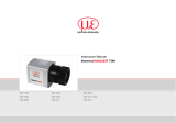
Instruction Manual
thermoMETER CSVideo
CSVM-2L
CSVM-2H

MICRO-EPSILON
MESSTECHNIK
GmbH & Co. KG
Königbacher Strasse 15
94496 Ortenburg / Germany
Tel. +49 (0) 8542 / 168-0
Fax +49 (0) 8542 / 168-90
www.micro-epsilon.com
Certified acc. to DIN EN ISO 9001: 2008
Infrared sensor

thermoMETER CSVideo
Contents
1. Safety ........................................................................................................................................ 7
1.1 Symbols Used ................................................................................................................................................. 7
1.2 Warnings .......................................................................................................................................................... 7
1.3 Notes on CE Identification ............................................................................................................................... 9
1.4 Proper Use ..................................................................................................................................................... 10
1.5 Proper Environment ....................................................................................................................................... 10
2. Technical Data ........................................................................................................................ 11
2.1 Functional Principle ....................................................................................................................................... 11
2.2 Sensor Models ............................................................................................................................................... 12
2.3 General Specification .................................................................................................................................... 12
2.4 Electrical Specification .................................................................................................................................. 13
2.5 Measurement Specification ........................................................................................................................... 14
3. Delivery ................................................................................................................................... 15
3.1 Unpacking ...................................................................................................................................................... 15
3.2 Storage .......................................................................................................................................................... 15
4. Optics ...................................................................................................................................... 16
5. Mechanical Installation .......................................................................................................... 17
6. Electrical Installation .............................................................................................................. 18
6.1 Cable Connections ........................................................................................................................................ 18
6.2 Power Supply ................................................................................................................................................. 18
6.3 Pin Assignment .............................................................................................................................................. 19
6.3.1 7-pin Connector (Current Loop/ Alarm/ Laser) ............................................................................ 19
6.3.2 4-pin Connector (USB) ................................................................................................................. 19
6.4 Analog Mode ................................................................................................................................................. 20
6.5 Digital Mode ................................................................................................................................................... 21
6.6 Maximal Loop Impedance ............................................................................................................................. 22
6.7 Options .......................................................................................................................................................... 23
6.8 Focusing and Video Sighting ........................................................................................................................ 24

thermoMETER CSVideo
7. Instructions for Operation...................................................................................................... 25
7.1 Cleaning ......................................................................................................................................................... 25
8. Software .................................................................................................................................. 26
8.1 Installation ...................................................................................................................................................... 26
8.2 System Requirements ................................................................................................................................... 26
8.3 Main Features ................................................................................................................................................ 26
9. Communication Settings ........................................................................................................ 27
9.1 Serial Interface ............................................................................................................................................... 27
9.2 Protocol .......................................................................................................................................................... 27
9.3 Digital Command Set .................................................................................................................................... 28
10. Basics of Infrared Thermometry ............................................................................................ 30
11. Emissivity ................................................................................................................................ 31
11.1 Definition ........................................................................................................................................................ 31
11.2 Determination of Unknown Emissivity ........................................................................................................... 31
11.3 Characteristic Emissivities ............................................................................................................................. 32
12. Warranty ................................................................................................................................. 33
13. Service, Repair ....................................................................................................................... 34
14. Decommissioning, Disposal .................................................................................................. 34

thermoMETER CSVideo
Appendix
A 1 Accessories ............................................................................................................................ 35
A 1.1 Mounting Bracket .......................................................................................................................................... 35
A 1.2 Air Purge Collar .............................................................................................................................................. 36
A 1.3 Water Cooled Housing .................................................................................................................................. 37
A 1.4 High Temperature Cable ................................................................................................................................ 37
A 2 Factory Default Settings ......................................................................................................... 38
A 3 Emissivity Table Metals .......................................................................................................... 39
A 4 Emissivity Table Non Metals .................................................................................................. 42
A 5 Smart Averaging ..................................................................................................................... 44

thermoMETER CSVideo

Page 7
Safety
thermoMETER CSVideo
1. Safety
The handling of the system assumes knowledge of the instruction manual.
1.1 Symbols Used
The following symbols are used in the instruction manual:
Indicates a hazardous situation which, if not avoided, may result in minor or
moderate injuries.
Indicates a situation which, if not avoided, may lead to property damage.
Indicates a user action.
i
Indicates a user tip.
Measure
Indicates a hardware or a button/menu in the software.
1.2 Warnings
Connect the power supply and the display/output device in accordance with the safety regulations for electri-
cal equipment.
> Danger of injury
> Damage to or destruction of the infrared sensor
Avoid shock and vibration to the infrared sensor.
> Damage to or destruction of the infrared sensor
The power supply must not exceed the specified limits.
> Damage to or destruction of the infrared sensor
Protect the USB cable against damage.
> Damage to the infrared sensor, failure of the measuring device

Page 8
Safety
thermoMETER CSVideo
No solvent-based cleaning agents may have an effect on the sensor (neither for the optics nor the housing).
> Damage to or destruction of the infrared sensor
Avoid static electricity, arc welders and induction heaters. Keep away from very strong EMF (electromagnetic
fields).
> Damage to or destruction of the infrared sensor
Avoid abrupt changes in operating temperature.
> Faulty measurement
Avoid that the measurement object fills the field of optics completely.
> Faulty measurement
Never connect a supply voltage.
> Destruction of the output
Make sure to keep the optical path clear of any obstacles.
> Faulty measurement

Page 9
Safety
thermoMETER CSVideo
1.3 Notes on CE Identification
The following applies to the thermoMETER CSVideo:
- EU directive 2004/108/EC
- EU directive 2011/65/EC, “RoHS“ category 9
Products which carry the CE mark satisfy the requirements of the quoted EU directives and the European
standards (EN) listed therein. The EC declaration of conformity is kept available according to EC regulation,
article 10 by the authorities responsible at
MICRO-EPSILON MESSTECHNIK
GmbH & Co. KG
Königbacher Straße 15
94496 Ortenburg / Germany
The system is designed for use in industry and laboratory and satisfies the requirements of the standards
- EN 61326-1: 2006
- EN 61326-2-3: 2006
- EN 61010-1: 2001
The system satisfies the requirements if they comply with the regulations described in the instruction manual
for installation and operation.

Page 10
Safety
thermoMETER CSVideo
1.4 Proper Use
- The thermoMETER CSVideo is designed for use in industrial and laboratory areas. It is used for non-con-
tact temperature measurement.
- The system may only be operated within the limits specified in the technical data, see Chap. 2..
- Use the system in such a way that in case of malfunctions or failure personnel or machinery are not endan-
gered.
- Take additional precautions for safety and damage prevention for safety-related applications.
1.5 Proper Environment
- Protection class: IP 65
- Operating temperature:
Sensor: -20 ... 70 °C (-4 ... +158 °F)
1
Controller: 0 ... 85 °C (+32 ... +185 °F)
Cable sensor - controller: max. 80 °C (+176 °F)
2
- Storage temperature: -40 ... 85 °C (-40 ... +185 °F)
- Humidity: 10 - 95 %, non-condensing
- EMC acc. to: EN 61326-1: 2006
EN 61326-2-3: 2006
EN 61010-1: 2001
Avoid abrupt changes in operating temperature.
> Faulty measurement
1) Laser will turn off automatically at operating temperatures > 50 °C.
2) Optional: High temperature cable: 180 °C (+356 °F), see Chap. A 1.4

Page 11
Technical Data
thermoMETER CSVideo
2. Technical Data
2.1 Functional Principle
The sensors of the thermoMETER CSVideo are noncontact infrared temperature sensors.
They calculate the surface temperature based on the emitted infrared energy of objects, see Chap. 10.. The
alignment of the sensor can be done with the integrated video sighting and crosshair laser aiming.
The sensor housing of the thermoMETER CSVideo sensor is made of stainless steel (IP 65/ NEMA-4 rating) –
the controller is placed in a separate box made of die casting zinc.
i
The thermoMETER CSVideo sensor is a sensitive optical system. Please use only the thread for me-
chanical installation.
Avoid mechanical violence on the sensor.
> Destruction of the system

Page 12
Technical Data
thermoMETER CSVideo
2.2 Sensor Models
Model Measuring range Spectral response Typical applications
CSVM-2L 250 up to 800 °C
1.6 μm Metals and ceramic surfaces
CSVM-2H
385 up to 1600 °C
2.3 General Specification
Sensor
Protection class IP 65
Operating temperature
1
-20 ... 70 °C
Storage temperature -40 ... 85 °C
Relative humidity 10 ... 95 %, non condensing
Material Stainless steel
Dimensions 118.5 mm x 50 mm, M48x1.5
Weight 600 g
Cable length analog and alarm 3 m, 5 m, 10 m
USB 5 m (inclusive), 10 m, 20 m
Cable diameter 5 mm
Operating temperature cable max. 80 °C
2
Vibration IEC 68-2-6: 3 G, 11 – 200 Hz, any axis
Shock IEC 68-2-27: 50 G, 11 ms, any axis
Software inclusive
1) Laser swill turn off automatically at operating temperatures > 50 °C ab.
2) Optional: high temperature cable: 180 °C, see Chap. A 1.4

Page 13
Technical Data
thermoMETER CSVideo
2.4 Electrical Specification
Power supply 5 - 28 VDC
Current draw (laser) 45 mA @ 5 V
20 mA @ 12 V
12 mA @ 24 V
Aiming laser Crosshair laser, 635 nm, 1 mW, On/Off via external switch
(needs to be installed by user before start-up) or software
Video sighting Digital (USB 2.0), 640 x 480 px, FOV 3.1 ° x 2.4 °
Output/ analog 4 – 20 mA current loop
Alarm output Programmable open collector output at RxD pin
(0 - 30 V/ 500 mA)
Output impedances max. loop resistance 1000 Ω
(in dependence on supply voltage)
Output digital USB 2.0

Page 14
Technical Data
thermoMETER CSVideo
2.5 Measurement Specification
Model CSVM-2L CSVM-2H
Temperature range (scalable) 250 ... 800 °C 385 ... 1600 °C
Spectral range 1.6 μm 1.6 μm
Optical resolution 150:1 300:1
System accuracy
1
±(0.3 % of reading +2 °C)
2
Repeatability
1
±(0.1 % of reading +1 °C)
2
Temperature resolution 0.1 °C
Exposure time (90 % signal) 10 ms
Emissivity / Gain 0,100 … 1,100 (adjustable via switches on sensor or via software)
IR window correction 0,100 … 1,100 (adjustable via software)
Signal processing Average, peak hold, valley hold, extended hold functions with threshold
and hysteresis (adjustable via software)
1) At operating temperature 23 ± 5 °C
3) e= 1/ Response time 1 s

Page 15
Delivery
thermoMETER CSVideo
3. Delivery
3.1 Unpacking
1 thermoMETER CSVideo infrared sensor
1 Mounting nut and mounting bracket (fixed)
1 USB interface cable
1 CompactConnect Software-CD
1 Instruction manual
Check the delivery for completeness and shipping damage immediately after unpacking.
In case of damage or missing parts, please contact the manufacturer or supplier immediately.
You will find optional accessories in appendix, see Chap. A 1.
3.2 Storage
- Storage temperature: -40 ... 85 °C (-40 ... +185 °F)
- Humidity: 10 ... 95 %, non-condensing

Page 16
Optics
thermoMETER CSVideo
4. Optics
The vario optics of the thermoMETER CSVideo allows a smooth focusing of the optics to the desired dis-
tance. The sensors are available in two optic versions:
Optics Focus adjustable in the range
SF 200 mm until infinity
CF 90 mm until 250 mm
The size of the measuring object and the optical resolution of the infrared thermometer determine the maxi-
mum distance between sensor and measuring object.
Avoid that the measurement object fills the field of optics completely.
> Measurement error
Consequently, the spot should at all times have at least the same size like the object or should be smaller
than that. The following tables show the diameter of the measuring spot for some selected distances. The
spot size refers to 90 % of the radiation energy.
The distance is always measured from the front edge of the sensor.
2L: SF optics (D:S = 150:1)
Spot size mm 1.3 2.0 3 4.7 7.3 10.7 16.7 33.3
Measurement distance mm 200 300 450 700 1100 1600 2500 5000
2L: CF optics (D:S = 150:1)
Spot size mm 0.6 0.8 1.0 1.2 1.4 1.7
Measurement distance mm 90 120 150 180 210 250
2H: SF optics (D:S = 300:1)
Spot size mm 0.7 1.0 1.5 2.3 3.7 5.3 8.3 16.7
Measurement distance mm 200 300 450 700 1100 1600 2500 5000
2H: CF optics (D:S = 300:1)
Spot size mm 0.3 0.4 0.5 0.6 0.7 0.8
Measurement distance mm 90 120 150 180 210 250

Page 17
Mechanical Installation
thermoMETER CSVideo
5. Mechanical Installation
The thermoMETER CSVideo is equipped with a metric M48x1.5 thread and can be installed either directly via
the sensor thread or with help of the supplied mounting nut (standard) and fixed mounting bracket (standard)
to a mounting device available.
Avoid mechanical violence on the sensor.
> Destruction of the system
Fig. 1 Dimensional drawing thermoMETER CSVideo sensor
Dimensions in mm, not to scale
Make sure to keep the optical path clear of any objects.
> Faulty measurement

Page 18
Electrical Installation
thermoMETER CSVideo
6. Electrical Installation
6.1 Cable Connections
The thermoMETER CSVideo has two connector plugs integrated in the sensor backplane, see Fig. 2.
Fig. 2 Connectors
Therefore an opening of the sensor for cable assembling is not necessary.
For connection to a PC you can use the supplied 5 m USB cable with a 4-pin sensor connector (lengths of
10 m and 20 m are optional available.
For the analog connection (4 - 20 mA current loop, alarm, laser) a cable with a 7-pin plug is needed. This
cable is not included in the scope of supply and has to be ordered separately.
Lengths of 3, 8 and 15 m are available. Please use the original ready-made, fitting connection cables.
6.2 Power Supply
Please use a separate, stabilized power supply unit with an output voltage of 5 - 28 VDC which can supply
100 mA. The ripple should be max. 200 mV.
Please use shielded cables only for all power and data lines.
The sensor shield has to be grounded.

Page 19
Electrical Installation
thermoMETER CSVideo
6.3 Pin Assignment
6.3.1 7-pin Connector (Current Loop/ Alarm/ Laser)
Pin Designation Color (orginal sensor cable)
1 - yellow
2 LOOP - brown
3 LOOP + white
4 Alarm green
5 LASER - gray
6 LASER + pink
7 -
Fig. 3 7-pin round connector, view from outside
6.3.2 4-pin Connector (USB)
Pin Designation Color (original sensor cable)
1 VCC yellow
2 GND brown
3 D- white
4 D+ green
Fig. 4 4-pin round connector, view from outside

Page 20
Electrical Installation
thermoMETER CSVideo
6.4 Analog Mode
If the thermoMETER CSVideo is used as analog device the sensor provides beside the 4 - 20 mA signal in
addition an alarm output (open-collector). To activate the alarm output and set the alarm threshold value the
software is needed.
The supply line for the sighting laser must be led via a switch or pushbutton, which has to be installed
max. 2 m away from installation site of the sensor.
The sensor configuration and adjustment can be done on site with a laptop or tablet PC. The USB cable can
be connected to the sensor during operation of the sensor (hot plug & play).
Page is loading ...
Page is loading ...
Page is loading ...
Page is loading ...
Page is loading ...
Page is loading ...
Page is loading ...
Page is loading ...
Page is loading ...
Page is loading ...
Page is loading ...
Page is loading ...
Page is loading ...
Page is loading ...
Page is loading ...
Page is loading ...
Page is loading ...
Page is loading ...
Page is loading ...
Page is loading ...
Page is loading ...
Page is loading ...
Page is loading ...
Page is loading ...
Page is loading ...
Page is loading ...
/