Page is loading ...

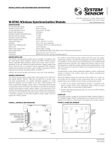
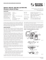
FIGURE 1. CONTROLS AND INDICATORS:
C1095C-00
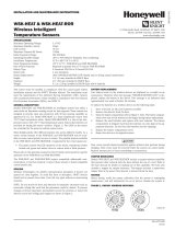
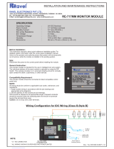
FIGURE 2. FACEPLATE INTERIOR:
MAGNET LOCA
TION
(DO NOT REMOVE)
C1098-00
SPECIFICATIONS
Maximum Operating Voltage: 3.3 VDC
Maximum Current Draw: 5.0 mA (LED on)
Average Operating Current: 210 µA, 3.9k EOL
EOL Resistance: 3.9K Ohms
Maximum IDC Wiring Resistance: 10 Ohms
Maximum IDC Voltage: 3.2 Volts
Maximum Average IDC Current: 5.5 µA
Maximum Transmit RF Power: 17 dBm
Radio Frequency Range: 902-928 MHz
Temperature Range: 32°F to 120°F (0°C to 49°C)
Humidity: 10% to 93% Non-condensing
Battery Type: 4 Panasonic CR123A or 4 Duracell DL123A
Battery Life: 2 year minimum
Battery Replacement: Upon TROUBLE BATTERY LOW display and/or during annual maintenance
Dimensions: 4¼ in. H x 4¼ in. W x 1½ in. D
Accessories: SMB500 Electrical Box (preferred mounting option)
BEFORE INSTALLING
This information is included as a quick reference installation guide. Refer to
the control panel installation manual and the SWIFT Wireless Manual for de-
tailed system information. If the modules will be installed in an existing op-
erational system, inform the operator and local authority that the system will
be temporarily out of service. Disconnect power to the control panel before
installing the modules.
NOTICE: This manual should be left with the owner/user of this equipment.
GENERAL DESCRIPTION
The WSK-MONITOR Monitor Module is intended for use with a wireless gate-
way or wireless fire alarm control panel (FACP) to interface with a device
having contacts used to signal status conditions. The input to the monitor
module is non-latching and does not require a reset. The device communi-
cates through a robust, bi-directional mesh network to the gateway and/or
FACP. Rotary dial switches are provided for setting the module’s address. The
module has a panel controlled LED indicator. (Figure 1)
FACEPLATE
The faceplate includes a magnet for activation and tamper resistance (Figure
2). The faceplate magnet activates communication to the panel, therefore, the
faceplate must be installed for the module to work properly. The magnet also
activates a supervisory tamper fault at the panel if the nameplate is removed.
Do NOT remove this magnet. The faceplate for a wireless module CANNOT be
replaced with the faceplate of a standard wired module.
BATTERY REPLACEMENT
Low battery levels on the wireless devices are displayed as a trouble in an
annunciator. Therefore when the message “TROUBLE BATTERY LOW” is dis-
played, replace the battery in the device. This message is an indication that
approximately one week of battery life remains.
COMPATIBILITY REQUIREMENTS
To ensure proper operation, this module shall be connected to a compatible
Silent Knight system control panel (list available from Silent Knight).
To replace the batteries in a wireless device use the following steps:
1. Have 4 CR123A (or DL123A) batteries available
2. Remove the faceplate from the module.
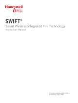
3. Open the battery compartment refer to Figure 3.
4. Remove the used batteries and replace with new batteries. The battery com-
partment is designed such that the batteries can only align in the appropri-
ate direction. Do not force the batteries into the openings.
5. Replace the battery compartment cover.
6. Replace the faceplace.
I56-4271-000
INSTALLATION AND MAINTENANCE INSTRUCTIONS
12 Clintonville Road, Northford, CT 06472-1610
Phone: 203-484-7161 Fax: 203-484-7118
www.silentknight.com
WSK-MONITOR
Wireless Monitor Module
1 I56-4271-000
03-02

SPACING
Wireless technologies can exhibit communication disruption if devices are
spaced too close together. To avoid this form of disruption, SWIFT devices
should not be placed closer than 2 feet (60 cm) apart without an intervening
structure.
MOUNTING
The WSK-MONITOR mounts directly to an SMB500 electrical box (see Figure
4). To avoid interference with the wireless network metal electrical boxes are
NOT recommended. Non-metal surface mounted electrical boxes (SMB500)
are available from Silent Knight. If not using an SMB500, the minimum
mounting opening dimensions for the WSK-MONITOR are 4 in. X 3¾ in. x
1½ in. deep.
NOTE: Do not attach the module to temporary structures such that the place-
C1096-00
C1097-00
FIGURE 4. MODULE MOUNTING:FIGURE 3. BATTERY COMPARTMENT:
BATTERY
COMPARTMENT
DOOR
BATTERY
COMPARTMENT
C2002-00
This device complies with part 15 of the FCC Rules. Operation is subject to the following two conditions:
1. This device may not cause harmful interference, and
2. This device must accept any interference received, including interference that may cause undesired operation.
WARNING: Do not make changes to the equipment. Changes or modifications not expressly approved by the manufacturer could void the user’s authority to operate the equipment.
FCC STATEMENT
Use of these products in combination with non-Honeywell products in a wireless mesh
network, or to access, monitor or control devices in a wireless mesh nework via the inter-
net or another external wide area network, may require a separate license from Sipco, LLC.
For more information, contact Sipco, LLC or Ipco, LLC at 8215 Roswell Rd., Building 900,
Suite 950, Atlanta, GA 303350, or at www.sipocollc.com or www.intusiq.com.
LICENSING STATEMENT
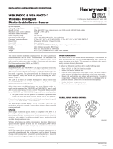
FIGURE 5. TYPICAL MONITORING CONFIGURATION:
WIRELESS
MONITOR MODULE
ONLY ONE UL LISTED CONTACT
CLOSURE MAY BE USED
POWER LIMITED
3.1 VDC MAX
3.9K EOL
RESISTOR
A2143-10
INSTALL CONTACT CLOSURE DEVICES PER
MANUFACTURER’S INSTALLATION INSTRUCTIONS.
W-MMF MUST BE WITHIN 3 FEET OF MONITORED DEVICE WHEN
USING FIELD WIRING OR 20 FEET IN NON-METALLIC CONDUIT.
C1099B-02
ment could be altered.
WIRING
NOTE: All wiring must conform to
applicable local codes, ordinances,
and regulations. This module is in-
tended for power limited wiring only.
WIDP-MONITOR must be within 3
feet of monitored device when using
field wiring or 20 feet in non-metallic
conduit.
1. Install module wiring in accor-
dance with the job drawings
and appropriate wiring dia-
grams.
2. Set the address on the module
per job drawings.
3. Secure module to electrical
box (supplied by installer), as
shown in Figure 4.
2 I56-4271-000
©2017 Honeywell. 03-02
Silent Knight
®
and Honeywell
®
are registered trademarks of Honeywell International, Inc.
/