Page is loading ...

The wireless synchronization module operates from 24V power with supple-
mental battery support. A trouble will be generated at the panel if batteries are
not installed or at a low battery level. Synchronization is not available during
supplemental battery operation. The supplemental batteries enable the wire-
less transceiver to continue to support wireless mesh communications so that
other devices that are its parents or children are not affected by the loss of the
24V connection.
Synchronization of only wireless notification appliances within a single mesh
network is inherent in the wireless system and a wireless synchronization
module is not needed.
Panels offer different feature sets across the various models. As a result, cer-
tain features may be available on some control panels, but not on others. The
possible feature sets available with the wireless synchronization include:
• An LED on the wireless synchronization module is controlled by the
panel to indicate device status. Operational modes include red, green
and amber colors in various solid or blink patterns.
• W-SYNC addressing requirements will vary; refer to the SWIFT Wireless
Gateway Manual.
FACEPLATE
The faceplate includes a magnet for activation and tamper resistance (Figure 2).
The faceplate magnet activates communication to the panel and must be in-
stalled for the module to work properly. The magnet also activates a supervi-
SPECIFICATIONS
Normal Operating Voltage: 18 to 30 VDC
Maximum Current Draw: 60 mA (in alarm)
Average Operating Current: 910 µA (with 3.9k ELR)
Monitor EOL Resistance: 3.9K Ohms
Maximum Monitor Wiring Resistance: 10 Ohms
Maximum Monitor Voltage: 3.2 Volts
Maximum Transmit RF Power: 17 dBm
Radio Frequency Range: 902-928 MHz
Temperature Range: 32°F to 120°F (0°C to 49°C)
Humidity: 10% to 93% Non-condensing
Battery Type (Supplemental): 4 Panasonic CR123A or 4 Duracell DL123A
Battery Life: 2 year minimum
Battery-only Current Draw: 268 µA (with 3.9k ELR)
Battery Replacement: Upon TROUBLE BATTERY LOW display and/or during annual maintenance
Dimensions: 4¼ in. H x 4¼ in. W x 1½ in. D
Accessories: SMB500 Electrical Box (preferred mounting option)
BEFORE INSTALLING
This wireless synchronization module must be installed in compliance with
the control panel system installation manual, the SWIFT Wireless Gateway
Manual, applicable NFPA standards, national and local Fire codes and the re-
quirements of the AHJ (Authority Having Jurisdiction). Regular testing of the
devices should be done in accordance with the appropriate NFPA standards.
Modules offer maximum performance when installed in compliance with the
National Fire Protection Association (NFPA); see NFPA 72.
NOTICE: This manual should be left with the owner/user of this equipment.
GENERAL DESCRIPTION
The wireless synchronization module works with System Sensor wireless AV
base models WAV-RL, WAV-WL, WAV-CRL and WAV-CWL to provide audio
and visual synchronization of a wireless notification appliance to a wired
notification appliance and is intended for use with a wireless gateway. The
device communicates through a robust, Class A bi-directional mesh network
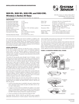
to the gateway and/or FACP. Rotary dial switches are provided for setting the
wireless synchronization module’s address (Figure 1). Synchronization is only
available with notification appliances that use the System Sensor synchroniza-
tion protocol. The W-SYNC also provides wireless control and monitoring of
a Notification Appliance Circuit (NAC) expander or power supply. It does not
support the "whoop" pattern.
I56-6518-001
INSTALLATION AND MAINTENANCE INSTRUCTIONS
W-SYNC Wireless Synchronization Module
3825 Ohio Avenue, St. Charles, Illinois 60174
1-800-SENSOR2, FAX: 630-377-6495
www.systemsensor.com
FIGURE 1. CONTROLS AND INDICATORS
Unsupervised Control Output +
Unsupervised Control Output –
Trouble Monitor Input +
Trouble Monitor Input –
24 VDC Input +
24 VDC Common –
Unsupervised Sync Output +
Unsupervised Sync Output –
Rotary Dial
Addressing
Switches
C1095-04
FIGURE 2. FACEPLATE INTERIOR
Faceplate
Magnet
(DO NOT
REMOVE)
C1098-03
1 I56-6518-001
09/10/2018

sory tamper fault at the panel if the nameplate is removed. Do NOT remove
this magnet. The faceplate for a wireless module CANNOT be replaced with
the faceplate of a standard wired module.
COMPATIBILITY REQUIREMENTS
To ensure proper operation, this module shall be connected to a compatible
system control panel.
BATTERY REPLACEMENT
Low battery levels on the wireless devices are displayed as a trouble in the
FACP or annunciator. Therefore when the message “TROUBLE BATTERY
LOW” is displayed, replace the battery in the device. This message is an indi-
cation that approximately one week of battery life remains.
To replace the batteries in a wireless device use the following steps:
1. Have 4 CR123A (or DL123A) batteries available.
2. Remove the faceplate from the module.
3. Open the battery compartment. (See Figure 3.)
4. Remove the used batteries and replace with new batteries. The battery
compartment is designed such that the batteries can only align in the ap-
propriate direction. Do not force the batteries into the openings.
5. Replace the battery compartment cover.
6. Replace the faceplace.
FIGURE 3. BATTERY COMPARTMENT (SHOWN WITH DOOR OPEN)
C2002-03
FIGURE 4. MODULE MOUNTING:
C1096-00
C1097-00
SPACING
Wireless technologies can exhibit communication disruption if devices are
spaced too close together. To avoid this form of disruption, SWIFT devices
should not be placed closer than 2 feet (60 cm) apart without an intervening
structure.
MOUNTING
The W-SYNC mounts directly to an SMB500 electrical box. (See Figure 4.) To
avoid interference with the wireless network metal electrical boxes are NOT
recommended. Non-metal surface mounted electrical boxes (SMB500) are
available from Honeywell. If not using an SMB500, the minimum mounting
opening dimensions for the W-SYNC are 4 in. X 3¾ in. x 1½ in. deep.
NOTE: Do not attach the module to temporary structures such that the place-
ment could be altered.
WIRING
NOTE: All wiring must conform to applicable local codes, ordinances, and
regulations. This module is intended for power limited wiring only. W-SYNC
must be within 3 feet of the connected device when using field wiring or
20 feet in the same room in non-metallic conduit.
1. Install module wiring in accordance with the job drawings and appropri-
ate wiring diagrams.
2. Set the address on the module per job drawings.
3. Secure module to electrical box (supplied by installer), as shown in
Figure 4.
Several W-SYNC applications provide synchronization between wireless AV
devices and wired AV devices. For applications using W-SYNC with MDL3, see
Figure 5. For all other compatible applications, see the W-SYNC section of the
SWIFT® Instruction Manual.
2 I56-6518-001
09/10/2018

FIGURE 5. MDL3/W-SYNC WIRING: SYNCHRONIZING WIRED AND WIRELESS NAC CIRCUITS
FACP
+
–
+
–
+
–
+
–
+
–
+
–
}
}
}
}
HORN
CONTROL
ZONE 1
IN
ZONE 2
IN
SLAVE
IN
+
–
+
–
+
–
+
–
}
}
}
}
ZONE 1
OUT
ZONE 2
OUT
NAC
SLAVE IN
SLAVE
OUT
TEMP JUMP OFF
NAC 1
NAC 2
}
B+
B–
}
B+
B–
To next L-Series
(or SpectrAlert Advance)
device or EOL
2 Class B Zones
SLAVE
Class B
NACs
MDL3
NAC 3
+
–
+
–
}
B+
B–
}
A+
A–
Class A
NACs
+
–
+
–
+
–
+
–
}
}
}
}
HORN
CONTROL
ZONE 1
IN
ZONE 2
IN
SLAVE
IN
+
–
+
–
+
–
+
–
}
}
}
}
ZONE 1
OUT
ZONE 2
OUT
NAC
SLAVE IN
SLAVE
OUT
TEMP JUMP OFF
SLAVE
MDL3
To next L-Series
(or SpectrAlert Advance)
device or EOL
+24V
+
–
ELR*
W-SYNC
To next L-Series
(or SpectrAlert
Advance) device
To next L-Series
(or SpectrAlert
Advance) device
Class A Zones
To next MDL3's "NAC SLAVE IN" terminals
(Up to four MDL3 modules total)
Synchronized Output
SYNCHRONIZED OUTPUT NOTE:
Wiring must be contained in the common enclosure
of modules OR in enclosures within 20 feet of
each other in the same room with wiring inside conduit.
Trouble Contacts (if provided)
UL-Listed Power Supply
*ELR/EOL NOTES:
—If the power supply has trouble contacts to be monitored, install
ELR supplied with W-SYNC on the power supply.
If not, install ELR on W-SYNC.
—For Class B circuits, use EOL as specified for the FACP's
NAC circuit.
Common
Normally
Closed
ELR*
}
POWER SUPPLY WIRING NOTE:
When Class A zones are used, power supply wiring must be
contained in the common enclosure with W-SYNC,
OR power supply and W-SYNC must be in enclosures within
20 feet of each other in the same room with wiring inside
conduit.
C2045-00
3 I56-6518-001
09/10/2018

IC STATEMENT
This device complies with Industry Canada licence-exempt RSS standard(s). Operation is subject to the following two conditions: (1) this device may not cause interference, and (2)
this device must accept any interference, including interference that may cause undesired operation of the device.
RAPPORT D’IC
Le présent appareil est conforme aux CNR d’Industrie Canada applicables aux appareils radio exempts de licence. L’exploitation est autorisée aux deux conditions suivantes: (1)
l’appareil ne doit pas produire de brouillage, et (2) l’utilisateur de l’appareil doit accepter tout brouillage radioélectrique subi, même si le brouillage est susceptible d’en compromettre
le fonctionnement.
INSTITUTO FEDERAL DE TELECOMUNICACIONES
This device utilizes the Honeywell915 rev A radio module and complies with IFETEL standard(s). IFT: RCPHOSW14-1983
This device complies with part 15 of the FCC Rules. Operation is subject to the following two conditions:
1. This device may not cause harmful interference, and
2. This device must accept any interference received, including interference that may cause undesired operation.
WARNING: Do not make changes to the equipment. Changes or modifications not expressly approved by the manufacturer could void the user’s authority to operate the equipment.
FCC STATEMENT
Use of these products in combination with non-Honeywell products in a wireless mesh network, or to access, monitor or control devices in a wireless mesh nework via the internet or
another external wide area network, may require a separate license from Sipco, LLC. For more information, contact Sipco, LLC or Ipco, LLC at 8215 Roswell Rd., Building 900, Suite
950, Atlanta, GA 303350, or at www.sipocollc.com or www.intusiq.com.
LICENSING STATEMENT
System Sensor
®
is a registered trademark of Honeywell International, Inc.
4 I56-6518-001
©2018 Notifier. 09/10/2018
/