Page is loading ...

SWIFT®
Smart Wireless Integrated Fire Technology
Instruction Manual
Document LS10036-000SK-E Rev: C
8/28/2018 ECN: 17-408

2 SWIFT® Smart Wireless Integrated Fire Technology Manual — P/N LS10036-000SK-E:C 8/28/2018
Fire Alarm & Emergency Communication System Limitations
While a life safety system may lower insurance rates, it is not a substitute for life and property insurance!
An automatic fire alarm system—typically made up of smoke
detectors, heat detectors, manual pull stations, audible warning
devices, and a fire alarm control panel (FACP) with remote notifica-
tion capability—can provide early warning of a developing fire. Such
a system, however, does not assure protection against property
damage or loss of life resulting from a fire.
An emergency communication system—typically made up of an
automatic fire alarm system (as described above) and a life safety
communication system that may include an autonomous control
unit (ACU), local operating console (LOC), voice communication,
and other various interoperable communication methods—can
broadcast a mass notification message. Such a system, however,
does not assure protection against property damage or loss of life
resulting from a fire or life safety event.
The Manufacturer recommends that smoke and/or heat detectors
be located throughout a protected premises following the
recommendations of the current edition of the National Fire
Protection Association Standard 72 (NFPA 72), manufacturer's
recommendations, State and local codes, and the
recommendations contained in the Guide for Proper Use of System
Smoke Detectors, which is made available at no charge to all
installing dealers. This document can be found at http://
www.systemsensor.com/appguides/. A study by the Federal
Emergency Management Agency (an agency of the United States
government) indicated that smoke detectors may not go off in as
many as 35% of all fires. While fire alarm systems are designed to
provide early warning against fire, they do not guarantee warning or
protection against fire. A fire alarm system may not provide timely or
adequate warning, or simply may not function, for a variety of
reasons:
Smoke detectors may not sense fire where smoke cannot reach
the detectors such as in chimneys, in or behind walls, on roofs, or
on the other side of closed doors. Smoke detectors also may not
sense a fire on another level or floor of a building. A second-floor
detector, for example, may not sense a first-floor or basement fire.
Particles of combustion or “smoke” from a developing fire may
not reach the sensing chambers of smoke detectors because:
• Barriers such as closed or partially closed doors, walls, chim-
neys, even wet or humid areas may inhibit particle or smoke
flow.
• Smoke particles may become “cold,” stratify, and not reach the
ceiling or upper walls where detectors are located.
• Smoke particles may be blown away from detectors by air out-
lets, such as air conditioning vents.
• Smoke particles may be drawn into air returns before reaching
the detector.
The amount of “smoke” present may be insufficient to alarm smoke
detectors. Smoke detectors are designed to alarm at various levels
of smoke density. If such density levels are not created by a devel-
oping fire at the location of detectors, the detectors will not go into
alarm.
Smoke detectors, even when working properly, have sensing limita-
tions. Detectors that have photoelectronic sensing chambers tend
to detect smoldering fires better than flaming fires, which have little
visible smoke. Detectors that have ionizing-type sensing chambers
tend to detect fast-flaming fires better than smoldering fires.
Because fires develop in different ways and are often unpredictable
in their growth, neither type of detector is necessarily best and a
given type of detector may not provide adequate warning of a fire.
Smoke detectors cannot be expected to provide adequate warning
of fires caused by arson, children playing with matches (especially
in bedrooms), smoking in bed, and violent explosions (caused by
escaping gas, improper storage of flammable materials, etc.).
Heat detectors do not sense particles of combustion and alarm
only when heat on their sensors increases at a predetermined rate
or reaches a predetermined level. Rate-of-rise heat detectors may
be subject to reduced sensitivity over time. For this reason, the rate-
of-rise feature of each detector should be tested at least once per
year by a qualified fire protection specialist. Heat detectors are
designed to protect property, not life.
IMPORTANT! Smoke detectors must be installed in the same
room as the control panel and in rooms used by the system for the
connection of alarm transmission wiring, communications, signal-
ing, and/or power. If detectors are not so located, a developing fire
may damage the alarm system, compromising its ability to report a
fire.
Audible warning devices such as bells, horns, strobes, speak-
ers and displays may not alert people if these devices are located
on the other side of closed or partly open doors or are located on
another floor of a building. Any warning device may fail to alert peo-
ple with a disability or those who have recently consumed drugs,
alcohol, or medication. Please note that:
• An emergency communication system may take priority over a
fire alarm system in the event of a life safety emergency.
• Voice messaging systems must be designed to meet intelligibility
requirements as defined by NFPA, local codes, and Authorities
Having Jurisdiction (AHJ).
• Language and instructional requirements must be clearly dis-
seminated on any local displays.
• Strobes can, under certain circumstances, cause seizures in
people with conditions such as epilepsy.
• Studies have shown that certain people, even when they hear a
fire alarm signal, do not respond to or comprehend the meaning
of the signal. Audible devices, such as horns and bells, can have
different tonal patterns and frequencies. It is the property
owner's responsibility to conduct fire drills and other training
exercises to make people aware of fire alarm signals and
instruct them on the proper reaction to alarm signals.
• In rare instances, the sounding of a warning device can cause
temporary or permanent hearing loss.
A life safety system will not operate without any electrical power. If
AC power fails, the system will operate from standby batteries only
for a specified time and only if the batteries have been properly
maintained and replaced regularly.
Equipment used in the system may not be technically compatible
with the control panel. It is essential to use only equipment listed for
service with your control panel.
Telephone lines needed to transmit alarm signals from a premises
to a central monitoring station may be out of service or temporarily
dis
abl
ed. For added protection against telephone line failure,
backup radio transmission systems are recommended.
The most common cause of life safety system malfunction is inad-
equate maintenance. To keep the entire life safety system in excel-
lent working order, ongoing maintenance is required per the
manufacturer's recommendations, and UL and NFPA standards. At
a minimum, the requirements of NFPA 72 shall be followed. Envi-
ronments with large amounts of dust, dirt, or high air velocity require
more frequent maintenance. A maintenance agreement should be
arranged through the local manufacturer's representative. Mainte-
nance should be scheduled as required by National and/or local fire
codes and should be performed by authorized professional life
safety system installers only. Adequate written records of all inspec-
tions should be kept.
Limit-D2-2016

SWIFT® Smart Wireless Integrated Fire Technology Manual — P/N LS10036-000SK-E:C 8/28/2018 3
Installation Precautions
Adherence to the following will aid in problem-free installation with long-term reliability:
WARNING - Several different sources of power can be con-
nected to the fire alarm control panel. Disconnect all sources of
power before servicing. Control unit and associated equipment may
be damaged by removing and/or inserting cards, modules, or inter-
connecting cables while the unit is energized. Do not attempt to
install, service, or operate this unit until manuals are read and
understood.
CAUTION - System Re-acceptance Test after Software
Changes: To ensure proper system operation, this product must be
tested in accordance with NFPA 72 after any programming opera-
tion or change in site-specific software. Re-acceptance testing is
required after any change, addition or deletion of system compo-
nents, or after any modification, repair or adjustment to system
hardware or wiring. All components, circuits, system operations, or
software functions known to be affected by a change must be 100%
tested. In addition, to ensure that other operations are not inadver-
tently affected, at least 10% of initiating devices that are not directly
affected by the change, up to a maximum of 50 devices, must also
be tested and proper system operation verified.
This system meets NFPA requirements for operation at 0-49º C/
32-120º F and at a relative humidity 93% ± 2% RH (noncondens-
ing) at 32°C ± 2°C (90°F ± 3°F). However, the useful life of the sys-
tem's standby batteries and the electronic components may be
adversely affected by extreme temperature ranges and humidity.
Therefore, it is recommended that this system and its peripherals
be installed in an environment with a normal room temperature of
15-27º C/60-80º F.
Verify that wire sizes are adequate for all initiating and indicating
device loops. Most devices cannot tolerate more than a 10% I.R.
drop from the specified device voltage.
Like all solid state electronic devices, this system may operate
erratically or can be damaged when subjected to lightning induced
transients. Although no system is completely immune from light-
ning transients and interference, proper grounding will reduce sus-
ceptibility. Overhead or outside aerial wiring is not recommended,
due to an increased susceptibility to nearby lightning strikes. Con-
sult with the Technical Services Department if any problems are
anticipated or encountered.
Disconnect AC power and batteries prior to removing or inserting
circuit boards. Failure to do so can damage circuits.
Remove all electronic assemblies prior to any drilling, filing,
reaming, or punching of the enclosure. When possible, make all
cable entries from the sides or rear. Before making modifications,
verify that they will not interfere with battery, transformer, or printed
circuit board location.
Do not tighten screw terminals more than 9 in-lbs. Over-tighten-
ing may damage threads, resulting in reduced terminal contact
pressure and difficulty with screw terminal removal.
This system contains static-sensitive components. Always
ground yourself with a proper wrist strap before handling any cir-
cuits so that static charges are removed from the body. Use static
suppressive packaging to protect electronic assemblies removed
from the unit.
Follow the instructions in the installation, operating, and pro-
gramming manuals. These instructions must be followed to avoid
damage to the control panel and associated equipment. FACP
operation and reliability depend upon proper installation.
Precau-D1-9-2005
FCC Warning
WARNING: This equipment generates, uses, and can radi-
ate radio frequency energy and if not installed and used in
accordance with the instruction manual may cause interfer-
ence to radio communications. It has been tested and found
to comply with the limits for class A computing devices pur-
suant to Subpart C of Part 15 of FCC Rules, which is
designed to provide reasonable protection against such
interference when devices are operated in a commercial
environment. Operation of this equipment in a residential
area is likely to cause interference, in which case the user
will be required to correct the interference at his or her own
expense.
Canadian Requirements
This digital apparatus does not exceed the Class A limits for
radiation noise emissions from digital apparatus set out in
the Radio Interference Regulations of the Canadian Depart-
ment of Communications.
Le present appareil numerique n'emet pas de bruits radio-
electriques depassant les limites applicables aux appareils
numeriques de la classe A prescrites dans le Reglement sur
le brouillage radioelectrique edicte par le ministere des
Communications du Canada.
eVance®, Honeywell®, Silent Knight®, and SWIFT® are registered trademarks of Honeywell International Inc. Microsoft® and Windows® are registered trademarks
of the Microsoft Corporation. Chrome™ and Google™ are trademarks of Google Inc. Firefox® is a registered trademark of The Mozilla Foundation.
©2018. All rights reserved. Unauthorized use of this document is strictly prohibited.

4 SWIFT® Smart Wireless Integrated Fire Technology Manual — P/N LS10036-000SK-E:C 8/28/2018
Software Downloads
In order to supply the latest features and functionality in fire alarm and life safety technology to our customers, we make frequent
upgrades to the embedded software in our products. To ensure that you are installing and programming the latest features, we
strongly recommend that you download the most current version of software for each product prior to commissioning any system.
Contact Technical Support with any questions about software and the appropriate version for a specific application.
Documentation Feedback
Your feedback helps us keep our documentation up-to-date and accurate. If you have any comments or suggestions about our online
Help or printed manuals, you can email us.
Please include the following information:
• Product name and version number (if applicable)
• Printed manual or online Help
• Topic Title (for online Help)
• Page number (for printed manual)
• Brief description of content you think should be improved or corrected
• Your suggestion for how to correct/improve documentation
Send email messages to:
FireSystems.TechPubs@honeywell.com
Please note this email address is for documentation feedback only. If you have any technical issues, please contact Technical
Services.

SWIFT® Smart Wireless Integrated Fire Technology Manual — P/N LS10036-000SK-E:C 8/28/2018 5
Table of Contents
Section 1: Overview .......................................................................................................................................................... 8
1.1: Purpose ..............................................................................................................................................................................................................8
1.2: Assumed Knowledge .........................................................................................................................................................................................8
1.3: Additional References........................................................................................................................................................................................8
1.4: About the Mesh Network...................................................................................................................................................................................8
1.5: Abbreviations.....................................................................................................................................................................................................9
Section 2: WSK-WGI Wireless System Gateway.......................................................................................................... 10
2.1: Description.......................................................................................................................................................................................................10
2.2: Agency Approvals............................................................................................................................................................................................10
2.2.1: FCC.......................................................................................................................................................................................................10
2.2.2: Federal Institute of Telecommunications .............................................................................................................................................10
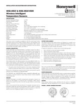
2.3: Specifications...................................................................................................................................................................................................10
2.3.1: Environmental Specifications...............................................................................................................................................................11
2.4: Magnet Sensors................................................................................................................................................................................................11
2.4.1: Profile Magnetic Sensor .......................................................................................................................................................................11
2.4.2: Mesh Formation Magnetic Sensor........................................................................................................................................................11
2.5: LED Indicators.................................................................................................................................................................................................11
2.6: Installing the Gateway.....................................................................................................................................................................................11
2.6.1: Before Installing ...................................................................................................................................................................................11
2.7: Mounting and Wiring.......................................................................................................................................................................................12
2.7.1: Mounting...............................................................................................................................................................................................12
2.7.2: Wiring...................................................................................................................................................................................................13
2.7.3: Gateway Powered by the SLC..............................................................................................................................................................14
2.7.4: Gateway Powered by an External, Regulated +24VDC Source...........................................................................................................14
2.8: Configuration and Programming.....................................................................................................................................................................15
2.8.1: Configuration and Programming Without Using SWIFT Tools ..........................................................................................................15
Create a New Profile...............................................................................................................................................................................15
Assign a Previously Created Profile Using a Distributor .......................................................................................................................16
Remove a Profile ....................................................................................................................................................................................16
Create a Mesh Network ..........................................................................................................................................................................16
2.8.2: Configuration and Programming Using SWIFT Tools ........................................................................................................................16
Assign a Profile.......................................................................................................................................................................................16
Remove a Profile ....................................................................................................................................................................................17
Create a Mesh Network ..........................................................................................................................................................................18
2.8.3: Profile Distribution...............................................................................................................................................................................19
After Creating a Profile...........................................................................................................................................................................19
Activating the Profile Magnetic Sensor..................................................................................................................................................19
2.8.4: SLC Configuration................................................................................................................................................................................19
2.9: Operations........................................................................................................................................................................................................20
2.9.1: Modes of Operation..............................................................................................................................................................................20
Start-up Mode .........................................................................................................................................................................................20
Factory Default Mode.............................................................................................................................................................................20
Profile Configured ..................................................................................................................................................................................20
Mesh Formation......................................................................................................................................................................................21
Initial Mesh Restructuring Mode............................................................................................................................................................21
Normal Mode..........................................................................................................................................................................................21
Rescue Mode...........................................................................................................................................................................................21
Mesh Restructuring Mode ......................................................................................................................................................................21
Bootloader Mode ....................................................................................................................................................................................21
Mesh Upgrade.........................................................................................................................................................................................21
Neighboring Network Scan
........................
............................................................................................................................................21
2.9.2: LED Patterns.........................................................................................................................................................................................22
2.9.3: Lock/Unlock the Gateway....................................................................................................................................................................22
Lock/Unlock the Gateway Using SWIFT Tools.....................................................................................................................................22
Password Reset .......................................................................................................................................................................................23
2.9.4: Weak Link Trouble Reporting..............................................................................................................................................................23
Disable Trouble Reporting at the Gateway Using SWIFT Tools...........................................................................................................23
2.9.5: Collapse Network Command................................................................................................................................................................24
Collapse Mesh Network Using SWIFT Tools........................................................................................................................................24
2.9.6: Silence Network Command..................................................................................................................................................................25
1.6: Cybersecurity Recommendations.........................................................................................................................................................................9

6 SWIFT® Smart Wireless Integrated Fire Technology Manual — P/N LS10036-000SK-E:C 8/28/2018
Table of Contents
Silence Mesh Network Using SWIFT Tools ..........................................................................................................................................25
2.9.7: Maximum of Four Overlapping Wireless Sensor Networks ................................................................................................................26
2.9.8: Activation of Wireless Output Devices................................................................................................................................................26
2.9.9: Avoiding RF Interference.....................................................................................................................................................................26
2.9.10: Trouble Messages...............................................................................................................................................................................26
2.9.11: Distributed Firmware Updates............................................................................................................................................................27
Section 3: Wireless Devices........................................................................................................................................... 28
3.1: Description.......................................................................................................................................................................................................28
3.2: Agency Approvals............................................................................................................................................................................................29
3.2.1: FCC.......................................................................................................................................................................................................29
3.2.2: Federal Institute of Telecommunications .............................................................................................................................................29
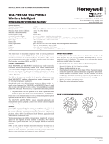
3.3: Specifications...................................................................................................................................................................................................30
3.4: Installing, Mounting, and Wiring Devices.......................................................................................................................................................30
3.4.1: Batteries................................................................................................................................................................................................30
3.5: Configuration and Programming.....................................................................................................................................................................30
3.5.1: Assigning Profiles.................................................................................................................................................................................30
Assigning a Profile to a Device (Detector or Module) Using a Gateway or Distributor........................................................................30
Assigning a Profile Using SWIFT Tools................................................................................................................................................32
3.5.2: Distributor Mode ..................................................................................................................................................................................32
Converting a Device into a Distributor...................................................................................................................................................32
Converting a Distributor Back into a Device..........................................................................................................................................33
3.5.3: Mesh Formation....................................................................................................................................................................................33
Repeater ..................................................................................................................................................................................................33
3.5.4: Restoring a Device to Factory Default .................................................................................................................................................33
Removing Profiles Without Using SWIFT Tools...................................................................................................................................33
Removing a Profile Using SWIFT Tools ...............................................................................................................................................33
3.6: Device Operations ...........................................................................................................................................................................................34
3.6.1: Modes of Operation..............................................................................................................................................................................34
Factory Default Mode.............................................................................................................................................................................34
Site Survey Mode....................................................................................................................................................................................34
Profile Assigned Mode ...........................................................................................................................................................................34
Bootloader Mode ....................................................................................................................................................................................34
Distributor Mode.....................................................................................................................................................................................35
Mesh Participant Modes .........................................................................................................................................................................35
3.6.2: LED Indicators......................................................................................................................................................................................35
3.6.3: Trouble Conditions...............................................................................................................................................................................35
Trouble Conditions with Fire Protection................................................................................................................................................35
Trouble States without Fire Protection...................................................................................................................................................36
Section 4: W-SYNC Wireless Synchronization Module ............................................................................................... 37
4.1: Description.......................................................................................................................................................................................................37
4.2: Wiring ..............................................................................................................................................................................................................37
4.2.1: FACP ....................................................................................................................................................................................................37
4.2.2: HPFF8/HPFF12 NAC Expander ..........................................................................................................................................................38
Section 5: W-USB Adapter.............................................................................................................................................. 39
5.1: Introduction......................................................................................................................................................................................................39
5.2: Agency Approvals...........................................................................................................................................................................................39
5.2.1: FCC.......................................................................................................................................................................................................39
5.2.2: Federal Institute of Telecommunications .............................................................................................................................................39
5.3: Specifications...................................................................................................................................................................................................40
5.3.1: Electrical Specifications .......................................................................................................................................................................40
5.3.2: Serial Communication Specification....................................................................................................................................................40
5.3.3: Mechanical Specifications....................................................................................................................................................................40
5.3.4: Environmental Specifications...............................................................................................................................................................40
5.4: Driver Installation............................................................................................................................................................................................40
Appendix A: SWIFT Tools............................................................................................................................................... 44
A.1: Description......................................................................................................................................................................................................44
A.2: Launching SWIFT Tools.................................................................................................................................................................................44
A.2.1: Creating a New Jobsite ........................................................................................................................................................................44
A.2.2: Opening an Existing Jobsite ................................................................................................................................................................45
A.3: Connecting to the Gateway.............................................................................................................................................................................45

SWIFT® Smart Wireless Integrated Fire Technology Manual — P/N LS10036-000SK-E:C 8/28/2018 7
Table of Contents
A.3.1: Accessing a Locked Gateway..............................................................................................................................................................45
A.3.2: Creating a New Password for a Gateway ............................................................................................................................................45
Appendix B: Site Survey................................................................................................................................................. 46
B.1: Conduct a Site Survey.....................................................................................................................................................................................46
B.1.1: Link Quality Test .................................................................................................................................................................................46
Basic Requirements of a Link Quality Test............................................................................................................................................46
Conduct a Link Quality Test...................................................................................................................................................................46
Results of a Link Quality Test ................................................................................................................................................................47
After a Link Quality Test........................................................................................................................................................................47
B.1.2: RF Scan Test ........................................................................................................................................................................................47
Conduct an RF Scan Test........................................................................................................................................................................47
Status of an RF Scan Test.......................................................................................................................................................................47
B.1.3: Retrieving Site Survey Results ............................................................................................................................................................48
Appendix C: Troubleshooting and Testing................................................................................................................... 49
C.1: Troubleshooting ..............................................................................................................................................................................................49
C.2: Testing the Gateway and Devices ...................................................................................................................................................................50
C.2.1: Testing LED Indicators........................................................................................................................................................................50
C.3: Testing the Wireless Network .........................................................................................................................................................................50
C.3.1: Network Topology...............................................................................................................................................................................51
Parent-Child Devices..............................................................................................................................................................................51
Orphan Devices.......................................................................................................................................................................................51
Class A Compliance................................................................................................................................................................................51
C.3.2: History Events......................................................................................................................................................................................51
C.3.3: Network Snapshots ..............................................................................................................................................................................51
C.3.4: Network Statistics ................................................................................................................................................................................51
C.3.5: Device Attributes .................................................................................................................................................................................51
Appendix D: LED Indicators........................................................................................................................................... 53
Appendix E: Firmware Upgrade/Downgrade Instructions........................................................................................... 58
E.1: W-USB Adapter Upgrade Procedure...............................................................................................................................................................58
E.2: Mesh Network Firmware Upgrade/Downgrade Procedure.............................................................................................................................59
E.3: Device and Gateway Firmware Upgrade/Downgrade Procedure ...................................................................................................................59
Index................................................................................................................................................................................. 61

8 SWIFT® Smart Wireless Integrated Fire Technology Manual — P/N LS10036-000SK-E:C 8/28/2018
Section 1: Overview
1.1 Purpose
The SWIFT® Network Manual provides an overview of the following:
• Wireless fire alarm system
• Instructions for installing and configuring the wireless devices
• Information on monitoring the status of the wireless devices
• Removal and replacement procedures of the Wireless Gateway
• Testing, maintenance, and firmware upgrade information of the Wireless Gateway
1.2 Assumed Knowledge
This document is created with the assumption that all users are familiar with working on a PC and laptop for configuration purposes.
Installers should be familiar with the fire alarm and related service standards. The terminology and level of details of this document
reflect this assumption.
1.3 Additional References
The table below provides a list of documents referenced in this manual, as well as documents for selected other compatible devices.
1.4 About the Mesh Network
Use of these products in combination with non-Honeywell products in a wireless mesh network, or to access, monitor, or control devices
in a wireless mesh network via the internet or another external wide area network, may require a separate license from Sipco, LLC. For
more information, contact Sipco, LLC or IntusIQ (Ipco), LLC at 8215 Roswell Rd, Building 900, Suite 950. Atlanta, GA 30350, or at
www.sipcollc.com or www.intusiq.com.
6820/6820EVS Fire Alarm Control Panel LS10144-001SK-E
6808 Fire Alarm Control Panel LS10146-001SK-E
6700 Fire Alarm Control Panel LS10146-001SK-E
WSK-PHOTO Wireless Photo Detector with 4” Base I56-4269
WSK-PHOTO-T Wireless Photo/Heat Detector with 4” Base I56-4269
WSK-HEAT-ROR Wireless Rate Of Rise Heat Detector with 4” Base I56-4270
WSK-HEAT Wireless Fixed Heat Detector with 4” Base I56-4270
WSK-MONITOR Wireless Monitor Module I56-4271
WSK-RELAY Wireless Relay Module I56-4272
WSK-PULL-DA Wireless Pullstation I56-6563
SWIFT Wireless AV Bases I56-6517
W-SYNC Wireless Sync Module I56-6518
MDL3 Sync Module I56-3157
HPFF8 NAC Expander 53499
HPFF12 NAC Expander 53576

SWIFT® Smart Wireless Integrated Fire Technology Manual — P/N LS10036-000SK-E:C 8/28/2018 9
Abbreviations Overview
1.5 Abbreviations
The following table lists the abbreviations and their definitions used in this manual.
Abbreviation Definition
AHJ Authority Having Jurisdiction
ANSI American National Standards Institute
dBm Units of RF power (0dBm = 1mW)
FACP Fire Alarm Control Panel
FCC Federal Communications Commission
ISM Band Industrial, Scientific and Medical Radio Bands
LCD Liquid Crystal Display
LED Light Emitting Diode
mA Milliampere
MHz Megahertz
NFPA National Fire Protection Association
PC Personal Computer
RF Radio Frequency
WSK-WGI Wireless Gateway
SLC Signaling Line Circuit
UI User Interface
UL Underwriters Laboratories
1.6 Cybersecurity Recommendations
• When using SWIFT Tools to update the firmware of the gateway or devices, ensure updates are performed in a secure location
where no eavesdropping on the wireless signals is possible.
• Ensure the PC running SWIFT Tools has full disk encryption. Full encryption of any backed-up data is also recommended.
• The wireless gateway should be secured in a location which is only accessible to authorized personnel.
• When any SWIFT gateway or device is decommissioned from service, return the equipment to the factory default state.

10 SWIFT® Smart Wireless Integrated Fire Technology Manual — P/N LS10036-000SK-E:C 8/28/2018
Section 2: WSK-WGI Wireless System Gateway
2.1 Description
The WSK-WGI is a device in a wireless fire system that acts as a bridge between fire alarm control panels (FACPs) and wireless fire
devices. All wireless fire devices communicate with the gateway over the wireless network formed by the devices and the gateway.
The gateway is powered by either the SLC loop or by any external +24VDC UL listed power supply. The gateway uses the SK protocol
on the SLC to communicate with the panel and a proprietary wireless protocol to communicate with wireless fire devices. The following
graphic is an illustration of the components of the SWIFT Network.
2.2 Agency Approvals
2.2.1 FCC
This device complies with part 15 of the FCC Rules. Operation is subject to the following two conditions:
1. This device may not cause harmful interference, and
2. This device must accept any interference received, including interference that may cause undesired operation.
3. FCC ID: PV3WFSGW
2.2.2 Federal Institute of Telecommunications
This device utilizes the Honeywell915 rev A radio module and complies with IFETEL standard(s).
IFT: RCPHOSW14-1983
2.3 Specifications
Following are the specifications of the wireless gateway.
Figure 2.1 SWIFT Network
FACP
SLC
wired SLC devices
WSK-WGI
Gateway
wireless mesh
network
SWIFT
Tools
W-USB
!
WARNING: DO NOT MAKE CHANGES TO THE EQUIPMENT
CHANGES OR MODIFICATIONS NOT EXPRESSLY APPROVED BY THE MANUFACTURER COULD VOID THE USER’S
AUTHORITY TO OPERATE THE EQUIPMENT.
Specifications Data
External Supply Electrical Ratings 18V-30V
SLC Electrical Ratings 15V-30V
Maximum current when using the external supply 40mA
Maximum current when using the SLC power supply 24mA
Maximum SLC Resistance 50Ω
Minimum signal strength level needed at the receiver for a primary path with weak
link trouble reporting enabled.
-55dBm

SWIFT® Smart Wireless Integrated Fire Technology Manual — P/N LS10036-000SK-E:C 8/28/2018 11
Magnet Sensors WSK-WGI Wireless System Gateway
2.3.1 Environmental Specifications
2.4 Magnet Sensors
Magnets must have a holding strength of 10 lbs or greater. Use either the north or south pole of the magnet to activate sensors.
2.4.1 Profile Magnetic Sensor
The profile magnetic sensor (refer to Figure 2.2) is used to create a unique profile upon start-up. It can also be used to start profile distri-
bution for a gateway that contains a profile. The LED next to the profile magnet sensor turns on green for ½ a second when the sensor is
activated.
2.4.2 Mesh Formation Magnetic Sensor
The mesh formation magnetic sensor (refer to Figure 2.2) transitions the gateway in and out of mesh formation mode. The initial activa-
tion of the sensor puts the gateway in mesh formation mode (as long as it contains a profile). A subsequent activation of the magnetic
sensor transitions the gateway out of mesh formation and into the initial mesh restructuring and normal mode. The gateway can be
placed back into mesh formation mode by activating the magnet sensor once again. The LED next to the profile magnet sensor turns on
green for ½ a second when the sensor is activated.
The Mesh formation magnetic sensor can also be used to create a profile on start-up for a gateway that does not already contain a profile.
2.5 LED Indicators
The two LEDs on the gateway blink in the same pattern to allow the LED to be viewed from any angle. LED patterns are explained in
Appendix D.
2.6 Installing the Gateway
2.6.1 Before Installing
Choose a location for the gateway that is clean, dry, and vibration-free. The area should be readily accessible with sufficient room to eas-
ily install and maintain the gateway. Metal obstructions impede the radio frequency communication and should be avoided. Carefully
unpack the system and inspect for shipping damage if any. All wiring must comply with the national and local codes for fire alarm sys-
tems.
Minimum signal strength level needed at the receiver for a secondary path or
primary path with weak link trouble reporting disabled.
Must be 18 dBm higher than the noise
floor down to a minimum of -80dBm
1
Maximum ambient noise level -85dBm
1
Maximum RF Power Output +17dBm (Tx power level without antenna)
Radio Frequency Lower ISM Band (902 - 928MHz).
1 Ensure that the primary path signal strength level is within recommended guidelines to assure proper communication in the
mesh network.
System Operating Temperature Storage Temperature Humidity
Gateway 0°C-49°C / 32°F-120°F -10°C- 60°C / 14°F-140°F 10 to 93% RH, Non-condensing
Figure 2.2 LEDs and Magnetic Sensors on the WSK-WGI
LEDs
Mesh
Formation
Magnetic
Sensor
Profile
Magnetic
Sensor
cover.wmf

12 SWIFT® Smart Wireless Integrated Fire Technology Manual — P/N LS10036-000SK-E:C 8/28/2018
WSK-WGI Wireless System Gateway Mounting and Wiring
2.7 Mounting and Wiring
2.7.1 Mounting
The gateway has two major pieces, the cover and the mounting plate. The mounting plate is mounted to the wall or ceiling, and field wir-
ing is connected to it. The cover contains the printed circuit board and is fastened to the mounting plate once the wiring is completed.
Mount the mounting plate directly to an electrical box on the ceiling or wall. The plate mounts directly to a 4˝ square (with and without
plaster ring), 4˝ octagon, 3 1/2˝octagon, single gang or double gang junction boxes. If an electrical box is not available, the mounting
plate can be mounted to any flat surface and the wiring can be connected via the knockout points in the mounting plate.
To mount the gateway:
1. Pull the wiring through the opening in the mounting plate.
2. Mount the mounting plate to the junction box or ceiling. See Figure 2.3 below.
3. Connect field wiring to the terminals, as described in Section 2.7.2.
4. Connect necessary jumpers where applicable, as described in Section 2.7.3.
5. To mount the cover, align the locating pins on the cover to the corresponding slots in the mounting plate. See Figure 2.4.
6. Secure the cover by tightening the mounting screws.
!
WARNING: FORMEX SHEET
ENSURE THAT THE FORMEX SHEET INSIDE THE GATEWAY IS NOT REMOVED OR TAMPERED WHILE INSTALLING
OR CLEANING.
Figure 2.3 Mounting Plate for Wireless Gateway
2.2.wmf
locating pin
locating pin
locating pin

SWIFT® Smart Wireless Integrated Fire Technology Manual — P/N LS10036-000SK-E:C 8/28/2018 13
Mounting and Wiring WSK-WGI Wireless System Gateway
2.7.2 Wiring
• All wiring must be installed in compliance with the National Electrical Code and the local codes having jurisdiction.
• 12-18 AWG is recommended.
For wiring connections:
1. Strip about 3/8” of insulation from the end of the wire.
2. Slide the stripped end of the wire under the appropriate terminal and tighten the screw.
Figure 2.4 Attaching Cover to Mounting Plate
2.3.wmf
locating pin
locating pin
locating pin
NOTE: Do not loop the wire under the screw terminals.
Figure 2.5 WSK-WGI Mounting Plate - Terminal Layout
A7 - SLC Out+/In+
A6 - SLC In+/Out +
A5 - SLC- (Common)
A4 - SLC Power Select 2
A3 - Power +24VDC
A2 - Power Ground
A1 - SLC Power Select 1
2.4.wmf

14 SWIFT® Smart Wireless Integrated Fire Technology Manual — P/N LS10036-000SK-E:C 8/28/2018
WSK-WGI Wireless System Gateway Mounting and Wiring
2.7.3 Gateway Powered by the SLC
To power the gateway using the signaling line circuit, connect the gateway as described in the table and graphic below:
The gateway provides isolation of short circuits on the SLC in Class A (Style 6) installations. SLC connections are power-limited by the
panel. An interruption in the SLC that causes a loss of power at the gateway for more than 100ms may result in a trouble condition and
loss of fire protection provided by the wireless devices for approximately 15 minutes. Use of an external +24V power source (not SLC
power) is recommended for installations that require fire protection in the presence of short circuits, including Class A applications and
applications that use isolator modules.
2.7.4 Gateway Powered by an External, Regulated +24VDC Source
To power the gateway using an external, regulated +24VDC source, connect the gateway as described in the table and drawing below.
Terminal
Pins
Description
A5 and A7 SLC - (Common) & SLC Output +
A5 and A6 SLC - (Common) & SLC Input +
A4 and A5 Jumper selection to enable power from the SLC supply. (Insert Jumper when using SLC power.)
A3 Unused
A1 and A2 Jumper selection to enable power from the SLC supply. (Insert Jumper when using SLC power.)
+
+
-
-
Figure 2.6 Wiring Connections: WSK-WGI Powered by the SLC
SLC out to next device (Class B)
or SLC return to FACP (Class A)
SLC in from FACP/device
jumpers
2.5.wmf
NOTE: Use of the same wire gauge is recommended if there are multiple connections to the same terminal.
Terminal Pins Devices Powered
A5 & A7 SLC Output
A5 & A6 SLC Input
A4 Unused
A2 & A3 +24VDC input. Voltage range from +18VDC to +30VDC.
Use only power-limited device circuits.
A1 Unused

SWIFT® Smart Wireless Integrated Fire Technology Manual — P/N LS10036-000SK-E:C 8/28/2018 15
Configuration and Programming WSK-WGI Wireless System Gateway
The gateway provides isolation of short circuits of the SLC in Class A (Style 6) installations. SLC connections are power-limited by the
panel. +24VDC must be power-limited by the source.
2.8 Configuration and Programming
To successfully configure and/or program the gateway:
1. Create a profile. A profile binds a gateway and the devices in a mesh network together. The profile will contain a mesh ID that is
used when forming the associations. All devices, including the gateway, require a common profile.
2. Distribute the profile. Distribute the profile to every device that will be a part of the mesh. This will enable all the devices that have
that profile to form associative links when the mesh is formed.
3. Form the mesh. The mesh cannot be formed until the profile is assigned to the gateway and distributed to its devices.
These steps may be performed with or without using SWIFT Tools.
2.8.1 Configuration and Programming Without Using SWIFT Tools
This section explains the configuration of the gateway using only a magnet and a screw driver. For configuration instructions using
SWIFT Tools, refer to Section 2.8.2.
There are two ways to provide a gateway with a profile without using SWIFT Tools.
Create a new profile using the gateway.
Assign a previously created profile to the gateway using a distributor.
Create a New Profile
To create a unique profile in the gateway without using SWIFT Tools:
1. Start with the gateway powered off. Be sure that the gateway is unlocked. New gateways are defaulted in the unlocked condition,
otherwise the gateway will need to be unlocked using SWIFT Tools. The profile creation process is performed during start-up.
2. Power on the gateway using SLC power or external +24V. Refer to Sections 2.7.3 and 2.7.4 for more information.
3. Ensure that the gateway is in the factory default state. If the gateway is in the factory default state, both the LEDs on the gateway
will double blink red every second for ten seconds. If the LEDs are yellow, refer to “Remove a Profile” on page 16.
4. Activate either magnetic sensor with a magnet within ten seconds of starting up the gateway while the double red blink is active on
the gateway. Refer to Section 2.4, “Magnet Sensors” for further information on activating magnetic sensors. The LED next to the
magnetic sensor emits a red light for one second when it is activated. If the ten second window is missed, power down the gateway
and repeat the process starting at step 1.
A profile has been created successfully. The LEDs on the gateway will light green and stay on steady for ten seconds. The profile has
been created containing a mesh ID. You will be prompted to create a password when trying to access the gateway through SWIFT Tools.
+
+
-
-
+
-
Figure 2.7 Wiring Connections: WSK-WGI Powered by an External, Regulated +24VDC Source
SLC in from FACP/device
External +24VDC Power
SLC out to next device (Class B)
or SLC return to FACP (Class A)
2.6.wmf
NOTE: It is recommended to use the same wire gauge if there are multiple connections to the same terminal.

16 SWIFT® Smart Wireless Integrated Fire Technology Manual — P/N LS10036-000SK-E:C 8/28/2018
WSK-WGI Wireless System Gateway Configuration and Programming
Immediately after successful profile creation, the gateway starts the profile distribution mode. Refer to Section 2.8.3 for further informa-
tion on profile distribution mode.
Assign a Previously Created Profile Using a Distributor
Instead of creating a new profile, an existing profile can be distributed by a device with an existing profile. To distribute the existing pro-
file:
1. Ensure that the gateway or other mesh device with the profile is set for distribution. Refer to Section 2.8.3, “Profile Distribution” or
Section 3.5.2, “Distributor Mode”.
2. Bring the profile distributor within 20 feet of the gateway.
3. 10 seconds after the initial start-up, the LEDs on the gateway switch from a double red blink to a single red blink. The single red
blink indicated the gateway is ready.
4. Use a magnet to activate either of the magnetic sensors. The LED will blink a single red every half-second indicating that it is
searching for a profile.
When the profile is successfully received from the distributor, the LEDs on the gateway will turn on green steady for five seconds.
Remove a Profile
To remove a profile from a gateway:
1. Start with the gateway powered off. The process is performed during start-up.
2. Power on the gateway using SLC power or external +24V. Refer to Sections 2.7.3 and 2.7.4 for more information.
3. Verify the gateway is in the profile modification state. The gateway is in the profile modification state when both the LEDs on the
gateway double blink yellow every second for ten seconds.
4. Activate both magnetic sensors on the gateway within ten seconds of start-up while the double yellow blink is active. If the ten
second window is missed, power down the gateway and repeat the process starting at step 1.
The LEDs on the gateway will blink green every second for five seconds indicating that the profile is removed.
Create a Mesh Network
The gateway communicates with all devices in range that have a common profile and establishes communication links with all the
devices. This creates a mesh network. Once a device joins the mesh, that device acts as a repeater for devices out of the range of the gate-
way. All devices must be within 20 feet of the gateway prior to initiating the mesh formation. The mesh formation is initiated by the
gateway upon user activation and terminated by the gateway when all possible devices join the network or when terminated by the user.
To form a mesh network, ensure that the gateway is powered on and contains a profile. (Refer to Section 2.5 on page 11 for information
on how the gateway indicates its status). Activate the “Mesh Formation” magnet sensor on the gateway. Refer to Figure 2.2 for sensor
location.
The gateway will then transition to the mesh formation mode and establish communication with all the devices containing a common
profile. The blink pattern on the gateway indicates that it is in mesh formation mode. At this stage, both the LEDs on the gateway will
blink twice every 7 seconds.
• The first blink is green and the second blink is red when the gateway is acting as a profile distributor and forming the mesh.
• The first blink is green and the second blink is yellow when the gateway is only forming the mesh.
Mesh formation typically takes one minute for each device in the mesh. Mesh formation automatically terminates 10 minutes after the
last device joins the mesh. Mesh formation can be terminated manually by the user by again activating the mesh formation magnetic sen-
sor.
Once the mesh formation is complete, the network automatically transitions to restructure the mesh. For operating instructions, refer to
Section 2.9, “Operations”.
2.8.2 Configuration and Programming Using SWIFT Tools
Assign a Profile
To assign a profile to the gateway using SWIFT Tools:
1. Connect the W-USB device to your laptop. For more information on the W-USB adapter, refer to Section 5, “W-USB Adapter”, on
page 39.
2. Launch SWIFT Tools. Refer to Appendix A for more information.
3. From the Home Screen, select the Create Mesh Network function.
4. Create a new profile or Import an existing profile as required.
NOTE: The Gateway is not visible in SWIFT Tools and will indicate a trouble if the SLC code is set to address “0”.
NOTE: If a gateway has been locked using SWIFT Tools, the ability to remove a profile using magnets is no longer available.

SWIFT® Smart Wireless Integrated Fire Technology Manual — P/N LS10036-000SK-E:C 8/28/2018 17
Configuration and Programming WSK-WGI Wireless System Gateway
5. Select and open the profile to be assigned to the gateway from the Name drop-down box in the Profile section.
6. Power on the gateway within approximately 20 feet of the laptop running SWIFT Tools.
7. Place devices within 20 feet of the laptop, with a minimum of 3 feet between each device.
8. Ensure that the Scan On selection box in the Communicator Window is checked.
9. Select the gateway from the Communicator Window on the right side of the Tools screen.
10. Click Assign.
The gateway is now included in the list of devices with a profile assigned. The LEDs on the gateway will turn on green for 10 seconds
after the profile has been received.
Remove a Profile
To remove a profile from a gateway using the SWIFT Tools application:
1. Connect the W-USB adapter to your laptop. For more information on the W-USB device, refer to Section 5, “W-USB Adapter”, on
page 39.
2. Launch SWIFT Tools. Refer to Appendix A, “SWIFT Tools” for more information on launching the SWIFT Tools application.
3. From the Home Screen, select the Site Survey, Create Mesh Network, or Diagnostics function.
4. Click Operations and select Set device to factory default.
5. The Reset Devices screen appears, displaying the gateway and other devices that have a profile assigned. Click to select the
gateway and click Reset Device to remove the profile.
Figure 2.8 Selecting a Profile
assignprofile_select.jpg
Figure 2.9 Gateway Selection
communicator_show_4,jpg
Figure 2.10 Assign a Profile
assignprofile_confirm2.jpg
Figure 2.11 Operations Menu
operations.jpg

18 SWIFT® Smart Wireless Integrated Fire Technology Manual — P/N LS10036-000SK-E:C 8/28/2018
WSK-WGI Wireless System Gateway Configuration and Programming
The profile is removed and the gateway is reset to factory default state.
Create a Mesh Network
To create a mesh network using the SWIFT Tools, perform the following steps.
1. Connect the W-USB device to your laptop. For more information on the W-USB adapter, refer to Section 5, “W-USB Adapter”, on
page 39.
2. Launch SWIFT Tools. Refer to Appendix A for more information.
3. From the Home Screen, select the Create Mesh Network function.
4. Proceed to the second step of the Create Mesh Network function by clicking the arrow marked Next at the bottom of the screen.
5. Click to select the desired gateway displayed in the Gateways in Range table.
6. The Enter password for Gateway screen is displayed. Enter the password and follow the on-screen instructions. Note that, once
accessed, the login will be valid for only 30 minutes. For additional information, refer to “Lock/Unlock the Gateway” on page 22.
7. Click Start Mesh Formation.
8. A message is displayed. Click Yes to proceed or click No to cancel.
9. The Mesh Formation screen is displayed indicating that the mesh formation is in progress.
• The Progress Status column indicates progress status of the selected gateway.
• The No. of Devices Joined column indicates the number of devices that are in the mesh network including the gateway.
• The Total Device Count Expected column indicates the number of devices expected to join including the gateway. This field is
editable. Click in to the field to edit the number of device count expected.
resetdevices.jpg
Figure 2.12 Reset Devices Screen
meshoptools.png
Figure 2.13 Gateways in Range Table

SWIFT® Smart Wireless Integrated Fire Technology Manual — P/N LS10036-000SK-E:C 8/28/2018 19
Configuration and Programming WSK-WGI Wireless System Gateway
10. Once the expected count of devices have joined the mesh, a message is displayed to show that the Mesh formation is complete and
an option is given to choose to start mesh restructuring immediately or wait for any other devices to join.
11. Start Mesh Restructuring (by either waiting or clicking Start). Once Restructuring is initiated, the progress displays. When Mesh
Restructuring is complete, the following success message is shown. For further operating instructions, refer to Section 2.9,
“Operations”.
2.8.3 Profile Distribution
There are two ways to initiate profile distribution from the gateway:
• Automatically after creating a profile if the profile was not created by SWIFT Tools
• Activating the profile-creating magnetic sensor when the gateway has a profile
After Creating a Profile
Profile distribution is automatically enabled from the gateway after creating a profile using either magnetic sensor upon the gateway’s
start-up. The profile distribution automatically terminates after 10 minutes.
Activating the Profile Magnetic Sensor
Activating the profile magnetic sensor (refer to Figure 2.2) when the gateway has a profile will put the gateway in a mode of distributing
the profile to any device that requests a profile. The gateway’s LED pattern will be altered when it is distributing a profile for easy iden-
tification. Profile distribution will automatically terminate after 10 minutes. For more information on gateway LED patterns, refer to
Section 2.5 on page 11.
2.8.4 SLC Configuration
The gateway:
communicates with the control panel via the SLC.
is only compatible with Gateway firmware version 2.1 or higher.
Figure 2.14 Completed Mesh Formation Screen
startmeshformation5.jpg
Figure 2.15 Completed Restructuring Screen
meshrestruct_end.jpg

20 SWIFT® Smart Wireless Integrated Fire Technology Manual — P/N LS10036-000SK-E:C 8/28/2018
WSK-WGI Wireless System Gateway Operations
occupies one module SLC address. Set the address using the rotary dials on the gateway prior to installation.
The SLC point uses the following configuration parameters:
• Type Code Label: Wireless Gateway
A gateway does not initiate alarms but the point is used for event reporting.
2.9 Operations
2.9.1 Modes of Operation
Start-up Mode
Start-up mode is a temporary mode of operation. During start-up mode a profile can be created or removed. The start-up period lasts for
10 seconds. If a particular unit contains a profile, the LEDs double blink yellow every second. If the unit does not contain a profile, the
LEDs double blink red every second.
During start-up, the gateway does not provide fire protection nor does it respond to the FACP.
After start-up, the gateway proceeds to the factory default mode if no profile exists. In the presence of a profile, the gateway will pro-
ceed to mesh formation mode if it was previously part of a mesh network or normal mode if it was not previously part of a mesh net-
work.
Factory Default Mode
Factory default mode is the initial mode of the gateway. In this mode, the gateway and peripheral devices do not provide any fire protec-
tion. The gateway does not communicate with wireless detectors or modules in factory default mode. The only wireless communication
in factory default mode is between the gateway and SWIFT Tools. SWIFT Tools must be within 20 feet of the gateway for proper com-
munication. The gateway must be assigned a profile before continuing configuration.
The gateway reports a “NO PROFILE” trouble to the FACP. The gateway reports “Factory Default” to the communicator display of
SWIFT Tools.
Transitions back to Factory Default mode are not shown in the above diagram. However, any time the profile is removed from the gate-
way, it will return to Factory Default mode.
Profile Configured
The gateway enters the profile configured mode once a profile is assigned by SWIFT Tools or a distributor; or after creating a profile
using the magnetic sensor. Profile configured mode is a temporary mode before the gateway transitions to mesh formation or normal
mode.
TENS
8
9
10
11
12
13
14
15
0
1
2
3
4
5
6
7
ONES
8
9
0
1
2
3
4
5
6
7
Figure 2.16 Address Rotary Switches
SLC-setaddtph.wmf
NOTE: When a wireless relay, wireless AV base, or wireless sync module is in use, module device count must be limited to 109 modules
per loop. This includes wired and wireless modules that are on the same loop. The module address range must be within 1-109.
Figure 2.17 Gateway Modes Of Operation
Start-up
Factory
Default
Profile
Configured
Mesh
Formation
Initial Mesh
Restructuring
Normal Mode
Mesh
Restructuring
Rescue Mode
Fire Protection Provided
Neighboring
Network Scan
Mesh
Upgrade in
Progress
Mesh
Upgrade
Preparation
/