SILENT KNIGHT WSK-PULL-DA User manual
- Category
- Fire protection
- Type
- User manual

BEFORE INSTALLING
This pull station must be installed in compliance with the control panel sys-
tem installation manual, the SWIFT Wireless Gateway Manual, applicable
NFPA standards, national and local Fire codes and the requirements of the
AHJ (Authority Having Jurisdiction). Regular testing of the devices should be
done in accordance with the appropriate NFPA standards. Pull stations offer
maximum performance when installed in compliance with the National Fire
Protection Association (NFPA); see NFPA 72.
NOTICE: This manual should be left with the owner/user of this equipment.
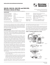
GENERAL DESCRIPTION
The WSK-PULL-DA wireless, addressable pull station is a UL38-compliant
dual-action manual pull station with a key-lock reset feature intended for
use with a wireless gateway or wireless fire alarm control panel (FACP). (See
Figure 1). It provides Silent Knight panels one addressable alarm initiating in-
put. The device communicates through a robust, bi-directional mesh network
to the gateway and/or FACP. Rotary dial switches are provided for setting the
pull station’s address. (See Figure 2.) Operating instructions are molded into
the pull station handle along with Braille text. The wireless pull station meets
the Americans with Disabilities Act Accessibility Guidelines (ADAAG) controls
and operating mechanisms guidelines (section 4.1.3[13]), the Americans with
Disabilities Act (ADA) requirement for a 5 lb. maximum pull force to activate
the pull station and conforms to ANSI/UL Standard 38.
Panels offer different feature sets across the various models. As a result, cer-
tain features may be available on some control panels, but not on others. The
possible feature sets available with the wireless pull station include:
• An LED on the wireless pull station is controlled by the panel to indicate
device status. Operational modes include red, green and amber colors in
various solid or blink patterns.
COMPATIBILITY REQUIREMENTS
To ensure proper operation, this module shall be connected to a compatible
Silent Knight system control panel (list available from Silent Knight).
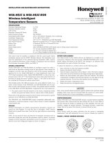
FIGURE 1. WIRELESS MANUAL PULL STATION
C2039-00
BATTERY DOOR
The battery door includes a magnet for activation and tamper resistance. (See
Figure 2.) The battery door magnet activates communication to the panel,
therefore, the battery door must be installed and closed for the pull station
to work properly. The magnet also activates a tamper fault at the panel if the
battery door is opened. Do NOT remove this magnet.
BATTERY REPLACEMENT
Low battery levels on the wireless devices are displayed as a trouble in the
FACP. Therefore when the message “TROUBLE BATTERY LOW” is displayed,
replace the battery in the device. This message is an indication that approxi-
mately one week of battery life remains.
To replace the batteries in a wireless device use the following steps:
1. Have 4 CR123A (or DL123A) batteries available.
2. Use the key to unlock and open the pull station door.
3. Open the battery compartment. (See Figure 2.)
4. Remove the used batteries and replace with new batteries. Batteries can be
inserted directly into the pull station or inserted as a set of 4 batteries pre-
loaded in a battery cartridge available from Silent Knight. (See Figure 2.)
The battery compartment and cartridge indicate the correct orientation of
the batteries. Carefully align the batteries with these markings, and do not
force them into place.
5. Close the battery compartment cover.
6. Close and lock the pull station door.
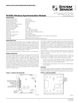
FIGURE 2. BATTERY INSTALLATION
Rotary Address Switches
Battery Compartment With Door Open
Battery Compartment Door in the Open (Down) Position
Battery
Magnet
Location
Battery Compartment Door in the Closed (Up) Position
C2041-00
Battery Cartridge
C2030-00
SPECIFICATIONS
Maximum Operating Voltage: 3.3 VDC
Maximum Current Draw: 5.0 mA (LED on)
Average Operating Current: 210 µA
Maximum Transmit RF Power: 17 dBm
Radio Frequency Range: 902-928 MHz
Temperature Range: 32°F to 120°F (0°C to 49°C)
Humidity: 10% to 93% Non-condensing
Battery Type: 4 Panasonic CR123A or 4 Duracell DL123A
Battery Life: 2 year minimum
Battery Replacement: Upon TROUBLE BATTERY LOW display and/or during annual maintenance
Dimensions: 5.6" (142 mm) H x 4.2" (107 mm) W x 2.1" (53 mm) D
Accessories: Battery Cartridge W-BATCART
WSK-PULL-DA Wireless Pull Station
I56-6563-000
INSTALLATION AND MAINTENANCE INSTRUCTIONS
12 Clintonville Road, Northford, CT 06472-1610
Phone: 203-484-7161 Fax: 203-484-7118
www.silentknight.com
12 Clintonville Road, Northford, CT 06472-1610
Phone: 203-484-7161 Fax: 203-484-7118
www.silentknight.com
1 I56-6563-000
11/06/2017

OPERATION
To activate the dual-action pull station:
Push in and pull down on the handle. The word ‘ACTIVATED’ appears after
the handle is pulled down. This will remain until the pull sta tion is reset.
To reset the pull station:
1. Insert the key into the lock and rotate 1/4 turn counterclockwise.
2. Open the door until the handle returns to normal.
3. Close and lock the door.
NOTE: Closing the door automatically resets the switch to the ‘Normal’ posi-
tion. Open ing the door will not activate or deactivate the alarm switch.
SPACING
Wireless technologies can exhibit communication disruption if devices are
spaced too close together. To avoid this form of disruption, SWIFT® devices
should not be placed closer than 2 feet (60 cm) apart without an intervening
structure. For specific information regarding pull station placement refer to
NFPA 72, ADAAG, and ADA.
MOUNTING
To mount the wireless pull station, attach the wireless pull station mounting
plate to a permanent structure. The mounting plate can be surface mounted.
To avoid interference with the wireless network metal electrical boxes are NOT
recommended. Do not detach the door of the pull station during installation.
The door of the pull station cannot be reattached to the main housing after the
pull station has been installed. Place the pull station onto the mounting plate
and secure by tightening all three (3) mounting screws inside the door of the
product housing using a #1 Phillips head screwdriver. (See Figure 3.)
NOTE: Do not attach the pull station to temporary structures such that the
placement could be altered.
FIGURE 3. DEVICE MOUNTING
Mounting
Screws
Mounting
Plate
C2020-00
LICENSING STATEMENT
Use of these products in combination with non-Honeywell products in a wireless mesh network, or to access, monitor or control devices in a wireless mesh nework via the internet
or another external wide area network, may require a separate license from Sipco, LLC. For more information, contact Sipco, LLC or Ipco, LLC at 8215 Roswell Rd., Building 900,
Suite 950, Atlanta, GA 303350, or at www.sipocollc.com or www.intusiq.com.
FCC STATEMENT
This device complies with part 15 of the FCC Rules. Operation is subject to the following two conditions:
1. This device may not cause harmful interference, and
2. This device must accept any interference received, including interference that may cause undesired operation.
2 I56-6563-000
©2017 Silent Knight. 11/06/2017
Silent Knight
®
and SWIFT
®
are registered trademarks of Honeywell International, Inc.
-
 1
1
-
 2
2


SILENT KNIGHT WSK-PULL-DA User manual
- Category
- Fire protection
- Type
- User manual
Ask a question and I''ll find the answer in the document
Finding information in a document is now easier with AI
Related papers
-
 SILENT KNIGHT SWIFT WSK-MONITOR User manual
-
 SILENT KNIGHT Silent Knight WSK-RELAY User manual
-
 SILENT KNIGHT SWIFT WSK-PHOTO User manual
-
 SILENT KNIGHT SWIFT Wireless Integrated Fire Technology Installation guide
-
 SILENT KNIGHT Swift User manual
-
 SILENT KNIGHT WSK-HEAT-ROR User manual
-
 SILENT KNIGHT 6808 User manual
-
 SILENT KNIGHT 6700 User manual
-
 SILENT KNIGHT WAV-CRL / WAV-CWL User manual
-
 SILENT KNIGHT W-SYNC Wireless Synchronization Module User manual


Other documents
-
Honeywell International Swift User manual
-
Notifier SWIFT Wireless User manual
-
Honeywell 5820XL User manual
-
 imin Swift 1 Series Smart POS Device User manual
-
Notifier NFS2-3030 Installation guide
-
 Audio Authority MR-2900 Installation guide
-
ADEMCO CFS8DL5808LP-1 User manual
-
-
System Sensor B200S-WH, B200S-IV Intelligent Sounder Base User manual
-

