Page is loading ...

MOUNTING
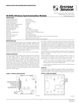
Mounts directly to 4-inch square electrical boxes (see Figure 2A). The box
must have a minimum depth of 2
1
/8 inches. Surface mounted electrical boxes
(SMB500) are available from System Sensor.
FIGURE 2. MODULE MOUNTING: FIGURE 2B:
C1075-00
M500DM Dual Monitor Module
INSTALLATION AND MAINTENANCE INSTRUCTIONS
3825 Ohio Avenue, St. Charles, Illinois 60174
1-800-SENSOR2, FAX: 630-377-6495
www.systemsensor.com
BEFORE INSTALLING
This information is included as a quick reference installation guide. Refer to
the control panel installation manual for detailed system information. If the
modules will be installed in an existing operational system, inform the opera-
tor and local authority that the system will be temporarily out of service. Dis-
connect power to the control panel before installing the modules.
NOTICE: This manual should be left with the owner/user of this equipment.
GENERAL DESCRIPTION
The Dual Monitor Module is intended for use in intelligent, two wire systems.
It provides two independent 2-wire initiating device circuits (IDC), at two sep-
arate, consecutive addresses. It is capable of monitoring normally open con-
tact fire alarm and supervisory devices, or either normally open or normally
closed security devices.
COMPATIBILITY REQUIREMENTS
To ensure proper operation, these modules shall be connected to listed com-
patible system control panels only.
FIGURE 1. CONTROLS AND INDICATORS:
C0917-01
SPECIFICATIONS
Normal Operating Voltage: 15 to 32 VDC
Maximum Current Draw: 6.4 mA (LED on)
Average Operating Current: 750 µA (LED flashing)
EOL Resistance: 47K Ohms
Maximium SLC wiring resistance: 40 Ohms
Maximum IDC wiring resistance: 1,500 Ohms
Maximum IDC Voltage: 11 Volts
Maximum IDC Current: 240µA
Temperature Range: 32°F to 120°F (0°C to 49°C)
Humidity: 10% to 93% Non-condensing
Dimensions: 4
1
/2 in H x 4.275 in W x 1.4 in D (Mounts to a 4-inch square by 2
1
/8-inch deep box.)
Accessories: SMB500 Electrical Box
I56-3869-002
1 I56-3869-002
03-11

THREE-YEAR LIMITED WARRANTY
System Sensor warrants its enclosed product to be free from defects in materials and
workmanship under normal use and service for a period of three years from date of
manufacture. System Sensor makes no other express warranty for the enclosed product.
No agent, representative, dealer, or employee of the Company has the authority to in
-
crease or alter the obligations or limitations of this Warranty. The Company’s obligation
of this Warranty shall be limited to the replacement of any part of the product which is
found to be defective in materials or workmanship under normal use and service during
the three year period commencing with the date of manufacture. After phoning System
Sensor’s toll free number 800-SENSOR2 (736-7672) for a Return Authorization number,
send defective units postage prepaid to: Honeywell, 12220 Rojas Drive, Suite 700, El Paso
TX 79936 USA. Please include a note describing the malfunction and suspected cause
of failure. The Company shall not be obligated to replace units which are found to be
defective because of damage, unreasonable use, modifications, or alterations occurring
after the date of manufacture. In no case shall the Company be liable for any consequen
-
tial or incidental damages for breach of this or any other Warranty, expressed or implied
whatsoever, even if the loss or damage is caused by the Company’s negligence or fault.
Some states do not allow the exclusion or limitation of incidental or consequential dam
-
ages, so the above limitation or exclusion may not apply to you. This Warranty gives you
specific legal rights, and you may also have other rights which vary from state to state.
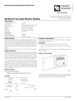
FIGURE 3. TYPICAL 2-WIRE INITIATING CIRCUIT CONFIGURATION, NFPA STYLE B:
C1074-07
FCC STATEMENT
This equipment has been tested and found to comply with the limits for a Class B digital device, pursuant to Part 15 of the FCC rules. These limits are designed to provide reasonable
protection against harmful interference. This equipment generates, uses, and can radiate radio frequency energy and, if not installed and used in accordance with the instruction
manual, may cause harmful interference to radio communications. Operation is subject to the following two conditions: (1) This device may not cause harmful radiation, and (2) this
device must accept any interference received, including interference that may cause undesired operation.
WIRING
NOTE: All wiring must conform to applicable local codes, ordinances, and
regulations. This module is intended for power limited wiring only.
1. Install module wiring in accordance with the job drawings and appropri-
ate wiring diagrams.
2. Set the address on the module per job drawings.
NOTE: Monitor module L (using terminals 6 and 7) responds at the ad-
dress set on the code switches. Monitor module H (using terminals 8 and
9) will automatically respond at the next higher address. For example, if
the code switches are set to 76, module L will respond at address 76 and
module H will respond at address 77. Use caution to avoid duplicate ad-
dressing of modules on the system.
3. Secure module to electrical box (supplied by installer), as shown in Fig-
ure 2.
H
L
TWO INITIA
TING DEVICE CIRCUITS (L&H), EACH
POWER LIMITED
TO 240 µA @ 11 VDC MAX.
UL
LISTED CONTACT CLOSURE DEVICES MAY
BE USED. DO NOT
MIX FIRE ALARM INITIATING,
SUPER
VISORY, OR SECURITY DEVICES ON THE
SAME INITIA
TING DEVICE CIRCUIT.
INST
ALL CONTACT CLOSURE DEVICES PER
MANUFACTURER’S INSTALLATION INSTRUCTIONS.
47k EOL
RESISTOR
47k EOL
RESISTOR
TO NEXT
DEVICE
(+)
(−)
(+)
(−)
(+)
(−)
FROM PANEL OR
PREVIOUS DEVICE
CONNECT MODULES TO LISTED
COMPATIBLE CONTROL PANELS ONLY
MONITOR L (TERMINALS 6 & 7) RESPONDS AT ADDRESS
SET ON CODE SWITCHES. MONITOR H (TERMINALS 8 &
9) RESPONDS AT NEXT HIGHER ADDRESS.
SIGNAL LINE CIRCUIT (SLC)
32 VDC MAX.
TWISTED PAIR IS RECOMMENDED
MONITOR
MODULE
ALL WIRING SHOWN IS
SUPERVISED AND POWER LIMITED
2 I56-3869-002
©2016 System Sensor. 03-11
/