Page is loading ...

This sensor must be installed in compliance with the control panel system
installation manual and the SWIFT Wireless Manual. The installation must
meet the requirements of the Authority Having Jurisdiction (AHJ). Sensors
offer maximum performance when installed in compliance with the National
Fire Protection Association (NFPA); see NFPA 72.
GENERAL DESCRIPTION
Models WSK-HEAT and WSK-HEAT-ROR are intelligent sensors that utilize a
state-of-the-art thermistor sensing circuit for fast response. These sensors are
designed to provide open area protection with 50 foot spacing capability as
approved by UL 521. Model WSK-HEAT is a fixed temperature sensor with
135°F fixed temperature alarm. Model WSK-HEAT-ROR is a rate-of-rise tem-
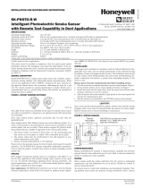
perature sensor with 135° F fixed temperature alarm. Rotary dial switches are
provided for setting the sensor’s address. (Figure 1). Two LEDs on the sensor
are controlled by the panel to indicate sensor status.
Silent Knight panels offer different features sets across different models. As a
result, certain features of the WSK-HEAT and WSK-HEAT-ROR may be avail-
able on some control panels, but not on others. The possible features available
in the WSK-HEAT and WSK-HEAT-ROR, if supported by the control panel are:
• The panel controls the LED operation on the sensor. Operational modes
include red, green and amber colors in various solid or blink patterns.
Please refer to the operation manual for the UL listed control panel for specific
operation of the WSK-HEAT and WSK-HEAT-ROR .
The WSK-HEAT and WSK-HEAT-ROR require compatible addressable com-
munications to function properly. Connect these sensors to listed-compatible
control panels only.
SPACING
Wireless technologies can exhibit communication disruption if devices are
spaced too close together. To avoid this form of disruption, SWIFT devices
should not be placed closer than 2 feet (60 cm) apart without an intervening
structure.
NOTE: Do not attach the base and detectors to temporary structures such as
removable ceiling tiles such that the placement could be altered. To prevent
changes in device placement, permanently secure the structure or mount the
detector across the ceiling panel support as shown in Figure 2.
I56-4270-000
INSTALLATION AND MAINTENANCE INSTRUCTIONS
SPECIFICATIONS
Maximum Operating Voltage: 3.3 VDC
Maximum Standby Current: 210µA
LED Current: 10 mA
Maximum Transmit RF Power: 17dBm
Radio Frequency Range: 902-928 MHz
Operating Humidity Range: 10% to 93% Relative Humidity, Non-condensing
Installation Temperature: 32°F to 100°F (0°C to 38°C)
Fixed Temperature Rating: 135°F (57°C ) WSK-HEAT and WSK-HEAT-ROR
Rate-of-Rise Detection: Responds to greater than 15°F/minute WSK-HEAT-ROR
Battery Type: 4 Panasonic CR123A or 4 Duracell DL123A
Battery Life: 2 year minimum
Battery Replacement: Upon TROUBLE BATTERY LOW display and/or during annual maintenance
Height: 2.4˝ (61 mm) installed in B501W Base
Diameter: 4.0˝ (102 mm) installed in B501W Base
Weight: 8.1 oz. (230 g) installed in B501W base with 4 batteries
BATTERY REPLACEMENT
Low battery levels on the wireless devices are displayed as a trouble on an
annunciator. Therefore when the message “TROUBLE BATTERY LOW” is dis-
played, replace the battery in the device. This message is an indication that
approximately one week of battery life remains.
To replace the batteries in a wireless device use the following steps:
1. Have 4 CR123A (or DL123A) batteries available
2. Remove the detector from the base.
3. Open the battery compartment refer to Figure 3. Note: The battery compart-
ment cover may be left attached at the hinges during battery replacement.
4. Remove the used batteries and replace with new batteries. The battery
compartment is designed such that the batteries can only align in the ap-
propriate direction. Do not force the batteries into the openings.
5. Replace the battery compartment cover.
6. Return the device to its original location.
CAUTION
Dust covers provide limited protection against airborne dust particles during
shipping. Dust covers must be removed before the sensors can sense smoke.
Remove sensors prior to heavy remodeling or construction.
TAMPER RESISTANCE
Models WSK-HEAT and WSK-HEAT-ROR include a tamper-resistant capability
that prevents their removal from the base without the use of a tool. Refer to
the base manual for details on making use of this capability. The base also
includes a magnet for tamper resistance. The magnet activates a supervisory
tamper fault at the panel if the detector is removed from the base.
TESTING
Before testing, notify the proper authorities that the system is undergoing
maintenance, and will temporarily be out of service. Disable the system to
TENS ONES
9
10
11
12
13
14
15
8
7
6
5
4
3
2
1
0
9
8
7
6
5
4
3
2
1
0
C0162-00
FIGURE 1. ROTARY ADDRESS SWITCHES:
12 Clintonville Road, Northford, CT 06472-1610
Phone: 203-484-7161 Fax: 203-484-7118
www.silentknight.com
WSK-HEAT & WSK-HEAT-ROR
Wireless Intelligent
Temperature Sensors
1 I56-4270-000
03-02

Disable the zone or system undergoing maintenance to prevent unwanted alarms.
It is recommended that the sensor be removed from its mounting base for
easier cleaning and that sensors be cleaned at least once a year. Use a vacuum
cleaner to remove dust from the sensing chamber (Figure 5).
SPECIAL NOTE REGARDING SMOKE DETECTOR GUARDS
Smoke detectors are not to be used with detector guards unless the combina-
tion has been evaluated and found suitable for that purpose.
BATTERY
COMPARTMENT
COVER
FIGURE 2. CEILING PANEL SUPPORT:
FIGURE 3. BATTERY COMPARTMENT:
prevent unwanted alarms.
All sensors must be tested after installation and periodically thereafter. Testing
methods must satisfy the Authority Having Jurisdiction (AHJ). Sensors offer max-
imum performance when tested and maintained in compliance with NFPA 72.
The sensor can be tested in the following ways:
A. Functional: Magnet Test (P/N M02-04-01 or M02-09-00)
1. Place the optional test magnet against the cover in the magnet test
area, as shown in Figure 4, to activate the test feature.
2. The LEDs should latch on within 10 seconds, indicating alarm and an-
nunciating the panel.
3. Reset the detector at the system control panel.
B. Direct Heat Method (Hair dryer of 1000 – 1500 watts).
1. From the side of the detector, direct the heat toward the sensor. Hold
the heat source about 6 inches (15 cm) away to prevent damage to the
cover during testing.
2. The LEDs on the detector should light when the temperature at the
detector reaches the alarm setpoint. If the LEDs fail to light, check the
power to the detector and the wiring in the detector base.
3. Reset the detector at the system control panel.
A sensor that fails any of these tests should be cleaned as described under
CLEANING, and retested. If the sensor fails after cleaning, it must be replaced
and returned for repair.
When testing is complete, restore the system to normal operation and notify
the proper authorities that the system is back in operation.
CLEANING
Before removing the detector, notify the proper authorities that the smoke de-
tector system is undergoing maintenance and will be temporarily out of service.
C2016-00
C1092-00
2 I56-4270-000
03-02

COVER
REMOVAL
TABS
SENSOR
COVER
SENSING
CHAMBER
WSK-HEAT &
WSK-HEAT- ROR
C2014-01
LED
TEST MAGNET
MARKER
LED
TEST
MAGNET
MARKER
FIGURE 5. DETECTOR COMPONENTS:
FIGURE 4. MAGNET TEST MARKERS:
C0152-00
FM CLASSIFICATION
RTI ratings are for installations which must comply with FM 3210.
WSK-HEAT RTI: FAST
WSK-HEAT-ROR RTI: V2-FAST
3 I56-4270-000
03-02

Please refer to insert for the Limitations of Fire Alarm Systems
This device complies with part 15 of the FCC Rules. Operation is subject to the following two conditions:
1. This device may not cause harmful interference, and
2. This device must accept any interference received, including interference that may cause undesired operation.
WARNING: Do not make changes to the equipment. Changes or modifications not expressly approved by the manufacturer could void the user’s authority to operate the equipment.
FCC STATEMENT
Use of these products in combination with non-Honeywell products in a wireless mesh
network, or to access, monitor or control devices in a wireless mesh nework via the inter-
net or another external wide area network, may require a separate license from Sipco, LLC.
For more information, contact Sipco, LLC or Ipco, LLC at 8215 Roswell Rd., Building 900,
Suite 950, Atlanta, GA 303350, or at www.sipocollc.com or www.intusiq.com.
LICENSING STATEMENT
4 I56-4270-000
©2017 Honeywell. 03-02
Silent Knigh
®
and Honeywell
®
are registered trademarks of Honeywell International, Inc.
/