Page is loading ...

E15 SPRAYER Operators Manual
KEE E15 Horticultural Sprayer Console
W117 V1.0

V 3.0 100903
Major Topic Heading
How to use this operator’s manual
As with any computer operated equipment, software and/or hardware is in many cases changed
and upgraded over the life of the equipment.
KEE Technologies software engineers are constantly working on software enhancements which
will provide you with many additional benefits and features in the future.
The EAGLE System will keep on evolving! ...to ultimately improve your ‘bottom line”!
KEE Technologies personnel have records of all changes implemented to your system with the
subsequent serial number.
When talking to KEE Technologies Support staff, always have this manual with you, as we may
ask you what version manual you are currently looking at to ensure we all talk the same
language. For this purpose all pages are coded as follows.
Page number Date when written Software version
Below is space provided to keep records of any software and hardware upgrades you may have
received.
The Software Version Number of the Eagle Console can be located when the console first powers
up. The File name which contains the Software version number will be displayed for about 2-3
seconds.
The name of the file will be on the last line, it will look like this.
KEE_HSC_1_0_13.HEX
Where: KEE_HSC_ -shows the type of software, is a KEE Horticultural Sprayer Complete.
1_0_13 - The software version number
HEX - Type of file.
Type of upgrade (software or hardware) Version Date Manual upgraded
KEE Eagle E15 Horticultural Sprayer
1.0.13 11/05
11/05

V1.86
V 1.86
3.0 SPRAYER SETUP MENU
3.1 SET THE PRESET RATE 1 20
3.2 SET THE PRESET RATE 2 20
3.3 MINIMUM FLOW HOLD 20
3.4 SET THE PRESET ROW WIDTH AND SECTIONS WIDTHS 21
3.5 SET THE LOW SPEED SHUT OFF 23
3.6 SET THE TANK VOLUME 23
3.7 APPLICATION MODE 23
3.8 SET THE WHEEL CALIBRATION FACTOR 24
3.8.1 SELECT SPEED SOURCE 25
3.8.2 AUTOMATIC WHEEL CALIBRATION 25
3.8.3 MANUAL ENTRY OF WHEEL FACTOR 25
3.9 SET THE FLOW CALIBRATION FACTOR 26
3.9.1 AUTOMATIC FLOW CALIBRATION 27
3.9.2 MANUAL FLOW CALIBRATION 27
3.10 SPRAYER SETUP 2 MENU 28
3.11 SET A MANUAL SPEED 29
3.12 SET RATE INCREMENT 29
3.13 SET NUMBER OF BOOM SECTIONS 29
3.14 ENABLE DATA LOGGER 30
3.15 ENABLE FLUSH OUTPUT 30
3.16 SET FLUSH TIME 30
3.17 ENABLE FULL ROW PER SECTION 31
3.18 ENABLE AUXILIARY FUNCTION 31
3.19 SPRAYER SETUP 3 MENU 32
3.20 ENABLE PUMP SPEED SENSOR 33
3.21 ENABLE AUXILIARY SHAFT SENSOR 33
3.22 ENABLE DUMP OVERRIDE 33
3.23 SELECT DUMP MODE 34
3.24 SET THE VALVE TYPE 34
3.25 SET THE CONSOLE UNITS 34
3.26 ENABLE FAN MONITORING 35
3.27 SET NUMBER OF FANS 35
3.28 SPRAYER SETUP 4 MENU 36
3.29 ENABLE PRESSURE1 SENSOR 37
3.30 SETTING THE PRESSURE GAIN 37
3.31 SETTING THE TYPE OF PRESSURE SENSOR 37
3.32 PRESSURE SENSOR 1 CALIBRATION 38
Content Page No.
Table of Contents
1.0 MENU OVERVIEW 11
2.0 CONSOLE OVERVIEW 12
2.1 WORKING SCREEN DISPLAY 12
2.2 WORKING SCREEN BUTTON FUNCTIONS 14
2.3 MAIN MENU 17
2.4 SETUP MENU 18
3
V 1.0 11/05

4. ALARMS SETUP MENU 40
4.1 RATE ALARMS 41
4.1.1 ENABLE THE MINIMUM FLOW ALARM 42
4.1.2 ENABLE THE APPLICATION RATE LOW ALARM 42
4.1.3 SET THE APPLICATION RATE LOW POINT 42
4.1.4 ENABLE THE APPLICATION RATE HIGH ALARM 43
4.1.5 SET THE APPLICATION RATE HIGH POINT 43
4.2 SHAFT ALARMS 44
4.2.1 ENABLE THE PUMP SPEED LOW ALARM 45
4.2.2 SET THE PUMP SPEED LOW ALARM POINT 45
4.2.3 ENABLE THE PUMP SPEED HIGH ALARM 45
4.2.4 SET THE PUMP SPEED HIGH POINT 46
4.2.5 ENABLE THE AUXILIARY SHAFT LOW ALARM 46
4.2.6 SET THE AUXILIARY SHAFT LOW ALARM POINT 46
4.2.7 ENABLE THE AUXILIARY SHAFT HIGH ALARM 47
4.2.8 SET THE AUXILIARY SHAFT ALARM HIGH POINT 47
4.3 SPEED ALARMS 48
4.3.1 ENABLE THE SPEED LOW ALARM 49
4.3.2 SET THE SPEED LOW ALARM POINT 49
4.3.3 ENABLE THE SPEED HIGH ALARM 49
4.3.4 SET THE SPEED HIGH ALARM POINT 50
4.4 TANK ALARMS 51
4.4.1 ENABLE THE VOLUME LOW ALARM 52
4.4.2 SET THE VOLUME LOW POINT 52
4.5 PRESSURE ALARMS 53
4.5.1 ENABLE THE PRESSURE 1 LOW ALARM 54
4.5.2 SET THE PRESSURE 1 LOW ALARM POINT 54
4.5.3 ENABLE THE PRESSURE 1 HIGH ALARM 54
4.5.4 SET THE PRESSURE 1 HIGH ALARM POINT 55
Table of Contents
Content Page No.
6. OPERATING HISTORY 60
6.1 TOTALS HISTORY 61
6.1.1 RESET THE TOTAL VOLUME 62
6.1.2 RESET THE SUB VOLUME 62
6.1.3 RESET THE TOTAL AREA 62
6.1.4 RESET THE SUB AREA 62
6.1.5 RESET THE TOTAL DISTANCE 63
6.1.6 RESET THE SUB DISTANCE 63
6.1.7 RESET THE TOTAL TIME 63
6.1.8 CHANGE TO A DIFFERENT SUB AREA 63
6.2 SHAFT SPEED HISTORY 64
6.3 MACHINE HISTORY 65
4
5. CONTROLLER SETUP MENU 56
5.1 SET CONTROL MODE 57
5.2 SET THE MAX ON TIME 57
5.3 SET THE MIN ON TIME 57
5.4 SET THE GAIN SETTING 58
5.5 SET THE PWM SETTING 58
5.6 SET THE FLOW METER SENSITIVITY 58
5.7 SELECT CLOSE VALVE WHEN OFF 59
5.8 TOGGLE THE VALVE REVERSE 59
V 1.0 11/05

7. OPERATIONS: SPRAYER 66
7.1 OPERATION OF THE SPRAYER 67
7.1.1 DISPLAY THE VOLUME REMAINING IN THE TANK 67
7.1.2 DISPLAY THE VOLUME USED 67
7.1.3 FILL THE TANK 67
7.1.4 FILL THE TANK TO A SET VOLUME 67
7.1.5 TO DISPLAY SUB AREA, TOTAL AREA AND SUB AREA NUMBER 67
7.1.6 TURN A SECTION ON 67
7.1.7 TO CLEAR A SUB AREA 68
7.1.8 TO CHANGE THE SUB AREA NUMBER 68
7.1.9 RESET TOTAL AREA 68
7.1.10 SELECT BETWEEN MANUAL AND AUTO SPRAYING 68
7.1.11 SELECT BETWEEN COVERAGE RATE, ROW WIDTH, PRESSURE1,
& FAN SPEED1 69
7.1.12 SELECT BETWEEN FLOW RATE,PUMP SPEED,AUX SHAFT SPEED
& FAN SPEED 69
7.1.13 SELECT BETWEEN VOLUME LEFT AND FLUSH FUNCTION 70
7.1.14 SELECT BETWEEN VOLUME USED, AUX FUNCTION, DUMP OVERRIDE
& DATA 70
7.1.15 SELECT ROW WIDTH 70
7.1.16 ACTIVATE FLUSH FUNCTION 71
7.1.17 ACTIVATE DUMP OVERRIDE FUNCTION 71
7.1.18 ACTIVATE AUXILIARY FUNCTION 72
7.1.19 DISPLAY FAN SPEED MONITORING SCREEN 72
7.2 TO BEGIN SPRAYING 73
7.2.1 TO BEGIN SPRAYING (MANUAL MODE) 73
7.2.2 INCREASE OR DECREASE the APPLICATION RATE (MANUAL MODE) 73
7.2.3 BEGIN SPRAYING (AUTO MODE) 73
7.2.4 CHOOSE A PRESET APPLICATION RATE (AUTO MODE) 73
7.2.5 INCREASE OR DECREASE the APPLICATION RATE (AUTO MODE) 73
7.3 OPERATIONS: DATA LOGGER 74
7.3.1 CONNECT THE DATA LOGGER INTERFACE TO THE EAGLE E15H 75
7.3.2 CONNECT A MODULE TO THE DATA LOGGER INTERFACE 75
7.3.3 REMOVE A MODULE FROM THE DATA LOGGER INTERFACE 75
7.3.4 SPRAY TO A PROGRAMMED RATE 75
7.3.5 CHANGE THE JOB NUMBER 76
7.3.6 SPRAY WITHOUT USING PROGRAMMED RATE 76
Table of Contents
Content Page No.
5
V 1.0 11/05

8.0. CONFIGURATION OPTIONS 77
8.1 KEY CONFIGURATION 78
8.1.1 ENABLE THE KEY BEEPER ON OR OFF 79
8.1.2 SET THE KEY BEEPER TIME 79
8.1.3 ENABLE THE KEY REPEAT 79
8.1.4 SET THE KEY REPEAT DURATION 79
8.2 ALARM CONFIGURATION 80
8.2.1 ALARM BEEPER OVERVIEW 81
8.2.2 SET THE ALARM CYCLE TIME 82
8.2.3 SET THE ALARM DUTY CYCLE 82
8.2.4 SET THE NUMBER OF ALARM CYCLES 82
8.2.5 ENABLE THE ALARM BEEPER ON/OFF 82
8.3 GENERAL CONFIGURATION 83
8.3.1 COLD RESET 83
8.3.2 FACTORY RESET 83
8.4 SWITCH CONFIGURATION 84
Table of Contents
Content Page No.
9.0. DIAGNOSTICS MODE 85
9.1 LED TEST 86
9.2 SWITCH TEST 87
9.3 KEYS TEST 88
9.4 SENSORS TEST 89
9.4.1 CHECKING LOOM VOLTAGES, FOR 3 PIN SENSORS 90
9.5 RELAYS TEST 91
9.6 REGULATOR VALVE TEST 92
9.7 EEPROM TEST 93
9.8 DISPLAY TEST 93
10. ALARM MESSAGES 94
10.1 ALARM MESSAGES OVERVIEW 94
10.2 ALARM MESSAGES 95
11. SPECIFICATIONS 98
12. WIRING DIAGRAMS
12.1 ECONOMY LOOMS 100
EAGLE CONSOLE PIN OUTS 100
TRACTOR LOOM 101
TRACTOR LOOM 102
SPRAYER LOOM 103
MK5 TO E15h ADAPTOR LOOM 104
6
V 1.0 11/05

E15h SPRAYER
Features of the E15h EAGLE HORTICULTURAL SPRAYER CONSOLE:
• 4 Preset Widths can be entered.
• 4 Row Section switches can control (solenoid, 2 or 3 wire Valves)
• Sprayer can be setup as a:
2 section sprayer
3 section sprayer (2 left and 1 right)
3 section sprayer (2 right and 1 left)
OR 4 section sprayer
• The Sprayer can be setup to switch
1/2 a row per section switch
OR switch a Full row per section switch.
• Auxiliary Function to operate ‘Work Lights’ or ‘Foam Marker’
• Displays PTO SHAFT in rpm, with alarms points. Also display readouts and alarms
which are settable for an Auxiliary Shaft sensor.
• Displays and Monitors up to 12 Fans.
• The KEE Data Logger can be connected to the E15h console to create and
recored all spray jobs.
• Automatic Dump and Flush Functions
• Master ON/OFF switch
• 2 Dedicated Rate buttons (RATE 1/ RATE 2) ; gives the operator finger-tip control
• Rate can be displayed in volume/area (eg. L/Ha) OR volume/distance (eg. L/100m)
• Can control different types of Flow Control (Servo) Valves
• Audio and Visual alarms; low and high alarm points settable for each alarm
• Large Full Visual display
• Displays 8 functions at once; Ground Speed, Rate, Sub-Area, Coverage Rate,
Volume Left, Volume Used, Flow Rate and current alarms ALL on the one screen
• Selectable units (Gallons/Acre, Litres/Hectare etc)
• Machine history data
• Self diagnosis tests
• Back lit keys, with separate contrast knob for full screen control
• 10 Sub Areas keeps records on Hectares sprayed and Volume Used
• Easily Setup and Simple to use
7
V 1.0 11/05

E15h SPRAYER
The EAGLE E15 Sprayer Console replaces the KEE Technologies Mk3 and Mk5 Spray
Controllers, which have been in the market for the past 25 years. The EAGLE is a
breakthrough replacement for the Mk5, with many more features at no extra cost. It
takes into account the current Mk5 operators, and the transition from the Mk5 to the
EAGLE is minimal, to the point where it is fully compatible with all Mk5 hardware. It is as
simple as swapping the consoles!
The development of the EAGLE has been totally driven by input and suggestions from
farmers and contractors from around the world, making the EAGLE the most advanced
Spray Rate Controller in the world.
The KEE Eagle Horticultural console is a dedicated horticultural sprayer console
developed specifically for the horticultural market.
The Eagle has many new features and easy operation, that has leap-frogged the current
competition which is a considerable bonus to the end user. Including all the features of
its predecessor, the MK5, the EAGLE has four sections, separately indicated section
switches, can display in volume/area or volume/distance, can connect to 2 section, 3
section (3L or 3R) and 4 section sprayers.
The E15h console can monitor 1 to 2 fans. If the optional FAN MONITOR ECU is used
then up to 12 Fans can be monitored and each Fans RPM can be displayed.
The Data Logger (optional) can be connected to the E15h console to set the application
rate for up to 9 jobs and create job sheets for each job; then the Data Logger will record
application rate, which sections where switched ON/OFF, pressure, speed etc to a
Module. The Module can be taken back to the office and create records of jobs done;
graphs can then be created using the Data Logger software.
New features include the all screen display that allows viewing of all the sprayer
functions at a glance, backlight control keys and positive sectional switches.
8
V 1.0 11/05

Major Topic Heading
V 1.2
Personal Notes
9

Major Topic Heading
V 1.2
Major Topic Heading
V 1.2
Personal Notes
10

E15h SPRAYER- Console Overview
1.0 MENU OVERVIEW
1.1 TO MOVE THE FOCUS AROUND THE SCREEN
• The buttons along the left hand side (LINE 1, LINE 2, LINE 3 AND LINE 4) of the
screen are aligned with a row on the screen.
• Pressing a left hand button will hightlight the first focus square on that row
• If there is no text on a row, you will not be able to set the focus to that row
• If a value is uneditable (ie a title or display value) you may not be able to set the
focus to that state.
• To move between windows on a single row, press the corresponding (LINE 1,
LINE 2,LINE 3 or LINE 4) button repeatedly. The focus will switch between available
fields on the row.
1.2 TO ENTER THE MENU FROM THE WORKING SCREEN
• Ensure the Master Switch is in the OFF (hold) position
• Press the MENU button
• You will be taken to the MAIN MENU screen
1.3 TO RETURN TO THE WORKING SCREEN
• Ensure that you are not editing a value (if you are editing a value an asterisk (*)
will be shown in the box the focus is set to)
• Press the MENU key
• You will be returned to the previous menu screen
1.4 TO ENTER A MENU SCREEN
• Highlight the field displaying the menu you wish to enter
• Press the ENTER key
• You will be taken to the corresponding menu
1.5 TO EDIT A VALUE
• Highlight the field displaying the value you wish to edit
• Press the ENTER button. An asterisk (*) will appear in the field you are editing
• Use the INC/DEC buttons to adjust the value
• Press the ENTER button to accept the changed value. The asterisk (*) will
disappear.
11
V 1.0 11/05

E15h SPRAYER- Console Overview
2.0 CONSOLE OVERVIEW
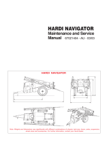
2.1 WORKING SCREEN DISPLAY
Volume
(Flow Rate)
Coverage
Rate
Application Rate
Ground Speed
Volume Left
Alarm Window
Volume Used
Working Screen
12
The above “Working Screen” is what is displayed when the console is first switched ON.
The “Working Screen” is the screen displayed when spraying.
Below is a brief description of what is displayed in each window. The functions listed below
are the default settings, for each window.
Some windows can display more than one function, these are explained on the next page.
Ground Speed- Displays the ‘live’ ground speed from the wheel sensor on the sprayer.
Rate- Displays the ‘live‘ spray rate.
Sub Area- Displays area covered for the active sub area.
The Sub Area window can be selected to display the “Sub Area Number”
and “Total Area”.
Coverage Rate- Displays the working rate of the sprayer in units/hr.
Volume Left-Displays the volume left in the spray tank.
Flow rate-Displays the ‘live’ flow rate in units/minute
Volume Used-Displays the volume used.
Alarm Window-Displays all alarms, actions or warnings in this window.
Sub Area
or Sub Area Number
or Total Area
V 1.0 11/05

E15h SPRAYER- Console Overview
Below will show all the functions that can be displayed in each window. Most of the
functions will have to be enabled in the “Sprayer Setup” before the functions can
be displayed in the windows. The first function listed is the default function
displayed on the screen. See Operation of Sprayer (Section 7.0) on how to access
these functions.
- Displays area covered for the active sub area.
Displays the active Sub Area number.
Displays the total area accumulated by the sprayer since the last reset.
Displays the working rate of the sprayer in units/ha.
Displays the current preset ‘Row Width’ of the sprayer. 4 preset Row
Widths can be set. The current ‘Row Width’ displayed is indicated by the number
(1,2,3 or 4) in the bracket.
Displays the ‘live’ pressure reading from the electronic pressure sensor.
Displays the actual fan speed (in RPM) of the shaft speed the sensor
is fitted to, marked ‘Fan 1 Speed’ on the loom. Is only displayed when 1 or 2 Fan
Monitors are selected in Section .
Displays the amount of product left in the tank.
Displays the status of the Flush function whether OFF or ON; if ON
displays the countdown in seconds of the time left for the flush function to finish
flushing out the boomspray. See Section 3.12.2 to enable Flush function if fitted.
Displays the ‘live’ Flow rate in volume/minute.
Displays the actual speed (in RPM) of any shaft the sensor is fitted
to. Example would be a PTO input shaft. See Section 3.20 to enable, if fitted.
Displays the actual speed (in RPM) of any shaft the sensor is
fitted to. See Section 5.11 to enable, if fitted.
Displays the actual fan speed (in RPM) of the shaft speed the sensor
is fitted to, marked ‘Fan 1 Speed’ on the loom. Is only displayed when 2 Fan
Monitors are selected in Section .
Displays the amount of product applied, since the last reset.
Displays the status of the Auxiliary switch, whether OFF or ON. Enable
this function for example, if Working Lights are fitted to the sprayer loom. See
Section 3.12.2 to enable, if fitted.
Displays the status of the Dump Override, whether ON or OFF.
The Dump Override allows a ‘Chemical Induction’ pump to be fitted to the sprayer.
All Section and Master switches have to be switched OFF to enable ,Dump Override’.
See Section 3.22 to enable.
Displays the current ‘JOB NUM:’ (Job Number) and ‘SET
RATE:’ if the ‘Data Logger’ is ENABLED. See Section 3.14 to enable, if fitted.
13
V 1.0 11/05

Major Topic Heading
V 1.2
E15h SPRAYER-Console Overview
Line 1 Button
Line 3 Button
Line 2 Button
Power Switch
Auxiliary
Rate 2
Rate 1
Line 4 Button
Auto/Manual
Master Switch
Menu Button:
Gateway to set up
Section Switches
2.2 WORKING SCREEN BUTTON FUNCTIONS
INC Button (Up Arrow)
DEC Button (Down Arrow)
Enter
The Eagle console is switched ON and OFF by this switch on the front panel. By
default down is ON.
The MASTER switch turns all sections selected for operation, ON or OFF. By default
down is ON
Light Emitting Diode (LED). The LED’s aligned above (front boom) the section
switches and below (back boom) the section switches indicate the status of the
sections.
The LED’s for the MASTER switch indicates the status of the switch ON or OFF.
The LED’s near the RATE 1 and RATE 2 button indicate which preset spraying RATE
has been selected.
The LED’s near the AUTO/MANUAL button indicates the status whether in AUTO
(LED light is ON) or MANUAL (LED light is OFF).
14
V 1.0 11/05

E15h SPRAYER- Console Overview
1. These switches turn individual Sections ON or OFF. By default down is ON
2. The red LED’s aligned above and below each section switch, indicates the status of
each Section
When the LED light is:
• OFF- The Section switch for that section is switched OFF, temporarily
• Flashing- The Section switch is switched ON but not spraying. Master is OFF
or ground speed is below the LOW SPEED CUT-OFF value.
• On- The Section switch is switched ON, MASTER is ON and nozzles are
spraying at the calibrated spraying rate which is displayed ‘live’ in the
‘Application Rate’ window.
Note: The section LED’s will only turn on for the number of sections set in the
Sprayer Setup Menu. If the sprayer has been setup as a 2 section sprayer, then only
sections LED’s ‘Left Inner’ and Right Inner’ will turn on, when the sections are
switched ON. The led's for sections ‘Left Outer’ and ‘Right Outer’ will not come on,
even if the actual switches are switched ON or OFF.
Sets the application rate to the normal programmed rate when in AUTO.
When LED near RATE 1 button is:
RATE 1 is selected but MASTER switched OFF or spraying in MANUAL.
RATE 1 is selected and spraying to the set rate in AUTOMATIC.
Sets the application rate to a second alternative rate, selectable any time in AUTO.
When LED near RATE 2 button is:
RATE 2 is selected but MASTER switched OFF or spraying in MANUAL.
RATE 2 is selected and spraying to the set rate in AUTOMATIC.
1. Press AUTO/MANUAL button to select between AUTO or MANUAL.
2. When the sprayer is operating in MANUAL the LED near the button will be OFF.
3. When the sprayer is operating in AUTO the LED near the button will be ON.
The Auxiliary Button is used in conjunction with the Navigation Buttons (LINE 2,
LINE 3 and LINE 4) when on the ‘Working Screen’. The operator uses the LINE 2,3 or
4 buttons to select and highlight a window, the window will stay highlighted for 5
seconds, while the window is highlighted and the AUX. button is pressed then
various functions will be displayed in each window. Each time the AUX. button is
pressed the next function is displayed.
What is displayed in each window will depend what functions have been enabled in
the Sprayer Setup Menu. See ‘Working Screen Display’ to view what functions are
displayed in each window.
The AUX. button will only scroll through the various functions while the window is
highlighted. The LINE 2,3 or 4 buttons may have to pressed again to re- highlight
the window.
The last option displayed in the window will stay until changed or the E15h console
is switched OFF, then the windows will display the default options.
15
V 1.0 11/05

E15h SPRAYER- Console Overview
The Navigation Buttons LINE 1, LINE 2, LINE 3 AND LINE 4) allow
the operator to navigate in the MAIN MENU.
LINE 1 selects line 1 of the display; LINE 2 selects line 2 of the display and so on
for LINE 3 and LINE 4. If the operator selects LINE 3 then the window on LINE 3
will be highlighted. If the operator presses LINE 3 again then the column 2 will
be highlighted; if permitted. When LINE 3 is pressed again, column 3 will be
highlighted. If LINE 3 is pressed a third time, the first column will be highlighted
again.
When on the Working screen the Navigation Buttons (LINE
2, LINE 3 and LINE 4) can be used in conjuction with AUX. button to scroll
through the various options within each window so the ‘Working Screen’ can be
tailored made to suit different operators needs. See AUX. button on previous
page.
The Increase and Decrease(INC/DEC) buttons when on the
‘Working Screen’ allow the operator to increase or decrease the spraying rate,
while spraying in Manual or Auto.
The INC/DEC buttons when in the MAIN MENU allow the operator to increase
and decrease factors (when a asterisk (*) appears next to the value), in the MAIN
MENU. When using the INC/DEC buttons to change a value, the operator may
press the INC/DEC button repeatedly to change the value OR the operator may
press and hold the INC or DEC button and the value will change while the button
is depressed; the longer the button is depressed the faster the values will change.
When the ENTER button is pressed, the value within the highlighted
window, has an asterisk (*) appear next to the value. The value can be increased
or decreased using the INC/DEC buttons. Press the ENTER button again to lock-in
and save the value.
When the MASTER switch is in the OFF position, the MENU button,
when pressed, is the gateway into the MAIN MENU’s for the Console.
MENU also returns to the Working Screen from any menu, (the button may have
to be pressed several times to return to the WORKING SCREEN).
Press MENU once to return to the previous menu.
When the MASTER switch is ON and the MENU button is pressed, the Fan Speed
Monitoring screen is displayed when a FAN MONITOR ECU is connected to the
E15h console.
V 1.0 11/05
16

E15h SPRAYER- Console Overview
• Press MENU. To enter the MAIN MENU screen
To enter the MENU screens ensure the MASTER switch is in the OFF position.
Note: All procedures assume the operator is starting from the “Working Screen”.
• To advance to the SETUP MENU see Section 2.5
• To advance to the OPERATING HISTORY see Section 6.0
2.3 MAIN MENU
Operations Menu Screen
17
V 1.0 11/05

E15h SPRAYER- Console Overview
• Press MENU.
To enter OPERATIONS MENU screen
• Press ENTER.
To enter SETUP MENU screen
• To advance to the SPRAYER SETUP MENU see Section 3.0
• To advance to the ALARMS SETUP MENU see Section 4.0
• To advance to the CONTROLLER SETUP MENU see Section 5.0
2.4 SETUP MENU
Setup Menu Screen
V 1.0 11/05
18

E15h SPRAYER- Sprayer Setup Operation
3.0 SPRAYER SETUP MENU
Sprayer Setup Screen
• Press MENU
• Press ENTER to select SETUP
• Press ENTER to select SPRAYER SETUP
19
V 1.0 11/05

E15h SPRAYER- Sprayer Setup Operation
3.1 SET THE PRESET RATE 1
Note: This sets the “Main Target” Rate for the sprayer, and activated by the
RATE 1 button on the console.
• Press MENU
• Press ENTER to select SETUP
• Press ENTER to select SPRAYER SETUP.
The focus window will be on
TARGET RATE
• Press ‘RATE 1’ button.
The LED next to the ‘RATE 1’ button will light up.
The current TARGET RATE will be displayed in the window.
• Press ENTER to edit TARGET RATE.
An asterisk (*) should appear after
“TARGET RATE”
• Use Inc/Dec (Up and down arrows) to set the TARGET RATE 1
• Press ENTER to accept the changes
3.2
SET THE PRESET RATE 2
Note: This sets the “2nd Target” Rate for the sprayer, and is activated by the
RATE 2 button on the console.
• Press MENU
• Press ENTER to select SETUP
• Press ENTER to select SPRAYER SETUP.
The focus window will be on
TARGET RATE
• Press RATE 2 button.
The LED next to the RATE 2 button will light up.
The current TARGET RATE will de displayed in the window.
• Press ENTER to edit TARGET RATE.
An asterisk( *) should appear after
“TARGET RATE”
• Use INC/DEC buttons to set the TARGET RATE
• Press ENTER to accept the changes
3.3.
MINIMUM FLOW HOLD VALUE
NOTE: This feature alarms the operator when the flow of liquid going through
the flowmeter drops below the value set in the MINIMUM FLOW VALUE.To
switch the MINIMUM FLOW HOLD alarm ON or OFF, go to Section 4.1.1
If this feature is not required, then set the MINIMUM FLOW to ‘0’
• Press MENU
• Press ENTER to select SETUP
• Press ENTER to select SPRAYER SETUP
• Press LINE 1 button to move the focus to MINIMUM FLOW (1)
The current value
is displayed in the window.
• Press ENTER.
An asterisk (*) will be displayed after MINIMUM
• Press INC/DEC buttons, to set the MINIMUM FLOW value.
20
V 1.0 11/05
/