Page is loading ...

P.O. Box 309, Menomonee Falls, WI USA 53052-0309
800 BRADLEY (800 272 3539) +1 262 251 6000
bradleycorp.com
Installation
HDWP-INSTR-013 Rev. K; ECN 12-14-012
© 2014 Bradley
Page 1 of 21 10/1/2014
Bradmar
™
Restroom Partitions
Overhead Braced - Series 400
(includes No-Site style)
Table of Contents
Pre-Installation Information ....................2
Layout Dimensions for Brackets ................3
Mounting Brackets to Wall .....................4
Leveling Bolts to Pilaster ......................5
Brackets to Pilasters .......................5–6
Pilaster Shoes ..............................6
Mounting Panels and Pilasters ...............7–8
Headrail ...................................9
Hinges ................................10–14
Latch and Strike/Keeper ..................15–18
Stiffener Bracket............................19
Urinal Screens ..........................20–21
IMPORTANT
Read this installation manual completely to ensure proper installation, then file it with the owner
or maintenance department. Compliance and conformity to local codes and ordinances is the
responsibility of the installer.
Separate parts from packaging and make sure all parts are accounted for before discarding packag-
ing material. If any parts are missing, do not begin installation until you obtain the missing parts.
Leave the protective masking on until installation is complete. To prevent warping, always lay the
material flat. Do not lean the material against the wall or stack unevenly. Allow 24 hours for material
to adjust to site environment.
Use caution when drilling. Accuracy is important!
Partitions should be installed in a climate-controlled environment and shielded from direct sunlight.
Product warranties and parts information may also be found under ”Products” on our web site at
bradleycorp.com.
Installation
THIS
SIDE
UP
Packing List
•
•
•
•
For Standard Height
Doors and Panels Only
*HDWP-INSTR-013*

2
Bradmar
™
Restroom Partitions, Floor-Mounted with Overhead Brace — Series 400 Installation
10/1/2014 Bradley • HDWP-INSTR-013 Rev. K; ECN 12-14-012
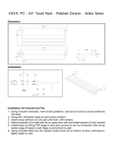
Supplies Required:
Hardware Provided
#14-2" Button HD
Sheet Metal Screw
TORX-T27 Drive
FAST-P002
#14-¾" Button HD
Sheet Metal Screw
TORX-T27 Drive
FAST-P001
#14-16 Plastic
Anchor
FAST-T373
⁵⁄₁₆" x 1½"
HEX HD Lag
FAST-S008
#8-1" Flat HD
Sheet Metal Screw
Phillips Drive
FAST-P006
#10-24 x 2" Flat
HD Machine Screw
TORX-T25 Drive
FAST-S0027
Washer Flat
⁹⁄₃₂" x ⁵⁄₈"
P10-449
Example of Submittal Drawing
• Chalklineandpencil
• FlatbladeandPhillipsheadscrewdrivers
• Jigsaworhacksaw
• Circularsaw
• Twospringclamps
• ³⁄₃₂", ⁷⁄₆₄", ¹⁄₈", ⁵⁄₃₂", ¹³⁄₆₄", ⁷⁄₃₂"and¼"drillbits
• Powerdrillorscrewgunwithdrillbitextension
• Tapemeasureand4'level
• ⁵⁄₁₆"ceramictileandmasonrydrillbit
• Hammerdrill
• Spacer,14"(356mm)highandstrongenoughto
support the panel
#10-24 x ¾" Button HD
Barrel Nut
TORX-T27 Drive
FAST-P003
#10 x ¾" Flat HD
Sheet Metal Screw
TORX-T25 Drive
FAST-S0006
#6 x ¾"
Phillips Flat-Head
Sheet Metal Screw
FAST-P011
#10-¾" Button HD
Sheet Metal Screw
TORX-T25 Drive
FAST-P005
#10-24 x ¾" Button HD
Shoulder Screw
TORX-T27 Drive
FAST-P004
60½"(1537mm)
WalltoCenter
Line
61¼"
(1556mm)
to
Face
36"(914mm)
CentertoCenter
1"(25mm)
Gap
½"(13mm)
Gap
1"(25mm)
Gap
7"
(178mm)
26"
(660mm)
24"
(610mm)
19.5
4
4.5
5.5
1.5
58 ¾"
(1492mm)
58 ¾"
(1492mm)
36"
(914mm)
4"
(102mm)
#14-⁵⁄₈" Button HD
Sheet Metal Screw
TORX-T27 Drive
FAST-S0016
#10-⁵⁄₈" Button HD
Sheet Metal Screw
Torx-T27 Drive
FAST-S0019

3
Installation Bradmar
™
Restroom Partitions, Floor-Mounted with Overhead Brace — Series 400
Bradley • HDWP-INSTR-013 Rev. K; ECN 12-14-012 10/1/2014
*
*
*
*
*
*
*
*
*
Pilaster
PlumbLine
When installing the partition components, consult
the applicable Mills Partition submittal drawing
for compartment layout dimensions.
1a
Layout Dimensions - Stirrup Brackets (Optional)
Pilaster Shoe Centerline: Measure from
thebackwallforwardtothefaceofthe
compartment,subtract½"(13mm)and
markthislocationonthefloor(“A”).Mark
the same measurement on the opposite
endofyourlayout(“A1”)anddrawa
straightlineconnectingbothmarks.
FOR FREESTANDING (FS) PARTITION:
Refertosubmittaldrawingsanddetermine
the approximate location of the outside
panels.Establishdimensions“A”and“A1”
asexplainedabove.
A
Panel centerline: Measure the stall width across the
backwallandplaceamarkatthebaseoftherearwall
(“B”).Repeatthisstepforeachpanel,startingeach
measurementfromthelastpanelcenterline(“B1”).
B
Stirrup brackets:Drawaplumblineonallwalls
from each pilaster and panel centerline. From the
highestpointintheroom,measure20"(508mm),
41½"(1054mm)and63"(1600mm)fromthefloor
andplaceamarkonthepilaster/panelplumbline
("C").Thesemarksrepresenttheholecenterline
ofthestirrupbrackets.Usealeveltotransferthat
marktoallotherplumblines.
C
Panel
plumbline
63"
(1600mm)
41½"
(1054mm)
"A"
"B"
"B1"
"A1"
"C"
"C"
"C"
"C"
"C"
"C"
"C"
"C"
"C"
20"
(508mm)
C
L
C
L
C
L
C
L
C
L
C
L
C
L
C
L
C
L
C
L
Pilaster
PlumbLine
When installing the partition components,
consult the applicable Mills Partition submittal
drawing for compartment layout dimensions.
1
Layout Dimensions - Continuous Brackets (Standard)
Pilaster Shoe Centerline: Measure from
thebackwallforwardtothefaceofthe
compartment,subtract½"(13mm)and
markthislocationonthefloor(“A”).Mark
the same measurement on the opposite
endofyourlayout(“A1”)anddrawa
straightlineconnectingbothmarks.
FOR FREESTANDING (FS) PARTITION:
Refer to submittal drawings and
determine the approximate location of the
outside panels. Establish dimensions “A”
and “A1” as explained above.
A
Panel centerline: Measure the stall width across the
backwallandplaceamarkatthebaseoftherearwall
(“B”).Repeatthisstepforeachpanel,startingeach
measurementfromthelastpanelcenterline(“B1”).
B
Continuous brackets: Drawaplumblineonallwallsfromeach
pilaster and panel centerline. From the highest point in the room,
measure14½"(369mm)fromthefloorandplaceamarkonthe
pilaster/panelplumbline.Usealeveltotransferthatmarktoall
otherplumblines(“C”).
C
Panel
plumb
line
"C"
"C"
"C"
"A"
"B"
"B1"
"A1"
*
*
*
14½"(369mm)To
bottomofbracket
(highestpointin
floor)

4
Bradmar
™
Restroom Partitions, Floor-Mounted with Overhead Brace — Series 400 Installation
10/1/2014 Bradley • HDWP-INSTR-013 Rev. K; ECN 12-14-012
2a
Stirrup Brackets to Wall (Optional)
establishedlevelline
pilaster/panelplumbline
floor
C
L
Place the center of the stirrup
bracketateachestablished
levelline.Centerthebracket
opening on the pilaster/panel
plumbline.
A
Insert the plastic anchors
in all holes and secure the
bracketstothewallwiththe
#14 x 2" screws provided.
C
On end panel and pilaster applications, position the bracket
with the ear facing toward the inside of the stall.
Usingthebracketasa
template, mark the hole
locations on the wall.
Removethebracketand
drill a Ø ⁵⁄₁₆"hole(min.
2"[51mm]deep)ateach
hole location.
B
One-Eared
Bracket
Two-Eared
Bracket
2
Continuous Brackets to Wall (Standard)
establishedlevelline
pilaster/panel
plumbline
floor
C
L
Placethebottomofthe
continuousbracketatthe
establishedlevelline.Center
thebracketopeningonthe
pilaster/panelplumbline.
A
Insert the plastic
anchors in all holes
and secure the
bracketstothewall
with the #14 x 2"
screws provided.
C
On end panel and pilaster applications, position the bracket
with the ear facing toward the inside of the stall.
Usingthebracket
as a template, mark
the hole locations on
the wall. Remove the
bracketanddrilla
Ø ⁵⁄₁₆"hole(min.2"
[51mm]deep)ateach
hole location.
B
Brackets are used as templates but, since the hole patterns may
be different, the brackets may not be interchanged.
One-Eared
Bracket
Two-Eared
Bracket

5
Installation Bradmar
™
Restroom Partitions, Floor-Mounted with Overhead Brace — Series 400
Bradley • HDWP-INSTR-013 Rev. K; ECN 12-14-012 10/1/2014
3
Leveling bolts to Pilaster
Notch indicates
bottomofintegral
hinge pilaster
Notch indicates
bottomofintegral
hinge pilaster
Use leveling screw to adjust
height of pilaster
Use leveling screws to
adjust height of pilaster
Drill a Ø ¹³⁄₆₄" pilot hole,
1½"(38mm)deep.Hole
shouldbeapproximately
centered for pilasters 3"–16"
(76mm–406mm)wide.
A
Drill a Ø ¹³⁄₆₄"pilothole,1½"(38mm)
deep.Holeshouldbe2"(51mm)
off each end for the pilasters
18"–24"(457mm–610mm)wide.
A
4
Continuous Brackets to Pilaster (Standard)
Refer to the submittal drawing to locate the split
dimension and layout location of each marked pilaster.
Locate Brackets: Measure down from the top of the
pilaster and place a mark on the pilaster split centerline
atdimensionsat13½"(343mm)and67½"(1715mm).
Pilaster shown is for reference only. Actual pilaster
varies depending on application.
A
Securethebrackets.
For "H" Bracket:Usethebracketasa
template, drill a Ø ¼" holes through the
pilaster/panelandsecurethebracketto
the pilaster and panel with #10-24 x ¾"
barrelnutsand#10-24x¾"shoulder
screws provided.
For continuous bracket:Securethebracket
to the pilasters using the #14 x ¾" screws
provided.
C
Split
Split
13½"
(343mm)
67½"
(1715mm)
Placethecontinuousbracketbetweeneachestablished
levelline.Centerthebracketopeningonthepilaster
splitcenterline.Usingthebracketasatemplate,mark
theholelocationsonthepilaster.Removethebracket
and drill a Ø ⁷⁄₃₂ x¾"(19mm)deeppilotholeateach
location.
B
Brackets are used as templates but, since the hole patterns may
be different, the brackets may not be interchanged.
C
L

6
Bradmar
™
Restroom Partitions, Floor-Mounted with Overhead Brace — Series 400 Installation
10/1/2014 Bradley • HDWP-INSTR-013 Rev. K; ECN 12-14-012
4a
Stirrup Brackets to Pilaster (Optional)
Refer to the submittal drawing to locate the split
dimension and layout location of each marked pilaster.
Locate Brackets: Measure down from the top of the pilaster
and place a mark on the pilaster split centerline at dimension
"A","B"and"C"fortherespectivebracket(seetableatleft).
Pilaster shown is for reference only.
Actual pilaster varies depending on application.
A
Placethecenterofeachstirrupbracketateach
establishedlevelline.Centerthebracketopening
onthepanelplumbline.Usingthebracketas
a template, mark the hole locations on the
pilaster.RemovethebracketanddrillaØ⁷⁄₃₂" x
¾"(19mm)deeppilotholeateachlocation.
B
Split
Split
"A"
"B"
"C"
"U"
Bracket
"H"
Bracket
Dim. "A"
19"
(483mm)
13½"
(343mm)
Dim. "B"
40½"
(1029mm)
67½"
(1715mm)
Dim."C"
62"
(1575mm)
—
Securethestirrupbracketsto
the pilasters using the #14 x ¾"
screws provided.
Refer to step 4 for location and
attachmentof"H"bracket.
C
5
Pilaster Shoes
Thisviewisanexampleonly.Refertoyoursubmittaldrawingsforactualsizes.Layoutthe
pilasteranddoorwidthsonthepilastercenterline,leavingtheappropriategapbetween
the wall and pilaster. Place the corresponding shoe on the pilaster centerline, center the
shoebetweenthepilastermarks.Usingtheshoesasatemplate,marktheholelocations.
A
Insert plastic anchors
into the holes and fasten
the shoe to the anchors
using hardware provided.
C
Drill Ø ⁵⁄₁₆"holes(min2"
[51mm]deep)inthefloor
and make sure the holes
arefreeofdirtanddebris.
B
Install the shoes starting with the one closest to the wall
36"(914mm)
Door Opening
PilasterCenterline
24"(610mm)
4"
(102mm)
7"
(178mm)
1"(25mm)Gap
26"(660mm)
Door Opening
⁹⁄₃₂" x ⁵⁄₈" Flat Washer
#14 x 2" Screw
Stainless Steel Shoe
Plastic
Anchor

7
Installation Bradmar
™
Restroom Partitions, Floor-Mounted with Overhead Brace — Series 400
Bradley • HDWP-INSTR-013 Rev. K; ECN 12-14-012 10/1/2014
6
Panels and Pilasters with Continuous Brackets (Standard)
Pilasters located at walls should be mounted first. Start at one end and install a panel, then a pilaster.
Continue alternating until installation is complete. When installing in an alcove or in-corner alcove, use an "H"
bracket to secure the pilaster to the panel.
When installing pilasters at walls, the gaps range
from ½" to 1¼" (13mm to 32mm). Refer to your
submittal drawing for your gap sizes.
Check to make sure the pilasters are plumb and level to each other. The pilaster height can be adjusted with
the leveling screw that was placed at the bottom of the pilaster (see page 5 for attaching leveling bolt).
Refer to your submittal drawing and leave the appropriate
gaps. Standard gap is 1" (25mm) between the panel and
wall and ½" (13mm) between the panel and pilaster.
Usingthebracketasatemplate,drillؼ"
holes through the pilaster at each pilaster
brackethole.Securethepilastertothebracket
with#10-24x¾"barrelnutsand#10-24x¾"
shoulder screws provided.
Using the hole in the shoe as a template, drill a
Ø ¼" hole through the pilaster and secure the
shoetothepilasterwith#10-24x¾"barrelnuts
and #10-24 x ¾" shoulder screws provided.
Using the hole in the shoe as a template, drill a Ø ¼"
hole through the pilaster and secure the shoe to the
pilasterwith#10-24x¾"barrelnutsand#10-24x¾"
shoulder screws provided.
Set the pilaster into the shoe while at the
sametimeplacingintothewallbracket.
A
Place a panel on the spacer and insert the panel into
thewallbracket.
Set the pilaster into the shoe while at the same time
placingthebracketaroundthepanel.
A
B
Usingthebracketsasatemplate,drillؼ"holesthrough
thepanelateachpanelbrackethole.Securethepanelto
thebracketswith#10-24x¾"barrelnutsand#10-24x¾"
shoulder screws provided.
B
C
C
Spacer14"(356mm)
Aluminum heatsink
onbottomofpanel.
Pilasters at Wall Pilasters with Panels

8
Bradmar
™
Restroom Partitions, Floor-Mounted with Overhead Brace — Series 400 Installation
10/1/2014 Bradley • HDWP-INSTR-013 Rev. K; ECN 12-14-012
6a
Panels and Pilasters with Stirrup Brackets (Optional)
Pilasters located at walls should be mounted first. Start at one end and install a panel, then a pilaster.
Continue alternating until installation is complete. When installing in an alcove or in-corner alcove, use an "H"
bracket to secure the pilaster to the panel.
When installing pilasters at walls, the gaps range
from ½" to 1¼" (13mm to 32mm). Refer to your
submittal drawing for your gap sizes.
Check to make sure the pilasters are plumb and level to each other. The pilaster height can be adjusted with
the leveling screw that was placed at the bottom of the pilaster (see page 5 for attaching leveling bolt).
Refer to your submittal drawing and leave the appropriate
gaps. Standard gap is 1" (25mm) between the panel and
wall and ½" (13mm) between the panel and pilaster.
Usingthebracketsasatemplate,drillؼ"
holes through the pilaster at each pilaster
brackethole.Securethepilastertothebracket
with#10-24x¾"barrelnutsand#10-24x¾"
shoulder screws provided.
Using the hole in the shoe as a template, drill a
Ø ¼" hole through the pilaster and secure the
shoetothepilasterwith#10-24x¾"barrelnuts
and #10-24 x ¾" shoulder screws provided.
Using the hole in the shoe as a template, drill a Ø ¼"
hole through the pilaster and secure the shoe to the
pilasterwith#10-24x¾"barrelnutsand#10-24x¾"
shoulder screws provided.
Set the pilaster into the shoe while at the
sametimeplacingintothewallbrackets.
A
Place a panel on the spacer and insert the panel into
thewallbrackets.
Set the pilaster into the shoe while at the same time
placingthebracketsaroundthepanel.
A
B
Usingthebracketsasatemplate,drillؼ"holesthrough
thepanelateachpanelbrackethole.Securethepanelto
thebracketswith#10-24x¾"barrelnutsand#10-24x¾"
shoulder screws provided.
B
C
C
Spacer14"(356mm)
Aluminum heatsink
onbottomofpanel.
Pilasters at Wall Pilasters with Panels

9
Installation Bradmar
™
Restroom Partitions, Floor-Mounted with Overhead Brace — Series 400
Bradley • HDWP-INSTR-013 Rev. K; ECN 12-14-012 10/1/2014
Foropenendapplications,cuttheheadrailtotheappropriatelength(if
required).Attachthebrackettothewallatthecorrectheight(seestepB).
Attachanotherbrackettoapilasterwith#10x¾"screwsatthecorrect
height(seeviewbelow).Theheadrailshouldbelevelwithanyadjacent
headrailandshouldbelocateddirectlyoverthepanel.Positioneach
headrailontothebracketsandsecurewithrequiredfasteners(seeStepC).
Usingarubbermallet,installtheheadrailendcap.
E
7
Headrail
Make sure the pilasters are plumb and that the pilaster has been secured to the shoe. Leave the appropriate door opening
between the pilasters as shown on your submittal drawing.
Place headrail over the top of the pilasters
andslideittightintothemountingbracket.
Usethemountingbracketasatemplateand
drill a Ø ⁷⁄₃₂" hole through the headrail. Secure
theheadrailtothemountingbracketwiththe
#10 x ⁵⁄₈" screws provided.
C
Makesurethepilasterisplumbandthatthespacingbetweenthe
pilastersforthedoorsisthecorrectdimension.Onthebackofeach
pilaster(startingwiththefirstpilaster),drillaØ⁷⁄₃₂" hole through one
face of the headrail only.
Using this hole as a template, drill a Ø ¹⁄₈" pilot hole into the pilaster,
¾"(19mm)deep.Securetheheadrailtothebackofeachpilaster
with the #10 x ¾" screws provided.
D
Completed Headrail Assembly
The illustrations on this page show mounting hardware and fasteners for a generic application. Refer to your submittals
to determine your actual headrail configurations.
Some headrail sections may need to be cut to an appropriate size. Refer to your submittals for general headrail placement.
Place headrail over the top of each pilaster
located at the wall and slide it tight against
the side wall. Mark the outline of the headrail
on the wall and remove the headrail.
A
Wall
Placetheheadrailbracketontheoutlinemarkedonthewalland
markthelocationsofthemountingholes.Removebracketand
drill(2)Ø⁵⁄₁₆"holesataminimumof2"(51mm)deep.Priorto
securingtothewall,enlargethe(2)backmountingholesofthe
brackettoؼ".Securethebrackettothewallwiththe#14x2"
screws and plastic anchors provided.
B
Headrail configurations that come to an intersection should meet over pilaster (see completed headrail assembly view below).

10
Bradmar
™
Restroom Partitions, Floor-Mounted with Overhead Brace — Series 400 Installation
10/1/2014 Bradley • HDWP-INSTR-013 Rev. K; ECN 12-14-012
Aluminum Heatsink on
bottomofdoor
8
Integral Hinges (Standard)
Top and bottom pintles are pre-
lubricated for your convenience.
Do not remove lubricant.
Pilaster
Spring
3" Top
Pin
Door
Set
Screw
¾"
3"
3³⁄₈" Top
Pintle
3¼" Bottom
Pintle Assy.
¾"
(19mm)
Insert top pintle into the
bottomofthedoor.Besure
thepintlebottomsout(usethe
bottompintletopushthetop
pintleintothedoor).
A
Using a Ø ¹⁄₈"(3mm)drillbit,drillapilot
hole for the set screw into the center
ofthedooredge(approximately¾"
(19mm)downfromthetopofthedoor).
Besuretodrillatleast1½"(38mm)to
penetrate the top pin in the door.
Screw the set screw in flush with the
door'ssurface,thencheckforproper
door operation.
If the door is installed and pinned
correctly, the door will "raise" slightly
on the pintles as the door is opened.
F
Insertthebottompintleinto
thepilasterbottom.Position
thedoorontothebottom
pintleassemblyonthe
pilaster and swivel the door to
engage the pintles.
Insert the spring and the top
pin into the pilaster top.
Move the top of the door into
position while pushing the top
pin into the pilaster. Release
the top pin and force the pin
tobottomoutinthedoor.
C
D
Using a Ø ¹⁄₈"drillbit,drilla
pilot hole for the set screw into
the center of the door edge
(approximately¾"(19mm)up
fromthebottomofthedoor).
Be sure to drill at least 1½"
(38mm)topenetratethetop
pintle in the door. Screw the
set screw in flush with the
door'ssurface.
B
With the door "at rest"
position, drill a Ø ¹⁄₈" hole for
the set screw in the center
of the pilaster edge, down
3"(76mm)fromthecutout.
Be sure to drill at least 1½"
(38mm)topenetratethe
bottompintleassemblyinthe
pilaster.
Screw the set screw in flush
withthepilaster'ssurface.
Position the door at the desired
"at rest" position. Push down
on the door to make sure the
topandbottompintlesare
engaged properly.
E
Repeat steps A-F for all doors
G
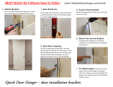
Before installing the hinges, make sure the door openings are the appropriate size, all pilasters are
plumb and secured to the shoe. Determine the door swing by facing the compartment from the outside.
Refer to your submittal drawings to determine each specific door swing for your application.
Right-hand
inswing
(RHI)
Left-hand
inswing
(LHI)
Right-hand
outswing
(RHO)
Left-hand
outswing
(LHO)

11
Installation Bradmar
™
Restroom Partitions, Floor-Mounted with Overhead Brace — Series 400
Bradley • HDWP-INSTR-013 Rev. K; ECN 12-14-012 10/1/2014
8a
Integral Hinges - No-Site (Standard)
Installing the heat sink after the doors are installed is difficult due to the limited space between the
bottom of the door and the floor. The heat sink should be installed prior to completing step "C".
Aluminum heatsink
onbottomofdoor
Pilaster
Spring
3" Top Pin
Lip
Lip
3"
(76mm)
3³⁄₈" Top Pintle
3¼" Bottom
PintleAssembly
Notch Feature
(foradjacent
doorstrike)
¾"
(19mm)
1¾"
(44mm)
½"
(13mm)
¾"
Drill first hole as shown. Attach and align
heatsinkwithsinglescrew(#6x¾"flat
headscrew).Useremainingheatsink
holes as a drilling template and fasten with
remaining screws
SameprocedureaslettersA–Fforstep8.Seebelowforinstructionsandnoteson
installingthealuminumheatsinkonbottomofdoorpriortostartinginstallation.
A
The "lip" will be on the outside of the stall for outswing doors and on the inside for inswing doors.
The heat sink should always be on the bottom.
Ø ⁷⁄₆₄ x ¾"
Deep
(allPilot
Holes)

12
Bradmar
™
Restroom Partitions, Floor-Mounted with Overhead Brace — Series 400 Installation
10/1/2014 Bradley • HDWP-INSTR-013 Rev. K; ECN 12-14-012
8b
Continuous Spring Loaded Piano Hinge (Optional)
Spacer14"(356mm)
abovefinishedfloor
Usea14"(356mm)spacer
to help support the weight of
the door.
(FOR ALUMINUM HINGE:
removesnap-onfaceplate)
Place the door on the spacer
and set the gap at the hinge
and latch side. Standard gap
is
³⁄₁₆"(5mm).
A
Centerthehingeintheopening
opposite the latch and top to
bottomondoor(approximately½"
[13mm] down from the top of the
door)
B
RepeatproceduresA-CforStainlessSteelHinges
and procedures A-D for Aluminum Hinges.
E
Using the hinge as a template, drill a Ø ¼"
holethroughthedooratthetopandbottom
hole. Secure the hinge to the door with the
#10-24 x ¾" shoulder screws and #10-24 x ¾"
barrelnutsprovided.
Ensure that the gap on the latch side is
consistentandrepeatprocedureConthe
pilaster side.
Then drill a Ø ¼" holes through the remaining
hinge holes on the door and pilaster. Secure
with the fasteners provided.
C
ALUMINUM HINGE ONLY, FOR STAINLESS STEEL
SKIP THIS STEP: Hold the snap-on faceplate squarely on
theleaf.Tapthefaceplatefirmlyusingasoftwoodblockto
protectthefinishfromhammerblows.Startatthetopand
work downward until the entire length of the faceplate is
firmly engage. Secure the faceplate with a #8 x 1" flat head
Phillips drive screw.
To adjust spring tension, use a torx screwdriver and turn
the torx head clockwise approximately one complete
revolution.Inserta1½"(38mm)longnailintothehole
through the hinge pin. The hinge pin has a hole in two
directionsallowingadjustmentstobemadeatevery¼turn.
Checktheswingofthedoor.Ifthedoordoesnotclosefast
enough, remove the temporary nail and turn the torx head
¼ turn.
When desired tension is reached, hold the torx head in
place, remove the nail and insert the roll pin. Tap the roll
pinintoplacewithanailsetuntil1/8"(3mm)remainsout
from the hinge.
D
Closed
Door View
Before installing the hinges, make sure the door openings are the appropriate size, all pilasters are
plumb, secured to the shoe and that the headrail is installed. Determine the door swing by facing the
compartment from the outside. Refer to your submittal drawings to determine each specific door swing
for your application.
Right-hand
inswing
(RHI)
Left-hand
inswing
(LHI)
Right-hand
outswing
(RHO)
Left-hand
outswing
(LHO)
Continuous Piano Hinge
Part # Prefix HDWP-S0209 Part # Prefix HDWP-S0208
Thepartnumberslistedareprefixesonlyand
are used to identify the appropriate door kit
basedonyourdoorswingasdeterminedabove.
Inswinging doors should have hinges mounted
on the inside of the stall while outswinging doors
should have hinges mounted on the outside of
the stall.
(lefthandin,righthandout,
knucklesfacingfront)
(righthandin,lefthandout,
knucklesfacingfront)
Door
side
Pilaster
side
Pilaster
side
Door
side

13
Installation Bradmar
™
Restroom Partitions, Floor-Mounted with Overhead Brace — Series 400
Bradley • HDWP-INSTR-013 Rev. K; ECN 12-14-012 10/1/2014
Top and
Bottom Insert
Female(2)
Bottom Insert
Malew/Cutoff
Cam&Spacer
(1)
Top Insert w/
CamMale(1)
Aluminium
Hinge Blank
(4)
Left In and Right Out Assembly
Top Hinge Set
Bottom Hinge Set
Insert
Correct
Incorrect
Hinge
Blank
Aluminum Hinge Blank
Reference
Mark
Reference
Mark
Top and
Bottom Insert
Female
Bottom Insert
Malew/Cutoff
Cam&Spacer
Top Insert w/
CamMale
Top Hinge Set
Bottom Hinge Set
Cam
Cutoff
Cam
Right In and Left Out Assembly
8c
Aluminum Wraparound Hinge (Optional)
Before installing the hinges, make sure the door openings are the appropriate size, all pilasters are
plumb, secured to the shoe and that the headrail is installed. Determine the door swing by facing the
compartment from the outside. Refer to your submittal drawings to determine each specific door swing
for your application.
Hinge blanks and inserts have reference marks
that are used in setting the hinge position. The
hinge contains the cam mechanism and the bottom
hinge has the cutoff cam with spacer.
Right-hand
inswing
(RHI)
Left-hand
inswing
(LHI)
Right-hand
outswing
(RHO)
Left-hand
outswing
(LHO)
Separate the hinge components and ensure all parts
are included as shown
A
Assembleinsertsintothehingeblanksmakingsurethe
insertcollarfitstightlyagainsteachofthehingeblanks.
D
Align the reference marks of the inserts and hinge
blanksasshown.
C
Findthehingeassemblythatcoincideswiththedoor
swing. Arrange the hinge sets as shown.
B
Pilaster Side
Pilaster Side
Pilaster Side
Pilaster Side
Door Side
Door Side
Door Side
Door Side

14
Bradmar
™
Restroom Partitions, Floor-Mounted with Overhead Brace — Series 400 Installation
10/1/2014 Bradley • HDWP-INSTR-013 Rev. K; ECN 12-14-012
Closed
Upper Blank
Top Hinge Set
#8 x 1"
Stainless
Steel Phillips
head screw
#8 x 1" Stainless
Steel Phillips head
screw
Cardboard
Spacer
#10-24 x¾"
Shoulder
Screw
Aluminum
Heat Sink
#10-24 x ¾"
Barrel Nut
Lower Blank
Bottom Hinge Set
#10-24 x ¾"
Shoulder
Screw
#10-24 x ¾"
Barrel Nut
Lower
Blank Top
Hinge Set
Upper Blank
Bottom
Hinge Set
2"(51mm)
2"
AlignCammedInsert
Reference Mark
AlignCammedInsert
Reference Mark
AlignCammedInsert
Reference Mark
30° Open
PositiveClosed
8c
Aluminum Wraparound Hinge (Optional)
Set the "at rest" position for the door
byadjustingthepositionofthetop
maleinsertinthehingeblank.
E
Ensure
Hinge set
is fully
engaged
Ensure hinge
set is fully
engaged to
cardboard
spacer
Aluminum
Heat Sink
Tape
Tape
Assemblethehingesetsonthe
door. Use tape to hold the hinge
sets together
H
Placetheupperblankofthetophingesetonthedoor2"(51mm)from
the top. Using the hinge as a template, drill a Ø ³⁄₃₂"x1"(25mm)deep
pilot hole into the edge of the door. Secure the hinge to the door with
a #8 x 1" stainless steel Phillips head screw. Then repeat the same
procedureforlowerblankofthebottomhingeset.
Usinga14"(356mm)spacer,
support the door in the opening.
Removetapeandcardboard
spacer from the hinge set
As the door is moved
intoplace,slipbothhinge
blanksonthepilaster.
AttachLowerblankof
the top hinge set to the
pilaster. Using the hinge as
a template, drill Ø ¼" holes
through the hinge set and
door. Secure with
#10-24 x ¾" shoulder
screws and #10-24 x ¾"
barrelnuts.
Then repeat the same
procedureforupperblank
ofthebottomhingeset.
F
I
L
J
K
Using the hinge as a template, drill
ؼ"holesthroughbothhinge
sets and the door. Secure with
#10-24 x ¾" shoulder screws and
#10-24x¾"barrelnuts.Place
thecardboardspaceronthemale
insert of the lower hinge set.
G
Make sure that the upper and
lower portions of each hinge
set are fully engaged.

15
Installation Bradmar
™
Restroom Partitions, Floor-Mounted with Overhead Brace — Series 400
Bradley • HDWP-INSTR-013 Rev. K; ECN 12-14-012 10/1/2014
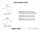
9
Latch and Strike/Keeper for Inswing Doors
Local codes vary from state to state. Check your local
codes before installing the coat hook and door pulls.
D
C
Line up the center hole of the strike/keeper with the mark on
the pilaster. Using the strike/keeper as a template, drill Ø ¼"
holes through the pilaster. It is not necessary to remove the
strike/keeperbeforedrilling.Securethestrike/keepertothe
pilaster using hardware provided.
E
For32"-26"(813mm–914mm)ADAdoors,measure5½"
(140mm)fromthelatchedsideofthedoorand25¾"down
from the top of the door. Drill Ø ¼" hole through the face of
thedoor.Drillanidenticalhole,3½"(89mm)belowthehole
just drilled. Install one door pull to each side of the door with
the hardware provided.
Using the latch mounting holes as a template, drill a Ø ⁷⁄₃₂"
pilotholeintothedoor,¾"(19mm)deep.Securethelatchto
the door using hardware provided.
A
B
F
G
With the door in the closed position, set
the latch on the inside of the door so that
theslidebariscenteredintheslotonthe
strike/keeper. The leading edge of the
latchshouldbepositionedapproximately
³⁄₈"(10mm)fromthedooredge.
Install the coat hook in the upper corner on
the inside of the door on the latched side
atalocation3"(76mm)downfromthetop
and3"(76mm)infromtheside.Usingthe
coat hook as a template, drill two Ø ⁵⁄₃₂"
pilotholes(max.¾"[19mm]deep).Secure
the coat hook using hardware provided.
Repeat steps A-F for remaining doors.
The measurement from the top of the door to the
centerholeonthestrike/keeperis27½"(699mm).
Mark this measurement on the inside of the pilaster,
opposite the hinged side of the door.
25¾"
(654mm)
5½"
(140mm)
³⁄₈"
(10mm)
27½"
(699mm)
3½"(89mm)
Door
Latch
Pilaster
One Ear Door
Stop(Inswing)
Flat Door Stop
(Inswing)
#10-24 x ¾" Machine Screw
#14 x ¾" Screw
#10 x ¾"
Screw
3"(76mm)
3"(76mm)
CoatHook
(Inswing)
#14 x ¾" Screw
#14 x ¾" Flat Head Screw
#14 x ¾" Screw
#10-24 x 2" Machine Screw
Door Pull
Door Pull
Slide
Latch
Slide
Latch
FLAT DOOR
STOP
ONE EAR
DOOR STOP
Door Pull
DoorStop(Inswing)
#10-24 x ¾" Barrel Nut
#14 x ¾" Screw
#10-24 x 2"
Machine Screw
Slide
Latch
Door Pull w/
Countersink(addedfor
32"-36" inswing ADA
Doors)
#10-24 x ¾"
Shoulder Screw
DOOR STOP
Door Pull w/
Countersink(added
for 32"-36" inswing
ADADoors)
Door Pull w/
Countersink(added
for 32"-36" inswing
ADADoors)

16
Bradmar
™
Restroom Partitions, Floor-Mounted with Overhead Brace — Series 400 Installation
10/1/2014 Bradley • HDWP-INSTR-013 Rev. K; ECN 12-14-012
5½"
(140mm)
1"
(25mm)
27½"
(699mm)
3½"(89mm)
9a
Latch and Strike/Keeper for Outswing Doors
Local codes vary from state to state. Check your local
codes before installing the coat hook and door pulls.
D
C
Line up the center hole of the strike/keeper with the mark on
the pilaster. Using the strike/keeper as a template, drill Ø ¼"
holes through the pilaster. It is not necessary to remove the
strike/keeperbeforedrilling.Securethestrike/keepertothe
pilaster using hardware provided.
E
Measure5½"(140mm)fromthelatchedsideofthedoorand
25¾"(654mm)downfromthetopofthedoor.Drillaؼ"
hole through the face of the door. Drill an identical hole 3½"
(89mm)belowtheholejustdrilled.Installonedoorpulltoeach
side of the door with the hardware provided.
Using the latch mounting holes as a template, drill a Ø ⁷⁄₃₂"
pilotholeintothedoor,¾"(19mm)deep.Securethelatchto
the door using hardware provided.
A
B
G
F
H
With the door in the closed position, set the latch on the
insideofthedoorsothattheslidebariscenteredonthe
strike/keeper.Theleadingedgeofthelatchshouldbe
positioned approximately 1"(25mm)fromthedooredge.
Install the coat hook according to local codes.
Forsuggestedlocationseeimagebelow
Installthewallbumperinthelowercornerofthedoor
oppositethehingedsideatalocation3"(76mm)up
fromthebottomand3"(76mm)overfromtheside.
Using a Ø ⁵⁄₃₂"drillbit,drilltwoholes(max.¾"deep).
Securethewallbumperusingthehardwareprovided.
Repeat steps A-G for remaining doors.
The measurement from the top of the door to the
centerholeonthestrike/keeperis27½"(699mm).
Mark this measurement on the inside of the pilaster,
opposite the hinged side of the door.
25¾"
(654mm)
Door
Latch
Pilaster
One Ear Door
Stop(Outswing)
Flat Door Stop
(Outswing)
#14 x ¾" Screw
#14 x ¾"
Screw
#10 x ¾"
Screw
3"
3"
CoatHook
(Outswing)
Door
Pilaster
Wall Bumper
#14 x ¾" Screw
#14 x ¾" Flat Head Screw
#14 x ¾" Screw
Door Pull
Door Pull
Slide
Latch
Slide
Latch
FLAT DOOR
STOP
ONE EAR
DOOR STOP
Door Pull
DoorStop(Outswing)
#10-24 x ¾" Barrel Nut
#14 x ¾" Screw
#10-24 x 2"
Machine
Screw
Slide
Latch
Door Pull w/
Countersink
#10-24 x ¾"
Shoulder
Screw
DOOR STOP
36"
A.F.F.
#10-24 x ¾" Machine Screw
Door Pull w/
Countersink(added
for 32"-36" inswing
ADADoors)
Door Pull w/
Countersink(added
for 32"-36" inswing
ADADoors)
#10-24 x 2" Machine Screw

17
Installation Bradmar
™
Restroom Partitions, Floor-Mounted with Overhead Brace — Series 400
Bradley • HDWP-INSTR-013 Rev. K; ECN 12-14-012 10/1/2014
9b
Latch and Keeper for No-Site Inswing Doors
Local codes vary from state to state. Check your local
codes before installing the coat hook and door pulls.
C
Line up the top of the keeper with the mark on the pilaster.
Using the keeper as a template, drill Ø ⁷⁄₃₂"x¾"(19mm)
deep holes into the pilaster. It is not necessary to remove
thekeeperbeforedrilling.Securethekeepertothepilaster
using hardware provided.
E
For 32"-26" ADA doors, measure 5½" from the latched side
of the door and 25¾" down from the top of the door. Drill
a Ø ¼" hole through the face of the door. Drill an identical
hole,3½"belowtheholejustdrilled.Installonedoorpullto
each side of the door with the hardware provided.
D
Using the latch mounting holes as a template, drill a Ø ⁷⁄₃₂"
pilotholeintothedoor,¾"(19mm)deep.Securethelatchto
the door using hardware provided.
B
With the door in the closed position, mount the latch on
theinsideofthedoorsothatthecenteroftheslidebar
is27½"(699mm)fromthetopofthedoor.Theleading
edgeofthelatchshouldbepositionedapproximately
³⁄₈"(10mm)fromthedooredge"lip."Ifstainlesssteel
hardwareisused,thisdistanceshouldbe1¹⁄₈"(29mm).
F
For coat hook install see Step 9 letter F on page 15.
G
Repeat steps A-F for remaining doors.
A
The measurement from the top of the door to the top of the
keeper is 27⁹⁄₁₆"(700mm).Markthisontheinsideofthe
pilaster, opposite the hinged side of the door. The leading
edgeofthekeepershouldbelinedupwiththeedgeofthe
pilasternotch(approximately⁵⁄₈" [16mm] in from the edge
ofthepilaster).
#14 x ¾" Screw
#14 x ¾" Screw
#10-24 x 2"
Machine Screw
Door
Pull
Pilaster(Double
StrikeShown)
Door
Keeper
Lip
5½"
27½"
**³⁄₈"
27⁹ ⁄₁₆"
⁵⁄₈"
Door Pull w/
Countersink(added
for 32"-36" inswing
ADADoors)
Slide Latch
**If stainless steel hardware is used measurement should be ¹⁄₈"

18
Bradmar
™
Restroom Partitions, Floor-Mounted with Overhead Brace — Series 400 Installation
10/1/2014 Bradley • HDWP-INSTR-013 Rev. K; ECN 12-14-012
9c
Latch and Keeper for No-Site Outswing Doors
D
C
Line up the top of the keeper with he mark on the pilaster.
Using the keeper as a template, drill Ø ⁷⁄₃₂"x¾"(19mm)
deep holes into the pilaster. It is not necessary to remove
thekeeperbeforedrilling.Securethekeepertothe
pilaster using hardware provided.
E
Measure 5½" from the latched side of the door and 29¼" up
fromthebottomofthedoor.Drillaؼ"holethroughthe
faceofthedoor.Drillanidenticalhole,3½"belowthehole
just drilled. Install one door pull to each side of the door with
the hardware provided.
Using the latch mounting holes as a template, drill a Ø ⁷⁄₃₂"
pilotholeintothedoor,¾"(19mm)deep.Securethelatch
to the door using hardware provided.
A
B
G
F H
With the door in the closed position, mount the latch on the
insideofthedoorsothatthecenteroftheslidebaris27½"
(699mm)fromthetopofthedoor.Theleadingedgeofthe
latchshouldbepositionedapproximately¹⁄₈"(3mm)fromthe
"inside face" door edge.
Install the coat hook according to local codes. See
step 9a letter G on page 16 for suggested location.
Forwallbumperinstallseestep9aletterFonpage17.
Repeat steps A-G for remaining doors.
The measurement from the top of the door to the top of the
keeper is 27⁹⁄₁₆"(700mm).Markthisontheinsideofthe
pilaster, opposite the hinged side of the door. The leading
edgeofthekeepershouldbelinedupwiththeedgeofthe
pilasternotch(approximately⁵⁄₈" [16mm] in from the edge of
thepilaster).
#14 x ¾" Screw
#14 x ¾" Screw
#10-24 x 2"
Machine
Screw
Door Pull
Pilaster(DoubleStrike
Shown)
Door
Keeper
Lip
5½"
27½"
¹⁄₈"
27⁹⁄₁₆"
⁵⁄₈"
DoorPullw/Countersink
(addedfor32"-36"
inswingADADoors)
Slide Latch
Local codes vary from state to state. Check your local
codes before installing the coat hook and door pulls.

19
Installation Bradmar
™
Restroom Partitions, Floor-Mounted with Overhead Brace — Series 400
Bradley • HDWP-INSTR-013 Rev. K; ECN 12-14-012 10/1/2014
Positionstiffenerbracketonpilastersothe
bracketedgeis¼"fromtheintegralhingecutout
andcenteredtoptobottom.
A
Split at Door Hinge Split at Door Strike
10
Stiffener Bracket
A stiffener bracket is required for all pilasters 16" and larger.
B
Usingthebracketasaguide,drillaØ⁷⁄₃₂" x ¾" deep
pilot hole at each screw hole location.
The stiffener bracket is installed on the largest side of a pilaster split.
B
Usingthebracketasaguide,drillaØ⁷⁄₃₂" x ¾"
deep pilot hole at each screw hole location.
A
Positionstiffenerbracketonpilastersothebracket
edge is ¼" from the strike/keeper and centered top to
bottom.
Securebrackettopilasterusingthe#14x⁵⁄₈"
screws provided.
C
Securebrackettopilasterusingthe#14x⁵⁄₈"
screws provided.
C
For wrap around and continuous hinges, position the
bracket edge ¼" from the hinge edge.
¼" ¼"
¼"

20
Bradmar
™
Restroom Partitions, Floor-Mounted with Overhead Brace — Series 400 Installation
10/1/2014 Bradley • HDWP-INSTR-013 Rev. K; ECN 12-14-012
Before installing the urinal screen components,
determine the correct location for your application.
Brackets are used as templates but, since the hole patterns
may be different, the brackets may not be interchanged.
Drawaplumblineonallwalls
representing urinal screen
centers.Measure18½"(470mm)
upfor42"(1067mm)tallurinal
screensor21½"(546mm)upfor
48"(1219mm)tallurinalscreens
from the floor and place a mark
ontheplumbline.Usealevel
to transfer that mark to all other
plumblines.
A
Usingthebracketasatemplatemark
the hole locations on the wall. Remove
thebracketanddrillaØ⁵⁄₁₆" x min. 2"
(51mm)deepholeateachholelocation.
C
Placethebottomofthe
continuousbracketat
theestablishedlevelline.
Centerthebracketopening
ontheplumbline.
B
Drill Ø ¼" holes through the screen at
eachbrackethole. Secure the screen
tothebracketwith#10-24x¾"
barrelnutsand#10-24x¾"shoulder
screws provided.
F
18½"(470mm)for
42"(1067mm)tallscreens
or21½"(546mm)for
48"(1219mm)tallscreens
established
level line
urinalplumbline
floor
11
Urinal Screens with Continuous Brackets (Standard)
Placethebottomofeachurinalscreen
18"(457mm)upfromoor.Establisha1"
(25mm)gapbetweenthenishedwalland
urinal screen edge. A spacer may help
to support the weight of the screen and
establishtheappropriatedistances.
E
Insert the plastic
anchors in all holes
andsecurethebracket
with the #14 x 2"
screws provided.
D
/