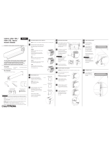
Lutron Roller 64 Regular-Roll Shades with 4-Inch Fascia
Chassis Mounting Guide for Roller 64 Regular-Roll Shades with 4-Inch Fascia. Please read before installing.
Lutron Electronics Co., Inc.
7200 Suter Road
Coopersburg, PA 18036-1299, U.S.A.
08/2023
P/N 045929 Rev B
Lutron, the Lutron logo, and Sivoia are trademarks of Lutron Electronics Co. Inc., registered in the U.S. and other countries.
English
For complete warranty information, refer to: lutron.com/TechnicalDocumentLibrary/Window Systems Warranty.pdf
* The self-drilling mounting
screws provided are suitable for
mounting into solid wood. It is the
responsibility of the installer to
select and install fasteners which
are appropriate for the mounting
surface such that each shade
bracket can support a load of
250 lbs (113.4 kg)
Cable should exit from the wall, header, or jamb on the drive side of system.
Leave 12–18 in (30–45 cm) of cable exposed.
2.1 Wall or Header Entry
If applicable, pre-drill the top back cover to allow clearance for
the entry of wiring without interfering with the bracket.
See the picture at right for examples.
IMPORTANT: The cable-entry hole
must be a minimum of 1.5 in (38 mm)
from the end of the top back cover to
avoid interference with shade bracket
installation, and large enough to allow
for adjustment during installation
without pinching the cable.
To ensure ample clearance between
wiring and the fabric roll:
• Wall entry should be as high
as possible.
• Header entry should be as close to
the wall as possible.
2.2 Jamb Entry
The shade bracket features a large
cutout for jamb-side cable entry
at the upper rear; no pre-drilling is
necessary. Use the bracket itself as
a template.
1 Prepare to Install
! CAUTION: RISK OF FALLING OBJECTS. Read and follow all instructions
for mounting the shade system. Failure to follow these instructions could
result in minor to moderate injury.
Important Notes: Please Read Before Installing
A. Lutron systems are intended for use with only Lutron brackets, controls,
and power supplies.
B. Codes: Install in accordance with all local and national electrical codes.
C. Environment: Ambient operating temperature: 32 °F - 104 °F
(0 °C - 40 °C), 0 - 90% humidity, non-condensing. Indoor use only.
D. The shade system must be mounted to blocking or other suitable
structural material. It is the responsibility of the installer to choose and
install fasteners that are appropriate for the mounting surface such that
each shade bracket can support a load of 250 lbs (113.4 kg).
E. Maintain sufficient clearance between the moving shade and any object.
F. Mount fixed controls and keep remote controls out of reach of children.
G. DO NOT operate shades if there are visible signs of wear or damage.
1.1 Lutron Items:
1.2 Additional Items You’ll Need:
#2 Phillips Screwdriver
1/4 in (6 mm) Hex-Head Driver
Tape Measure
Level
Power Drill
Lutron Roller 64 Regular-Roll Shade Shade Brackets
Bracket Mounting Screws
Shims
Cable Tie & Anchor
Top Back Cover optional
Fascia
Fascia Endcaps optional
At the drive end of the shade, the square mounting yoke is designed to fit over
the tabs on the shade bracket, and has a notch in each of its 4 sides.
a. Orient the shade as shown, so that the control buttons face toward the front,
accessible from the room side (left-drive shown).
b. Route the drive cable(s) up or down, using the upper and/or lower notches in
the mounting yoke to provide clearance.
2 Cable Entry
3.2 Mount the Shade Brackets
a. Mark the location of the shade brackets in the top back cover at the
bracket-to-bracket distance, centered over the window opening.
(Bracket-to-bracket distance = tube width + 1.5 in [38 mm]).
b. Position the left shade
bracket in the top back
cover as shown, aligning
it with the marks made
in step a. and install four
(4) mounting screws* in
each one, through the top
back cover, and into the
mounting surface (header
mount shown).
c. Repeat step b. to mount the second
shade bracket in the top back cover.
= Mounting Screw Top
Header
1.5 in
(38 mm)
Min.
Wall
Jamb
Header Mount
Wall Mount
24 in (610 mm) MAX
1.5 in
(38 mm)
MIN
Profile View
Cable Entry Examples
3 Installing with the Optional Top Back Cover
5 Orient the Control Buttons and Route the Drive Cable(s)
NOTE: If the installation does not include the optional top back cover, skip this
section and continue with section 4 Install the Shade Brackets
3.1 Mount the Top Back Cover
a. Verify that the mounting surface is level (header mount) or plumb (wall mount)
before attaching the top back cover.
NOTE: If the mounted top back cover is twisted or tilted, this could cause
fabric rub, telescoping, or rough/noisy operation. Shim if necessary. Add shims
between the mounting surface and top back cover only. DO NOT add shims
between the top back cover and brackets.
The top back cover features grooves that indicate recommended screw
placement, and help stabilize the point of your screw or drill bit.
b. Install two (2) mounting screws (not included) at each end, and at least one pair
(2 screws) for every 24 in (610 mm) of top back cover width.
IMPORTANT: Top back cover mounting screws must be installed a minimum
of 1.5 in (38 mm) from each end of the top back cover to provide clearance for
shade bracket installation.
Shade
Bracket
Top Back
Cover
Buttons
Facing
Front
Cable Route
Square
Mounting
Yoke
4 Install the Shade Brackets (without a Top Back Cover)
Bracket-to-Bracket Distance (Outside Mount)
Bracket-to-Bracket Distance (Inside Mount)
NOTE: If you mounted the top back cover and brackets according to the steps
in section 3 , skip this section and proceed directly to section 5 .
4.1 Mark the Shade Bracket Locations
Mark the location of the shade brackets so that they are level and centered
over the window, ensuring that the screws will be driven into a structural
member capable of supporting the operating load of the shade system.
• Bracket-to-bracket distance = tube width + 1.5 in (38 mm).
• DO NOT use the unmounted shade to determine the bracket location. Always
use the bracket-to-bracket distance to determine bracket location. There is an
idler spring that compresses* during shade installation, allowing the shade to fit
inside the bracket-to-bracket distance.
* IMPORTANT: At the correct bracket-to-bracket distance, idler compression
will be approximately 50% of its total travel.
• Allow ample clearance to prevent the fabric from rubbing against the trim,
window, top treatment, or any object. Wall mount may require spacer blocks
(not included), to clear the trim.
4.2 Mount the Shade Brackets
Install the shade brackets at the
marks made in step 4.1 using four
(4) mounting screws* in each one.
To ensure smooth, quiet shade
operation, verify that the mounted
shade brackets are plumb, level, and
aligned. Adjust as necessary, adding
shims (provided) to wall or header
mounted brackets, if required. Wall
Jamb
Header
* The self-drilling mounting
screws provided are suitable for
mounting into solid wood. It is the
responsibility of the installer to
select and install fasteners which
are appropriate for the mounting
surface such that each shade
bracket can support a load of
250 lbs (113.4 kg)
NOTE: Align the outside of the bracket with the edge of the top back cover.


