Page is loading ...

921709540
Thank you for choosing Rough Country for all your lighting needs.
Please read instructions before beginning installation. Check the kit hardware against the kit contents
shown below. Be sure you have all needed parts and know where they go.
If question exist, please call us @1-800-222-7023. We will be happy to answer any questions concerning the design,
function, and correct use of our products.
Tools Needed:
8mm Socket
3mm Allen wrench
15mm Socket
11mm Socket
Ratchet
Drill
1/4” Drill bit
Phillips Screwdriver
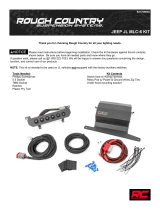
Kit Contents
(1)Fuse pod w/ mouting bracket
(1)Switch Bezel w/ Wiring Harness
(4) Allen Head Bolts
(4) Locking Nuts
(1) Relay Pod w/ Power & Ground Wires
Electrical Connectors
Zip Ties
Heat Shrink Tubing
97-01 Jeep XJ MLC-6 Kit

INSTALLATION INSTRUCTIONS
1. Park the vehicle on a smooth level surface.
2. Assemble the fuse panel on the mounting bracket with the fuse panel hardware if not already.
3. Remove the 4 bolts shown in Photo 1 using a 11mm wrench.
4. Secure the mounting bracket to the firewall with the stock hardware. Tighten using a 11mm wrench. See Photo 2.
5. On the inside of the vehicle, remove the two screws inside the center console. See Photo 3.
6. Pop up the shifter cover and remove the screw as shown in Photo 4.
7. Pop up the 4WD shifter plastic trim and remove the screw as shown in Photo 5.
8. Remove the ash tray. See Photo 6.
Photo 1 Photo 2
Photo 3 Photo 4
Photo 6 Photo 5
Remove bolts from firewall. Install the MLC-6 Bracket to firewall.
Remove the two screws Remove the screw
Remove screw Remove the ash tray from console

9. Place the switch bezel in the location the ash try was removed from. See Photo 7. Take care to keep the wires
away from harm as the switch bezel is installed. The wiring harness will be routed under the console and toward the
engine compartment to be connected with the MLC-6 fuse panel.
10. Using the bracket as a guide, drill the mounting holes using a 1/4” drill bit. See Photo 8. Take care not to damage
wires under the switch panel.
11. Install the supplied allen head bolts and lock nuts. See Photo 9. Tighten using a 3mm Allen wrench and 8mm sock-
et.
12. Reinstall the console with the stock hardware.
13. Route the hardness through the firewall and plug in the fuse panel and switch bank bezel.
14. Wire lights and other 12V accessories to the fuse panel. See Photo 11.
Photo 8
Attach accessory wires to relay pod.
Photo 10
Photo 7
Photo 9
Photo 11
Install the switch bezel Drill holes in console.
Install supplied bolts
Attach cover to relay pod.

By purchasing any item sold by Rough Country, LLC, the buyer expressly warrants that he/she is in compliance with all
applicable , State, and Local laws and regulations regarding the purchase, ownership, and use of the item. It shall be
the buyers responsibility to comply with all Federal, State and Local laws governing the sales of any
items listed, illustrated or sold. The buyer expressly agrees to indemnify and hold harmless Rough
Country, LLC for all claims resulting directly or indirectly from the purchase, ownership, or use of the
items.
AFTER INSTALLATION, YOU MUST START THE ENGINE TO ACTIVATE THE SYSTEM!
/


