Page is loading ...

JEEP JL MLC-6 KIT
921709630
Thank you for choosing Rough Country for all your lighting needs.
Please read instructions before beginning installation. Check the kit hardware against the kit contents
shown below. Be sure you have all needed parts and know where they go.
If question exist, please call us @1-800-222-7023. We will be happy to answer any questions concerning the design,
function, and correct use of our products.
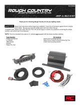
Kit Contents
Switch Pod w/ Wiring Harness
(2)Self Tapping Screws
Relay Pod w/ Power & Ground Wires
Zip Ties
Tools Needed:
Phillips Screwdriver
3/4” drill Bit or Step Bit
Drill Motor
7MM Socket
Plastic Pry Tool

1. Park the vehicle on a smooth level surface.
2. Using a 13mm socket, remove the two bolts closest to washer tank as shown in Photo 1 & 2. Retain the hardware
for re-use.
3. Position the fuse panel as shown in Photo 3 and secure with the factory hardware. Tighten using a 13mm wrench.
4. Locate the factory plastic cap in the fire wall on the drivers side about half way down the fire wall and remove it by
turning it. It will need to be drilled to allow the wiring harness to pass through it. See Photo 4.
5. Drill the cap using a step bit or comparable bit to 3/4” to allow the supplied grommet to be installed. See Photo 5.
(Note: Grommet is already installed on the wiring harness)
6. Install the power and ground leads to the fuse panel and tighten using a 10mm wrench. Do not over tighten the nut.
See Photo 6.
Photo 1 Photo 2
Photo 3 Photo 4
Photo 6 Photo 5
Remove bolt. Remove bolt.
Install fuse box with factory hardware Remove cap from fire wall
Drill 3/4” holt Route positive /ground to box and connect

7. Remove the control bezel by prying with a plastic pry tool on the passenger side. Take care not to damage sur-
rounding area or clips. See Photo 7.
8. Using a 7mm socket, remove the two bolts securing the screen bezel. See Photo 8.
9. Remove the bezel by prying with a plastic prying tool. See Photo 9.
10. Remove the Screen from the dash by removing the 4 screws as shown in Photo 10 using a 7mm socket. Take care
not to over extend the wiring on the screen or damage the screen.
11. Remove the plastic mat in the upper storage location on dash. It will be modified and re-installed in a later step. See
Photo 11.
12. Place the lower bracket on the dash and center the bracket. Mark the area to be drilled. Drill the hole using a 1 1/2”
short shanked hole saw. The hole is more easily drilled with 90degree drill. If not available, a center hole can be
drilled and the hole cut and gradually enlarged to allow the plug to pass through. Take care not to damage or cut
any wires below the dash. See Photo 12.
Photo 8
Remove fasteners securing screen
Photo 10
Photo 7
Photo 9
Remove the panel Remove fasteners securing bezel
Remove bezel
Photo 11 Photo 12
Remove the plastic liner Drill hole to route wiring

13. Using the bracket as a guide. Mark the plastic removed from the storage area and cut as shown to allow the wire to
pass through. See Photo 13.
14. Install the plastic in the dash and place the bottom of the switch housing in place. Install the supplied screws to se-
cure the bracket to the dash. See Photo 14.
15. Route the wire behind the dash and toward the drivers side.
16. Secure the top of the switch panel to the base with the supplied screws. Tighten using a phillips head screwdriver.
See Photo 15.
17. Install the wire through the plastic fire wall cap and install in the fire wall. See Photo 16.
18. Reinstall the screen and bezel with factory hardware. Tighten using a 7mm socket. See Photo 17 & 18.
19. Reinstall the climate and radio control bezel.
20. LED lights can now be wired to the fuse panel under the hood.
Photo 15 Photo 16
Photo 13 Photo 14
Cut plastic liner Install the lower bracket
Secure top to base. Route wires through cap and fire wall
Photo 17 Photo 18
Reinstall the screen Reinstall the bezel
By purchasing any item sold by Rough Country, LLC, the buyer expressly warrants that he/she is in compliance with all
applicable , State, and Local laws and regulations regarding the purchase, ownership, and use of the item. It shall be
the buyers responsibility to comply with all Federal, State and Local laws governing the sales of any items listed, illustrat-
ed or sold. The buyer expressly agrees to indemnify and hold harmless Rough Country, LLC for all claims resulting di-
rectly or indirectly from the purchase, ownership, or use of the items.
AFTER INSTALLATION, YOU MUST START THE ENGINE TO ACTIVATE THE SYSTEM!
/


