6
The next two lines display the current status of the sensor—
whether it is currently registering as occupied and whether it is
currently in Normal Hours or After Hours mode.
Load Tracking
If the sensor is bound to a room controller, this should always
be set to “Yes”. This allows for the sensor to understand which
loads are ON/OFF in order to properly manage presentation
mode, and create error messages in the event that the sensor is
not bound to any loads.
If the sensor is bound to a panel, this should be set to “No”. For
panels, the Load IDs are not handled the same way. Instead
of the sensor telling the panel which loads should turn on and
when, the panels listen for certain MAC addresses from the
sensors in order to determine if that sensor should control its
loads.
Follows AH
If this is set to “No”, the sensor will ignore After Hours settings
use the Normal Hours settings all the time.
NH Delay
The amount of time the load remains ON after no motion is
detected, during Normal Hours.
AH Delay
The amount of time the load remains ON after no motion is
detected, during After Hours.
NOTE: Set the analog occupancy sensor to minimum time delay.
The LMIO-201 digital time delay will be added to the
minimum sensor time delay. So for example, if a sensor
has a minimum time delay of 15 seconds and the LMIO-
201 is set to 20 minutes, as in the screenshot above, the
total delay time will be 20 minutes and 15 seconds.
LOAD CONFIGURATION (PNL)
Use the Load Configuration function to identify which load
numbers have been assigned to which fixtures, view and change
load parameters and load bindings to sensors. After selecting
Load Configuration (PnL), also known as
Push n’ Learn™, point the LMCT-100-2 at any IR enabled DLM
Local Network device and press Select.
Although PnL can be entered by pressing (and holding for three
seconds) the Configuration button on a DLM device in the room,
using the LMCT-100-2 provides access to additional parameters.
Important: To configure load binding from the LMCT-100, it
must be initiated by the LMCT-100. After entering PnL you must
exit before using the system.
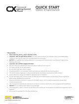
Update firmware on
l oad device to
utilize all settings
Press ‘Select’ to proceed
Sensor Configuration
Load Config (PnL)
Daylighting Config
Button Configuration
Dimming Configuration
More
=
BAT
When the device receives the signal from the LMCT-100, the
DLM Local Network goes into PnL mode; the red LED on all
communicating devices starts blinking at 2x/second and all loads
turn OFF except Load 1, which turns ON.
NOTE: If the room controller has an older version of firmware
installed which does not support newer features in the
LMCT-100, you will see a warning message. Firmware
in the room controller can be updated using the
LMCS-100 software.
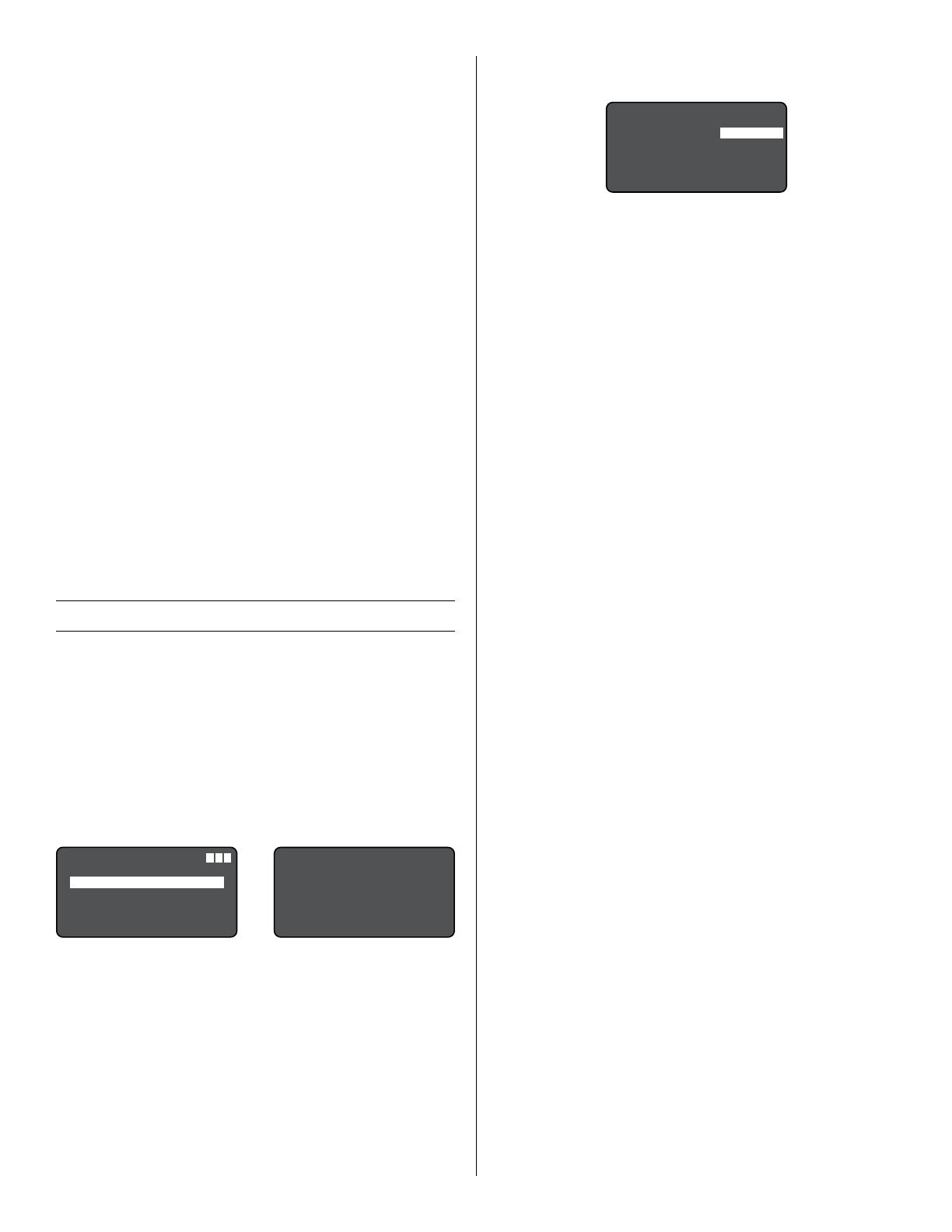
Load Selection
Settings for load 1 appear first.
Load Config <PnL>
Load: 1
Operation: <Auto On>
Blink: <Disable>
Load Type: <NonDim>
SEND BIND NEXT EXIT
Push to highlight NEXT and push the SELECT button to turn
ON the next load and view its settings.
Once the Load is selected, you can bind a button to the load by
pressing that button. Use the BIND option on the screen to bind
sensors to a load (this prevents having to access the button on
a sensor placed in a hard to reach spot). The BIND function will
toggle the sensor’s blue LED from on to off to indicate that the
sensor no longer controls this load.
Operation
The operation mode determines if the load will be turned
on automatically by a sensor, or only manually by a switch.
Available values: “Auto On”, “Manual On”.
Blink
The Blink Warning flashes the load OFF then ON one minute
prior to the sensor automatically turning the load OFF when the
time delay expires.
Available values: “Disable”, “Enable”.
Load Type
NOTE: Different values will appear based on the type of
controller. For example, if the controller is not capable of
dimming, the <0–10V> value will not appear.
• NonDim – Indicates a switched load. Note that if a load is
capable of dimming, selecting this value will not prevent the
load from dimming.
• 0–10V – Indicates a dimmed load.
• Pulsed+ – When this value is selected, and On value for
the controller will trigger the load for a specified amount
of time and then turn Off. This is useful for integration with
non-DLM devices. Some hardware only need a momentary
pulse to initiate a change (like a motorized lift for instance).
By setting the pulse time to 1 second, when a DLM button is
pressed, the lift will get the signal it needs to initiate it’s task.
Another example would be motorized shades. If it takes about
5 seconds to raise/lower the shades you would set to pulse
for 5 seconds. Then when a connected button is pressed, the
load turns on for 5 seconds and then turns off automatically.
• When “Pulsed+” is selected, press Select to display the
Pulsed Load Menu (shown below).
NOTE: This feature requires firmware versions of 6.17 or
later for the LMRC-111/112, or 6.29 or later for all
other room controllers.
• HID – This turns off the Blink Warn feature. It is intended for
use with loads High Intensity Discharge loads, since they
cannot immediately turn back on after turning off.
• AS-100 – This value is for use with the AS-100 Automatic
Control Switch. The AS-100 is a switch that controls the line
voltage (instead of sending a low voltage control message to
the room controller). Instead, the AS-100 responds to timed
power interrupt signals coming from the controller, providing
automatic shutoff with a blink warning when transitioning
between normal hours and after hours. Other timed interrupt
signals can turn the power on or off.
• Incand – Applies to LMRC-22x controllers only. This should
be used with Incandescent, Magnetic Low Voltage, Cold
Cathode, or Neon ballasts. It provides a direct (straight
line) reduction of voltage from 100% to minimum, with a
commensurate reduction of light from the fixture.