Page is loading ...

20'
- 01- -03-
-02-
DESCRIPTION
SC-SWSDU-W
SC-SWSDU-W
Occupancy/Vacancy
Voltage ................................................................ 120/277VAC,50/60Hz
Motor ................................................1/4HP-120VAC,50/60Hz
Adjustment Time Delay ............................................... 15Sec to 30Mins
SPECIFICATIONS
Multi-Technology PIR/Ultrasonic
INSTALLATION INSTRUCTIONS
Light Level Adjustment ............................... 100 Lux --daylight(trimpot)
Operation Temperature .................................................... 32° F--131°F
Incandescent .................................. 800W-120VAC,50/60Hz
Load Requirements:
Walk-Through Mode ..................... 3 minutes if no activity after 30 sec.
Test Mode ..................... 15 sec. at initial power up or DIP switch reset
Single Relay Pole Wall Sensor Switch
(2-IN-1)
Ultrasonic Adjustment .........................
INSTALLATION
Turn off the circuit breaker before installation.
WARNING:
Do not exceed electrical ratings.
Black lead to
Line(Hot), Red lead to Load wire, White lead to
4. Gently position wires in wall box, attach sensor switch to the box.
3. Mount device “TOP” up.
5. Restore power at circuit breaker or fuse, wait one minute.
7. Locate the adjustment trimpots on the control panel to perform
Indoor use only.
Wiring Diagram:
Figure 1
2. Connect lead wires according to wiring diagram (see Figure 2.)
6. Remove the small cover plate. (see Figure 3.)
8. Replace the small cover plate after testing and adjustment.
test and adjustment. (see Figure 3 and 4.)
Neutral wire, Green
lead to Ground.
Minimum to Maximum (trimpot)
PIR Adjustment ............................................. High or Low (DIP switch)
1. Make sure that the power has been turned OFF at the circuit
breaker.
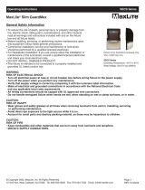
COVERAGE PATTERN
40'
TOP VIEW
10'
20'
10'
20'
5'
4'
Neutral
White
Hot
Black
Ground
Green
Load
Red
Neutral
Load
Figure 2
Figure 3
OFF OCC VAC
14
23
14
23
LIGHT
ULTRASONIC
OFF OCC VAC
Mode
Position
Left
Center
Right
(OCC)
Occupancy
(VAC)
Vacancy
Description
Switch Position:
(OFF)
Off Mode
Figure 4
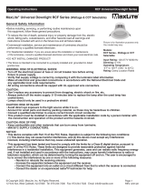
Default position: Daylight (100% at position 4)
Adjustable: Daylight to 100Lux (Counter clockwise)
Ambient Light Level Adjustment Trimpot
Control Panel Cover
Mounting Yoke
ULTRASONIC
LIGHT
PIR Lens
Ultrasonic Cones
Detection LEDs
Red=PIR
Blue=Ultrasonic
PIR Coverage: 1200 ft
Ultrasonic Coverage: 400 ft
2
2
Ultrasonic Sensitivity Adjustment Trimpot
Default position: Center at 65%
Adjustable: 30% (Position 1) to 100% (Position 4)
Note: Turn toward right for greater room space.
Turn toward left to avoid false alert in smaller room and near
the door way or heat source.
ADJUSTMENT
White
Fluorescent ....... 800VA-120VAC,1600VA-277VAC,50/60Hz
ON
OFF
1 2 3 4 5 6 7
SIDE VIEW
The SC Series wall switch sensor provides a simple and cost-effective
standalone solution which utilizes dual technology PIR (Passive
Infrared) and Ultrasonic to turn lights ON and OFF based on occupan-
cy/vacancy. The vandal resistant lens provides major and minor
movement detection coverage with a 180° field-of-view sensor. The
sensor wall switch can be used to meet many of the Title 20/24,
ASHRAE 90.1, and IECC code requirements.
Circuit is permanently open. Switch disabled.
Load will not react to the push button.
Occupancy Mode:
Automatic ON/OFF, time delay programmed
with Time Delay dipswitch setting (15 seconds -
30 minutes). See Time Delay table setting below
Vacancy Mode:
Manual ON/ Automatic OFF, time delay programmed
with Time Delay dipswitch setting (15 seconds -
30 minutes). See Time Delay table setting below
NEUTRAL REQUIRED

Figure 5
-06-
-05-
-04-
WARRANTY INFORMATION
MaxLite offers a 5 year warranty on this product, please see:
http://www.maxlite.com/resources/warranties for more information.
INSTALLATION INSTRUCTIONS
OPERATION
TROUBLESHOOTING
Sept. 2022
5 Minutes
Walk Through
PIR Sensitivity
50%
100%
Disabled
Enabled
Time Delay
15 Sec/Test
10 Minutes
15 Minutes
20 Minutes
25 Minutes
30 Minutes
1
7
456
=OFF =ON =Factory Setting
DIP SWITCH SETTING
By Pushing the Control Panel Cover, the Load can be turned On/Off
Manual On/Off Button:
Turning On the Load under Occupancy Mode:
Load to be Automatic On once occupancy detected.
Turning On the Load under Vacancy Mode:
Manual On/Off Button has to be pushed to turn On the Load.
Automatic Turning Off the Load:
Manual Turning Off the Load:
under either OCC or VAC mode. (illustrated as Figure 5)
Under VAC Mode, the Load can turn On automatically if motion detected
within the first 3 minutes.
By Manual On/Off Button, the Load can be turned Off under either OCC
or VAC mode.
Under either mode, the Sensor keeps the Load On until no motion is
detected plus the set time delay, load(s) to be Off automatically.
to 15s
(Test Mode), make sure there is no motion (no LED
was detected. To verify proper operation, turn the Time Delay Switch
Initial run:
The Load is out of control (frequently flashing):
1. It can take up to one minute for initial run.
2. Check the wiring connections, especially the Neutral Wiring.
The Load does not turn On without LED flashing or LED flashing
1. Push Manual On/Off Button, if the load turns On, verify that Sensitive
Range is on high. If the Load does not turn On, go to Step 2.
2. Check the wiring connections, especially Hot line and Neutral wiring.
The Load does not turn On while LED flashing with
motion detected:
1. Check to see if Ambient Light Level is enabled by covering the lens
2. Push Manual On/Off Button, if the load turns On, verify that Sensitivity
Range is on high. If the Load does not turn On, go to Step 3
3. Check the wiring connections, especially Hot Line and Neutral wiring.
The Load does not turn Off:
1. There can be up to a 30 minutes time delay after the last motion
regardless of motion:
2. Check the wiring connections, especially the Neutral wiring to the
The Load turns On while no desired:
1. Switch from OCC to VAC mode.
by hand.
flashing), the
Load should turn Off in 15 seconds.
sensor switch.
2. Reduce the Sensitivity Level to avoid false alert in smaller room
and near the door way.
PIR Sensitivity setting: Switch 1
Time Delay: Switches 4, 5, 6
The sensor will hold the lights on as long as occupancy is detected.
starts when no motion is detected. After
Walk-through mode: Switch 7
Turns the lights off three minutes after the area is initially occupied,
the first 30 seconds. If motion continues
The time delay countdown
no motion is detected for the length of the time delay, the sensor will
turn the lights off.
if no motion is detected after
beyond the first 30 seconds, the selected time delay applies.
Trigger Mode: Switches 2, 3
The sensor has 4 trigger options, set with DIP switches 2 and 3.
In the trigger mode DIP switch setting table:
require motion detection by the PIR and the Ultrasonic.
require motion detection by only one technology.
require motion detection by the PIR.
Both
Either
PIR
-time is more than 3 minutes, the sensor switch returns to normal
after 3 minutes. However, when set-time is less than 3 minutes,
the sensor switch returns to normal until set-time finished.
Under OCC Mode, if you press manual On/Off button first,when set-
Note: Only when there is no motion is detected during the
set-time period, the sensor switch returns to normal.
1 Minute
Trigger Mode
Initial
Trigger Load Output
Maintain Re-trigger 23
Both Either Either
PIR PIR PIR
Both Both Both
US
Option 1
Option 2
Option 3
Option 4
require motion detection by the Ultrasonic.
US
US US
The SC-SWSDU-W has 7 DIP switches under the cover. They
are used to set sensitivity, time delay, trigger mode, walk through
mode feature settings.
The SC-SWSDU-W is programmed independently for either
Occupancy Mode or Vacancy Mode as refer to the Band Switch
position under the control panel cover.
For proper operation, the SC-SWSDU-W has to consume power
from a hot and neutral. (Secured neutral wiring is required.)
The SC-SWSDU-W needs initial run within one minute. During the
initial run, the load might be turned On and Off several times.
The Time Delay Switch is default set on 15 seconds, do not adjust
it until initial run is finished and proper operation function
confirmed.
50%: SC-SWSDU-W coverage reduced to half the widest range.
Maximum PIR coverage range is 1200 square feet. (Refer to
Figure 1 "coverage pattern").
/