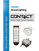
LMCT-100-2 Wireless Configuration Tool

Legrand LMCT-100-2 Wireless Configuration Tool User guide

  • Hello! I am an AI chatbot trained to assist you with the Legrand LMCT-100-2 Wireless Configuration Tool User guide. I’ve already reviewed the document and can help you find the information you need or explain it in simple terms. Just ask your questions, and providing more details will help me assist you more effectively!
Wattstopper
®
DLM Wireless IR Configuration Tool with USB
User Guide
No: 25791 – 07/18 rev. 3
Catalog Numbers • Les Numéros de Catalogue • Los Números de Catálogo: LMCT-100-2
Country of Origin: Made in China • Pays d’origine: Fabriqué en Chine • País de origen: Hecho en China
LMCT-100-2-U is BAA and TAA compliant (Product produced in the U.S.)
CONTENTS
Using the LMCT-100-2 ............................................................. 3
Batteries ...................................................................................3
Navigation ................................................................................ 3
Home Menu ........................................................................ 3
Sensor Configuration ..............................................................4
Current Settings ................................................................. 4
Adjusting Sensor Parameters ............................................ 4
Test Mode ........................................................................... 4
Sensor Testing – Individual Sensor .................................... 5
Sensor Testing – All Sensors on Bus ................................. 5
Saved Configurations .............................................................5
Configuring Analog Sensors ..................................................5
Load Configuration (PnL) ....................................................... 6
Load Selection ................................................................... 6
Pulsed Load Menu ............................................................. 7
Send ................................................................................... 7
Bind .................................................................................... 7
Next .................................................................................... 7
Exit ..................................................................................... 7
Daylighting Configuration ......................................................7
Specific Photosensor ......................................................... 7
Search Photosensor ........................................................... 7
Zone Setup (LMLS400/LMLS-600 Only) ............................ 8
Zone Setup (LMLS-500 Only) ............................................ 9
Calibration (LMLS-400 Only) ............................................ 10
Calibration (LMLS-500 Only) ............................................ 11
Calibration (LMLS-600 Only) ............................................ 11
Zone Settings (LMLS-400 Only)....................................... 12
Zone Settings (LMLS-500 Only)....................................... 13
Zone Settings (LMLS-600 Only)....................................... 13
Switched, Bi-Level, or Tri-Level ........................................ 13
Advanced Settings (LMLS-400 only) ............................... 14
Advanced Settings (LMLS-500 only) ............................... 14
Advanced Settings (LMLS-600 only) ............................... 15
Control Mode .................................................................... 15
Button Configuration ............................................................16
Load Button Parameters .................................................. 16
Scene Button Parameters ................................................ 16
Rocker Button Parameters ............................................... 17
Group Button Parameters ................................................ 17
Assign Loads .................................................................... 17
Dimming Configuration ........................................................17
Dimming Load Parameters .............................................. 18
Switched Load Parameters .............................................. 18
Adjust Light level ..................................................................18
Global Network ...................................................................... 18
Network Settings .............................................................. 19
Network Status ................................................................. 19
Utilities....................................................................................20
Smart Wire ....................................................................... 20
Identify Devices ................................................................ 20
Force System into PnG .................................................... 20
2
Room Mode ...................................................................... 20
Load Shed ........................................................................ 20
Status ............................................................................... 21
Load Status ...................................................................... 21
Group Status .................................................................... 22
Light Level ........................................................................ 22
Occupancy Sensor Status ................................................ 22
Panel Setup ............................................................................23
Location Settings .............................................................. 23
Date and Time ..................................................................23
Panel Programming ......................................................... 23
Schedules ........................................................................ 23
Holidays ........................................................................... 24
Panel Status ..................................................................... 24
Group Setup ...........................................................................24
Group Loads .................................................................... 24
Using the Smartwire Feature ........................................... 25
Defining Custom Group Parameters ................................ 25
Group Occupancy Sensor Settings .................................. 26
Group Dark/Light Events .................................................. 26
Troubleshooting .................................................................... 27
LMLS-400 / LMLS-500 Daylighting Control ..................... 28
Appendix – Updating the Firmware in the LMCT-100-2 ..... 29
Installing Firmware in the LMCT-100-2 ............................ 29
3
The (Home) button
takes you to the main
menu. The
(Back)
button can be thought
of as an undo function.
It takes you back one
screen. Changes that
were in process prior to
pressing the
button
are lost.
Home Menu
The Home (or Main) menu
displays after the power-up
process completes. It contains
information on the battery status
and six menu choices. Press
up/down buttons to locate the
desired function then press
Select.
A second Main Menu contains
additional Functions. Scroll
down to More and press Select
to view them.
Press Select More on the second screen to return to the first
group of options.
For most options, when you press Select, a message appears
on the screen telling you to point the LMCT-100-2 at a DLM
device and press Select again. This establishes communication
between the LMCT-100-2 and DLM devices.
For an occupancy sensor, the message tells you to point at the
specific sensor you want to configure.
Point and
Press Select
Point to desired
Occupancy Sensor
Press ‘Select’
For other devices, such as room controllers, which have no IR
sensor, the message tells you to point at any IR enabled device
in the DLM network.
Point to any IR
enabled device on
the network
Press ‘Select’
For buttons and paddles, the process involves an extra step
of pressing the particular button on the device, as described in
“Button Configuration” on page 16.
Once you make any changes and send the changes back to the
device, you must repeat the process of pointing at the device
and pressing Select.
USING THE LMCT-100-2
The LMCT-100-2 Digital Configuration Tool is a hand-held
tool for setup and testing of Wattstopper Digital Lighting
Management (DLM) devices. It provides wireless access to
occupancy and daylighting sensors for setup and parameter
changes, Wattstopper Push n’ Learn™ (PnL) technology for
load configuration, switch and dimmer assignment and operating
parameter changes. The LMCT-100’s display shows menus and
prompts to lead you through each process. The navigation pad
provides a familiar way to navigate through the customization
fields. The LMCT-100-2 allows modification of the system
without requiring ladders or tools and can be done simply with a
touch of a few buttons.
The LMCT-100-2’s IR transceiver allows bidirectional
communication between DLM devices and the LMCT-100.
Simple menu screens let you see the current status of the
system and make changes. It can change any of the DLM
occupancy sensor parameters such as sensitivity, time delay
and more. With the LMCT-100-2 you can also change load
configurations, without any new wiring. The LMCT-100-2 can
change dimming system options such as scene assignments,
fade rates and other options not available through the standard
user interface. Additionally, the LMCT-100-2 can be used for
initial configuration of the LMLS-400, LMLS-500, and LMLS-600
daylight sensors.
BATTERIES
The LMCT-100-2 operates on three
standard 1.5V AAA Alkaline batteries
or three rechargeable AAA NiMH
batteries.
The battery status displays in the
upper right corner of the display.
Three bars next to BAT= indicates a
full battery charge. A warning appears
on the display when the battery level
falls below a minimum acceptable
level. To conserve battery power, the
LMCT-100-2 automatically shuts off 10
minutes after the last key press.
NAVIGATION
You navigate from one field to another using (up) or (down)
arrow keys. The active field is indicated by flashing (alternates
between yellow text on black background and black text on
yellow background).
Once active, use the Select
button to move to a menu or
function within the active field.
Value fields are used to adjust
parameter settings. They are
shown in “less-than/greater-than”
symbols: <value>. Once active,
change them using
(left) and
(right) arrow keys. The
left key decrements and the
right key increments a value.
Selections wrap-around if you
continue to press the key beyond
maximum or minimum values.
Moving away from the value field
(using / keys) overwrites the
original value.
NOTE: When the bottom line of the screen contains commands
(such as SEND, SAVE, RECEIVE, etc.), both the left/right
and up/down buttons will move between the commands.
Sensor Configuration
Load Config (PnL)
Daylighting Config
Button Configuration
Dimming Configuration
More
Home/
Main Menu
Up
Select
Down
Right/Next
Left
Back
Power
On/Off
IR Window
BAT=
Sensor Config
Time Delay: <20 min>
PIR Sens: <90%>
US Sens: <70%>
Trigger : <PIR Only>
Retrigger: <PIR Only>
Walkthru: <Off>
SEND SAVE RECEIVE
Value FieldsParameters
Function Fields (on Home Menu)
Sensor Configuration
Load Config (PnL)
Daylighting Config
Button Configuration
Dimming Configuration
More
=
BAT
Select
Button
Up or Down
Button
Sensor Configuration
Load Config (PnL)
Daylighting Config
Button Configuration
Dimming Configuration
More
=
BAT
Adjust Light Level
Global Network
Utilities
Panel Setup
Group Setup
More
More
=
BAT
Press
Select
Press
Select
Sensor Configuration
Load Config (PnL)
Daylighting Config
Button Configuration
Dimming Configuration
More
=
BAT
4
SENSOR CONFIGURATION
Sensor Configuration
Load Config (PnL)
Daylighting Config
Button Configuration
Dimming Configuration
More
=
BAT
The Sensor Configuration menu includes options to view the
current settings of an specific sensor, make changes, and send
them back to the sensor. You can save those settings and then
send the same settings to another sensor, which provides a
quick way to configure multiple sensors. Additionally, a test
option shortens the delay time, when performing a sensor
walk test to define the optimum sensitivity settings and product
orientation.
Current Settings
Sensor Configuration
Current Settings
Test Mode
Saved Configurations
Analog Occ Sensor
After selecting this option, point the LMCT-100-2 at a specific
sensor and press Select. This enables communication between
the sensor and the LMCT-100. The sensor immediately sends its
current parameter settings.
The screen changes to show the current sensor settings where
you can adjust sensor parameters. “AH” next to Sensor Config
indicates that the sensor is currently in After Hours mode.
Changes made while AH is displayed only affect After Hours
operation.
Dual Sensor Config AH
Time Delay: <5 min>
PIR Sens: <80%>
US Sens: <70%>
Trigger : <PIR & US>
Retrigger: <PIR or US>
Walkthru: <Off>
SEND SAVE RECEIVE
NOTE: To program After Hours operation during normal
hours, you must force the room into After Hours mode.
Selection the Room Mode function in the Utilities menu
to switch between Normal and After Hours modes. Once
programming is complete, you can return the room to
Normal Hours mode. See “Utilities” on page 20 for
details.
Adjusting Sensor Parameters
On the Current Settings screen, you can view all parameters
applicable to the type of sensor that is currently communicating
with the LMCT-100. You can modify settings, send them to the
sensor, and/or store them in the LMCT-100.
NOTE: The screenshots in this section show a Dual Technology
Sensor. For Ultrasonic or PIR sensors, only the
appropriate parameters for that particular sensors are
displayed.
Dual Sensor Config
Time Delay: <20 min>
PIR Sens: <90%>
US Sens: <70%>
Trigger : <PIR Only>
Retrigger: <PIR Only>
Walkthru: <Off>
SEND SAVE RECEIVE
Time Delay
The amount of time the load remains ON after no motion is
detected.
Detection Sensitivity
PIR Sens – Sensitivity for the PIR detection. Setting the
sensitivity to zero (0) will disable PIR detection (Dual Tech
and PIR sensors only).
US Sens – Sensitivity for the ultrasonic detection. Setting
the sensitivity to zero (0) will disable ultrasonic detection in
the sensor (Ultrasonic sensors only).
Trigger/Retrigger Mode (Dual Tech Sensors only)
Trigger – Indicates whether to use PIR, Ultrasonic, Either,
or Both technologies for initial detection of occupancy. For
“Either”, the sensor will register occupancy if either of the
two technologies senses movement, whereas for “Both”,
both technologies must detect movement.
Retrigger – Indicates whether to use PIR, Ultrasonic,
Either, or Both technologies will be used to keep the lights
on once the sensor has initially been triggered. For “Either”,
the sensor will register occupancy if either of the two
technologies senses movement, whereas for “Both”, both
technologies must detect movement.
Walk Through Mode
Walkthru shortens the time delay to reduce the amount of
time the load is ON after a brief moment of occupancy, such
as returning to an office to pick up a forgotten item then
immediately exiting. When enabled, the load turns OFF three
minutes after the area is initially occupied if no motion is
detected after the first 30 seconds. If motion continues beyond
the first 30 seconds, the selected time delay applies.
Send
This sends the settings to the sensor. Highlight SEND and press
Select. Point the LMCT-100-2 at the Sensor and press Select
again.
The LEDs on the sensor blink to confirm the message has been
sent. To double-check that the new settings were sent to the
sensor, see “Receive.”
Save
This saves the settings in the LMCT-100-2 “Saved
Configurations” menu function for future use. Highlight SAVE
and press Select. The display shows the memory slot in which
the settings are saved. Each time you save a configuration
the “Memory Slot” number increases. You can save up to 9
configurations. Saved configurations are listed in the Saved
Configurations function in the Sensor Configuration menu
(see “Saved Configurations” on page 5).
Receive
This retrieves the current settings from the sensor.
Important: Selecting Receive before sending new settings to
the sensor or saving them to LMCT-100-2 memory clears any
value changes that you made.
Test Mode
In Test Mode, the sensor(s) in the room turn the load(s) off after
5 seconds and a 10 minute test period begins. During the test
period, the time delay is 5 seconds. This short time delay allows
performing a sensor walk test to define the optimum sensitivity
settings and product orientation. After the 10 minute period all
sensors return to normal operation mode. Or, select EXIT to
return them immediately.
After selecting Test Mode, you can select an individual sensor or
choose all sensors in the DLM network.
Sensor Test Mode
Individual Sensor
All Sensors on bus
Sensor Configuration
Current Settings
Test Mode
Saved Configurations
Analog Occ Sensor
5
SAVED CONFIGURATIONS
Use this feature to view the settings for any previously saved
configurations and send those settings to a sensor. Using this
feature, you can quickly configure multiple sensors with the
same settings.
Sensor Configuration
Current Settings
Test Mode
Saved Configurations
Analog Occ Sensor
Press
Select
Press
Select
Press the
Down Arrow for
Saved Configurations
Saved Sensor Configs
Pick DT Saved Config
<1 20/90/70/W >
RECALL DELETE
Deleted Sensor Config
in Memory Slot 2
Press ‘Select’
Point to desired Type
of Occupancy Sensor
to retrieve saved
configurations for
that sensor type
Press ‘Select’
Press
Select
Press
Select
To Review the Config
Settings Select
RECALL:
Press
Select
Press
Select
To Delete the Saved
Config Select
DELETE:
Press the
Right or
Left Arrow
to view other
Saved Configs
Saved Sensor Configs
Pick DT Saved Config
<2 5/80/70 >
RECALL DELETE
Saved Sensor Configs
Pick DT Saved Config
<2 5/80/70 >
RECALL DELETE
Dual Sensor Config
Time Delay: <5 min>
PIR Sens: <80%>
US Sens: <70%>
Trigger : <PIR & US>
Retrigger: <PIR or US>
Walkthru: <Off>
SEND SAVE
Press
Select
Press the
Down Arrow
for SAVE
Memory
Slot Number
(up to 9 per
sensor type)
Up to 4 enabled settings, e.g.:
20....Time Delay minutes
90....% PIR Sensitivity
70....% US Sensitivity
W...Walkthrough Enabled
Sensor Configuration
Load Config (PnL)
Daylighting Config
Button Configuration
Dimming Configuration
More
=
BAT
NOTE: If no saved configurations exist, you will see:
No Sensor Configurations exist, Press ‘Select’.
CONFIGURING ANALOG SENSORS
This option is used if you have an LMIO-201 connected to an
analog sensor, which allows limited control of the analog sensor
over DLM.
Sensor Configuration
Current Settings
Test Mode
Saved Configurations
Analog Occ Sensor
LMIO-201 0188743930
Sensor is Occupied
Sensor in NormalHours
Load Tracking: <Yes>
Follows AH: <Yes>
NH Delay: <1 Min>
AH Delay: <2 Min>
NEXT PRIOR SEND DONE
After selecting the Analog Occ Sensors, option, point the
LMCT-100-2 at any IR enabled device in the room. There
must be an LMIO-201 connected with an analog sensor wired
correctly to the LMIO-201, or you will receive an error. If the
LMIO-201 is connected and wired properly and you still receive
an error, press the Config button on the LMIO-201. This will
cause the LMIO-201 to join the local network again. Then try
selecting the option again.
Once connection is established, the LMIO-201 screen is displayed.
The top line shows the serial number of the LMIO-201.
Sensor Testing – Individual Sensor
Use this option to put an individual sensor into test mode. After
selecting Individual Sensor, point the LMCT-100-2 at that
sensor and press Select
NOTE: The screenshots in this section show a Dual Technology
Sensor. For Ultrasonic or PIR sensors, only the appropriate
parameters for that particular sensors are displayed.
When testing an individual sensor, the serial number of that
sensor is displayed on the second line of the screen.
Adjusting Sensitivity during Test
DT Sensor Test
(0171986806)
PIR Sens: <90%>
US Sens: <70%>
Detection : <PIR Only>
SEND RECEIVE EXIT
You can adjust sensitivity values while inside Test Mode. (The
new values must be sent to the sensor before they take effect.)
PIR Sens – Passive Infrared sensitivity
US Sens – Ultrasonic sensitivity
Values are 0 to 100%, in 10% increments.
Detection Criteria (Dual Technology Sensors only)
You can select to test one or the other technology, or both
technologies together. Available values: “PIR”, “US”, “PIR or
US”, “PIR & US”.
Send
If you change sensitivity or detection values, you must select
Send before they take effect. After the configuration is sent
press Select to return to the test menu.
Receive
Retrieves settings from the sensor so you can view or modify
them for further testing.
Exit
Exits test mode
Sensor Testing – All Sensors on Bus
When you select “All Sensors on bus”, you can test the selected
sensor along with other sensors on the DLM Local Network
(bus) to understand the coverage in the entire room.
6
The next two lines display the current status of the sensor—
whether it is currently registering as occupied and whether it is
currently in Normal Hours or After Hours mode.
Load Tracking
If the sensor is bound to a room controller, this should always
be set to “Yes”. This allows for the sensor to understand which
loads are ON/OFF in order to properly manage presentation
mode, and create error messages in the event that the sensor is
not bound to any loads.
If the sensor is bound to a panel, this should be set to “No”. For
panels, the Load IDs are not handled the same way. Instead
of the sensor telling the panel which loads should turn on and
when, the panels listen for certain MAC addresses from the
sensors in order to determine if that sensor should control its
loads.
Follows AH
If this is set to “No”, the sensor will ignore After Hours settings
use the Normal Hours settings all the time.
NH Delay
The amount of time the load remains ON after no motion is
detected, during Normal Hours.
AH Delay
The amount of time the load remains ON after no motion is
detected, during After Hours.
NOTE: Set the analog occupancy sensor to minimum time delay.
The LMIO-201 digital time delay will be added to the
minimum sensor time delay. So for example, if a sensor
has a minimum time delay of 15 seconds and the LMIO-
201 is set to 20 minutes, as in the screenshot above, the
total delay time will be 20 minutes and 15 seconds.
LOAD CONFIGURATION (PNL)
Use the Load Configuration function to identify which load
numbers have been assigned to which fixtures, view and change
load parameters and load bindings to sensors. After selecting
Load Configuration (PnL), also known as
Push n’ Learn™, point the LMCT-100-2 at any IR enabled DLM
Local Network device and press Select.
Although PnL can be entered by pressing (and holding for three
seconds) the Configuration button on a DLM device in the room,
using the LMCT-100-2 provides access to additional parameters.
Important: To configure load binding from the LMCT-100, it
must be initiated by the LMCT-100. After entering PnL you must
exit before using the system.
WAR NING
Update firmware on
l oad device to
utilize all settings
Press ‘Select’ to proceed
Sensor Configuration
Load Config (PnL)
Daylighting Config
Button Configuration
Dimming Configuration
More
=
BAT
When the device receives the signal from the LMCT-100, the
DLM Local Network goes into PnL mode; the red LED on all
communicating devices starts blinking at 2x/second and all loads
turn OFF except Load 1, which turns ON.
NOTE: If the room controller has an older version of firmware
installed which does not support newer features in the
LMCT-100, you will see a warning message. Firmware
in the room controller can be updated using the
LMCS-100 software.
Load Selection
Settings for load 1 appear first.
Load Config <PnL>
Load: 1
Operation: <Auto On>
Blink: <Disable>
Load Type: <NonDim>
SEND BIND NEXT EXIT
Push to highlight NEXT and push the SELECT button to turn
ON the next load and view its settings.
Once the Load is selected, you can bind a button to the load by
pressing that button. Use the BIND option on the screen to bind
sensors to a load (this prevents having to access the button on
a sensor placed in a hard to reach spot). The BIND function will
toggle the sensor’s blue LED from on to off to indicate that the
sensor no longer controls this load.
Operation
The operation mode determines if the load will be turned
on automatically by a sensor, or only manually by a switch.
Available values: “Auto On”, “Manual On”.
Blink
The Blink Warning flashes the load OFF then ON one minute
prior to the sensor automatically turning the load OFF when the
time delay expires.
Available values: “Disable”, “Enable”.
Load Type
NOTE: Different values will appear based on the type of
controller. For example, if the controller is not capable of
dimming, the <0–10V> value will not appear.
NonDim – Indicates a switched load. Note that if a load is
capable of dimming, selecting this value will not prevent the
load from dimming.
0–10V – Indicates a dimmed load.
Pulsed+ – When this value is selected, and On value for
the controller will trigger the load for a specified amount
of time and then turn Off. This is useful for integration with
non-DLM devices. Some hardware only need a momentary
pulse to initiate a change (like a motorized lift for instance).
By setting the pulse time to 1 second, when a DLM button is
pressed, the lift will get the signal it needs to initiate it’s task.
Another example would be motorized shades. If it takes about
5 seconds to raise/lower the shades you would set to pulse
for 5 seconds. Then when a connected button is pressed, the
load turns on for 5 seconds and then turns off automatically.
When “Pulsed+” is selected, press Select to display the
Pulsed Load Menu (shown below).
NOTE: This feature requires firmware versions of 6.17 or
later for the LMRC-111/112, or 6.29 or later for all
other room controllers.
HID – This turns off the Blink Warn feature. It is intended for
use with loads High Intensity Discharge loads, since they
cannot immediately turn back on after turning off.
AS-100 This value is for use with the AS-100 Automatic
Control Switch. The AS-100 is a switch that controls the line
voltage (instead of sending a low voltage control message to
the room controller). Instead, the AS-100 responds to timed
power interrupt signals coming from the controller, providing
automatic shutoff with a blink warning when transitioning
between normal hours and after hours. Other timed interrupt
signals can turn the power on or off.
IncandApplies to LMRC-22x controllers only. This should
be used with Incandescent, Magnetic Low Voltage, Cold
Cathode, or Neon ballasts. It provides a direct (straight
line) reduction of voltage from 100% to minimum, with a
commensurate reduction of light from the fixture.
7
HiLumApplies to LMRC-22x controllers only. This is used
for 2 wire dimming ballasts such as the Phillips Advance X.
These ballasts can’t use a straight line voltage reduction
because at some point there isn’t enough voltage to power
the electronics in the ballast itself. This value provides a
smaller range of voltage change, resulting in an output from
100% to minimum %.
MarkXApplies to LMRC-22x controllers only. This used
for 3 wire dimming ballasts that have both a dimming hot
wire and a switched hot wire, such as the HiLume fixtures.
Pulsed Load Menu
Pulsed Load Menu
Load: 1
Load Type: Pulsed
Pulse Seconds: <0>
DONE
This menu displays when “Pulsed’ is selected for the Load Type
and Select is pressed. Change the Pulse Seconds parameter
to set the length of the pulse. Then select DONE to return to the
Load Config <PnL> screen.
Send
To update the load parameters in the room controller, select
SEND, point the LMCT-100-2 at any IR enabled device, and
press Select again.
New settings are sent to the selected load. Wait 5–6 seconds
for the message to clear. You can then select another function
(BIND, NEXT, EXIT). To instantly end load configuration press
the HOME key.
Bind
This feature binds an occupancy sensor to the selected load.
After selecting BIND, point the LMCT-100-2 to a specific
occupancy sensor, and press Select.
You can repeat this process to bind more than one sensor to the
same load.
Next
Select another load. When NEXT is selected, Load 1 turns OFF
and Load 2 turns ON.
Exit
This ends the configuration function and exits PnL.
DAYLIGHTING CONFIGURATION
Daylighting Config allows you to setup daylighting and operation
parameters specific to the type of sensor that is communicating
with the LMCT-100. Different menu options are displayed
depending upon the device.
Once you select Daylighting Config, you select the model of
the sensor you want to configure.
Daylighting Config
LMLS-400
LMLS-500
LMLS-600
Sensor Configuration
Load Config (PnL)
Daylighting Config
Button Configuration
Dimming Configuration
More
=
BAT
Note regarding IR communication with the LMLS-600:
Because of the great mounting heights of skylight sensors in
high-bay applications, it is important to stand directly underneath
the sensor, with the LMCT-100-2 held in a vertical orientation
pointed at the bottom of the sensor.
In some cases, direct communications between the
LMCT-100-2 and the LMLS-600 may be difficult to achieve
due to interference from very high ambient light when looking
up, from direct sunlight, high intensity fluorescent fixtures
(e.g.,T5HO) mounted close to the sensor, as well as some other
intense light sources. In these cases, communications can
be established with the sensor by aiming the LMCT-100-2 at
another DLM product in the room with a visible IR window (e.g.,
a wall switch or occupancy sensor).
Refer to the specific LMLS installation instructions for details
about daylighting setup and operation of each of the models
listed below.
Once you select a particular model, you have two choices:
Specific Photosensor or Search Photosensor.
Specic Photosensor
Use this function if you are pointing the LMCT-100-2 directly at a
specific photosensor.
Press
Select
Daylighting LMLS-400
Specific Photosensor
Search Photosensors
Point to the desired
Photosensor and
press ‘Select’
Point and
Press Select
Serial number will be different
for each LMLS-400
LMLS-400 0293724909
Zone Setup
Calibration
Zone Settings
Advanced Settings
Control Mode
Search Photosensor
The Search Photosensor function allows you to identify which
LMLS device will be commissioned. After enabling and pointing
the LMCT-100-2 to any DLM device, a list of all photosensors
of the previously selected model in the DLM Local Network
appears on the screen. Each DLM device has its own serial
number. One advantage to this method is that you can point the
LMCT-100-2 at a switch or other easily accessible DLM device.
Daylighting LMLS-400
Specific Photosensor
Search Photosensors
Point to Any IR
enabled device on
the network
Press ‘Select’
Point and
Press Select
Press
Select
Choose
Search
Photsensors
Daylighting LMLS-400
‘Select’ a device ID
0293724909
Press
Select
Choose
Desired
Photsensor
Point to Any IR
enabled device on
the network
Press ‘Select’
Point and
Press Select
LMLS-400 Daylighting Menu
Serial number will be different
for each LMLS-400
LMLS-400 0293724909
Zone Setup
Calibration
Zone Settings
Advanced Settings
Control Mode
8
Zone Setup (LMLS400/LMLS-600 Only)
Selecting the Operating Mode
Zone Setup allows you to select and change the Operation
Mode of a zone, specify if a selected load is to be controlled by
Daylighting and to bind loads to the device. To configure zones
for the LMLS-500 refer to “Zone Setup (LMLS-500 Only)” on
page 9.
After choosing Zone Setup and pressing Select, the current
operation mode is displayed. Available values are: Switched,
Bi-Level, Tri-Level, or Dimmed.
Press
Select
LMLS-400 0293611935
Zone Setup
Calibration
Zone Settings
Advanced Settings
Control Mode
Zone Setup LMLS-400
Operation <Dimmed>
CONTINUE
Press Left/Right arrow to choose
the desired operation mode:
<Switched>, <Bi-Level>,
<Tri-Level> or <Dimmed>
Point and
Press Select
Zone Setup LMLS-400
Operation <Switched>
CONTINUE
Press
Select
Choose
CONTINUE
Point to any IR
enabled device on
the Network
Press ‘Select’
Switched
Switched mode provides ON/OFF switching within the
daylighting zone controlled by the photosensor.
Bi-Level
Bi-level mode provides three light levels within the daylighting
zone controlled by the photosensor by using 2 load circuits.
Load 1 - OFF
Of
f = 0%
Med = 50%
Max = 100%
Load 2 - OFF
Load 1 - ON
Load 2 - OFF
Load 1 - ON
Load 2 - ON
Tri-Level
Tri-level mode provides four light levels within the daylighting
zone controlled by the photosensor by using 2 load circuits.
Of
f = 0%
Low = 33%
High = 66%
Max = 100%
Load 1 - OFF
Load 2 - OFF
Load 1 - OFF
Load 2 - ON
Load 1 - ON
Load 2 - OFF
Load 1 - ON
Load 2 - ON
Dimmed
Dimmed mode provides continuous dimming within the daylight
zone controlled by the photosensor.
Load 1 - ON 1% 1%.
.
.
.
.
100%
Load 1 - ON 100%
Switched and Dimmed Load Assignment
The load binding process for Switched loads and Dimmed loads
is the same.
Load 1
Daylight Load: <No>
NEXT PRIOR DONE
Press Left/Right
arrow to choose
<Yes> or <No>
Depending on the Operation Mode,
the screen display will be Switched
or Dimmed
Load 1:
Zone Setup LMLS-400
Switched
To do load binding the load needs to be assigned as a Daylight
Load by selecting “Yes”.
Load 1
Daylight Load: <Yes>
NEXT PRIOR DONE
Zone Setup LMLS-400
Switched
Next
To continue to assign Daylight Load binding to load 2, choose
NEXT.
Point and
Press Select
Press
Select
Choose
NEXT
Load 2
Daylight Load: <No>
NEXT PRIOR DONE
Zone settings for the
next load are diplayed.
Zone Setup LMLS-400
Switched
Load 1
Daylight Load: <Yes>
NEXT PRIOR DONE
Zone Setup LMLS-400
Switched
Point to an IR
enabled device on
the Network
Press ‘Select’
9
Prior
To assign Daylight Load binding to the previous load, choose
PRIOR. This is similar to NEXT, but chooses the previous load.
This function behaves the same for all Operation Modes.
Done
When you have completed all load bindings, choose DONE.
This function behaves the same for all Operation Modes.
Bi-Level Load Assignment
To do load binding the load needs to be assigned as a Daylight
Load by selecting “Yes”. Next, Prior and Done function the
same as for Switched and Dimmed.
Load 1
Daylight Load: <No>
NEXT PRIOR DONE
Zone Setup LMLS-400
B i-Level
Load 1
Daylight Load: <Yes>
ON When: <Med &Max>
NEXT PRIOR DONE
Press Left/Right
arrow to choose
<Med & Max> or <Max>
Zone Setup LMLS-400
B i-Level
Press Left/Right
arrow to choose
<Yes> or <No>
For Load 1:
If <Yes> is selected, ON When appears
after scrolling down.
Tri-Level Load Assignment
To do load binding the load needs to be assigned as a Daylight
Load by selecting “Yes”.
Load 1
Daylight Load: <No>
NEXT PRIOR DONE
Load 1
Daylight Load: <Yes>
ON When: < Low &Max>
NEXT PRIOR DONE
Zone Setup LMLS-400
Tri-Level
Zone Setup LMLS-400
Tri-Level
Press Left/Right
arrow to choose
<Yes> or <No>
For Load 1:
Press Left/Right
arrow to choose
<Hi & Max> or
<Low & Max>
If <Yes> is selected, ON When appears
after scrolling down
Next, Prior and Done function the same as for Switched and
Dimmed.
Zone Setup (LMLS-500 Only)
Selecting the Operation Mode
Zone Setup allows you to select the number of zones, change
the operation mode of a zone, specify if a selected load is to be
controlled by Daylighting and to bind loads to the LMLS-500.
For each zone, the Operating Mode types are the same as for
the LMLS-400 and LMLS-600. See “Selecting the Operating
Mode” on page 8 for details.
Zone Setup LMLS-500
Number of Zones <3>
Choose the number of
Daylighting Zones
Press
Select
LMLS-500 0293724909
Zone Setup
Calibration
Zone Settings
Advanced Settings
Control Mode
Zone Setup LMLS-500
Number of Zones <3>
CONTINUE
Press Left/Right arrow to
select the number of Zones
(1, 2, or 3)
Point to Any IR
enabled device on
the network
Press ‘Select’
Choose the number of
Daylighting Zones
Zone Setup LMLS-500
Zone 1: <Bi-Level>
Zone 2: <Switched>
Zone 3: <Tri-Level>
CONTINUE
Pick a control type
for ALL Zones
Zone Setup LMLS-500
Bi-Level
NEXT PRIOR DONE
Point and
Press Select
CONTINUE
Press
Select
Choose
CONTINUE
Press Left/Right arrow to choose the
desired operation mode for each Zone:
<Switched>, <Bi-Level>,
<Tri-Level> or <Dimmed>
Point and
Press Select
Point to any IR
enabled device on
the Network
Press ‘Select’
Switched and Dimmed Load Assignment
The load binding process for Switched loads and Dimmed
loads is the same as it is for the LMLS-400 and LMLS-600.
However, instead of the Daylight Load parameter used when
programming those models, the LMLS-500 screen has a Zone
parameter. By default it is set to “None”. You must select a Zone
for the load.
Load: 1
Zone: <None>
NEXT PRIOR DONE
Press Left/Right
arrow to select
the Zone
Depending on the Operation Mode,
the screen display will be Switched
or Dimmed
Load 1:
Zone Setup LMLS-500
Switched
Once the zone is assigned, select NEXT to continue to the next
Load. Next, Prior and Done function the same as they do for
the LMLS-400. See the previous page for details.
Bi-Level and Tr-Level Load Assignment
Once again this load binding is the same as for the LMLS-400,
but the Zone parameter is displayed instead of Daylight Load.
You must select a Zone for the load.
Load 1: Press Left/Right
arrow to select
the Zone
Zone Setup LMLS-500
Bi-Level
NEXT PRIOR DONE
Load: 1
Zone: < None>
Load 1
Daylight Load: <Yes>
ON When: <Max>
NEXT PRIOR DONE
Press Left/Right
arrow to choose
a specific value
Zone Setup LMLS-500
Bi-Level
If
a Zone is selected, ON When
appears after scrolling down.
Once the zone is assigned, select NEXT to continue to the next
Load. Next, Prior and Done function the same as they do for
the LMLS-400. See the previous section for details.
10
Calibration (LMLS-400 Only)
Calibration establishes a relationship between the workplane
luminance and the light level measured by the sensor. This can
be done Automatically or Manually.
Automatic Calibration
Sensor Configuration
Load Config (PnL)
Daylighting Config
Button Configuration
Dimming Configuration
More
=
BAT
Press
Select
Press
Select
LMLS-400 0293611935
Zone Setup
Calibration
Zone Settings
Advanced Settings
Control Mode
Choose
Calibratio
n
LMLS-400 0293611935
Automatic Calibration
Manual Calibration
Main Menu
Lights will warm up
and rem ain ON for 2
min, then Auto
Calibration will take
2 more min to finish
Please wait 120 sec
Counts down from 120 second
s
then returns to the Main Menu; the
Automatic
Calibration process continues for 2 minutes,
with the controlled loads switching ON and OFF
,
then the sensor enters Test Mode for 5 minutes.
Calibrating LMLS-400
Automatic Calibration can be started by the LMCT-100, or by
pressing and holding the user pushbutton located in the sensor
head.
1. Complete all wiring and turn power on to the connected
room controller.
2. Press and hold the user button for at least 2 seconds then
release, or activate automatic calibration from the LMCT-100.
3. Blue LED will start flashing once every 4 sec.
4. Daylighting controlled loads will automatically turn ON for 2
minutes to allow controlled lamps to warm up and reach a
stable full output.
5. Remove any objects that may affect the LMLS-400 light
level reading (ladder or temporary objects).
6. Lights will cycle eight times for automatic setpoint selection.
7. The photosensor is in Test Mode when the blue LED starts
flashing once per second. For the next 5 minutes the
sensor will be in Test Mode.
8. Verify the setpoints automatically selected by the photo
sensor with the LMCT-100. If the automatic selected
setpoints are not acceptable, proceed to manual calibration.
Manual Calibration
LMLS-400 0293611935
Automatic Calibration
Manual Calibration
After selecting Manual Calibration, the display changes based
on the Operating Mode.
Switched, Bi-Level and Tri-Level
Choose a reference location within the daylighting zone that
is most likely to have the lowest light level when day lit and is
located farthest from the window.
Calibrating LMLS-400
Desired Light Level
at the workplane: <50fc>
Actual Light Level at
at the workplane: <35fc>
SEND
To set the On and Off Setpoints automatically to best match a
designed light level for the workplane, enter the desired level,
along with the present measured level (from a light meter),
and then press SEND, point the LMCT-100-2 at an IR enabled
device, and press Select..
Dimmed
For a dimmed Operating Mode, you must calibrate the LMLS-400
separately for Day and for Night.
Daylighting Config
(LMLS-400)
Choose setpoint
pre ss ‘Select
Setup: <Day>
Day Setup
Make this adjustment when there is enough daylight to provide
40% to 90% of the target light level. For example, if the target
is 40 footcandles, make this adjustment when the daylight
contribution is between 16 and 36 footcandles.
1. Press the Day button.
2. Using a light meter at the task surface, press the Up and
Down LMCT-100-2 arrows to adjust light levels.
3. Once the target level has been reached, press the Select
button to hold the value.
4. When Day and Night adjustments are complete, press
HOME to exit the calibration process and return to normal
operation.
5. To set the desired light level, point to the LMLS-400 and
continue pointing to it while pressing the / keys.
Thekey increments and thekey decrements the light
level.
Daylighting Config
(LMLS-400)
When done adjusting
pre ss Select
Day Setup
Press
Select
Press
Up/Down
arrow
Increment (raise)
Decrement (lower)
Daylighting Config
(LMLS-400)
D ay Setup
Use the Up/Down Keys
to set the desired
Day light level
Daylighting Config
(LMLS-400)
Incrementing the
Light level
Day Setup
Daylighting Config
(LMLS-400)
Day Setup
Day Setpoint Saved
Continue adjusting pressing the
Up or Down arrow until
desired Light Level is achieved
Night Setup
To set the desired light level, point to the LMLS-400 and
continue pointing to it while pressing the / keys. Thekey
increments and thekey decrements the light level.
11
Press
Select
LMLS-500 0293724909
Zone Setup
Calibration
Zone Settings
Advanced Settings
Control Mode
Choose
Calibration
Lights will warm up
and rem ain ON for
two minutes
Please wait 120 sec.
Counts down from120 seconds
then returns to the Main Menu
Enter light level for
ALL zones
Calibrating LMLS-500
Point to Any IR
enabled device on
the network
Press ‘Select’
Point and
Press Select
Take a light level
at Zone 1
Zone 1: 50fc
NEXT
Calibrating LMLS-500
(Full On)
Calibrating LMLS-500
(Full On)
Take a light level
at Zone 1
Zone 3: 50fc
NEXT
Press
Select
Choose
NEXT
Calibration (LMLS-600 Only)
The role of the calibration process is to establish, for the
controlled zone, the appropriate setpoint for operation, to learn
the dimming curves of the controlled loads, and to create an
initial daylight ratio for closed-loop versus open-loop sensors.
This can be done Automatically or Manually.
Automatic Calibration
Automatic Calibration can be started by the LMCT-100, a similar
menu in LMCS, or by pressing and holding the user pushbutton
(located on the bottom of the sensor, farthest from the RJ45
connection) for three seconds.
Sensor Configuration
Load Config (PnL)
Daylighting Config
Button Configuration
Dimming Configuration
More
=
BAT
Press
Select
Press
Select
LMLS-600 0293611935
Zone Setup
Calibration
Zone Settings
Advanced Settings
Control Mode
Choose
Calibration
Daylighting LMLS-600
Automatic Calibration
Manual Calibration
Main Menu
Please leave the area
and return after the
Blue LED stops
blinking
Press ‘Select’ to
continue or ‘Home’ to
cancel Auto Calibrate
Calibrating LMLS-600
NOTE: It is critical that, during the Automatic Calibration
process, the area under the sensor, as well as the
skylight area, remain free of any obstructions, and that
no changes occur (including human foot traffic) within
the cone-of-view of the closed loop sensor. Please clear
the area before starting the Automatic Calibration, and
wait for the calibration completion (when the blue LED
stops flashing once every 4 seconds) before reentering
the area.
Daylighting Config
(LMLS-400)
Night Setup
Night Setpoint Saved
Press
Up/Down
arrow
Increment (raise)
Decrement (lower)
Daylighting Config
(LMLS-400)
Night Setup
Use the Up/Down Keys
to set the desired
Day light level
Daylighting Config
(LMLS-400)
Incrementing the
Light level
Night Setup
Continue adjusting pressing the
Up or Down arrow until
desired Light Level is achieved
Daylighting Config
(LMLS-400)
When done adjusting
pre ss Select
Night Setup
Press
Select
When Day and Night adjustments are complete, press the HOME
key to terminate Manual Calibration and return to normal operation.
Calibration (LMLS-500 Only)
Calibration allows you to establish a relationship between
the workplane luminance and the measured daylight at the
photocell.
Light Level at Photocell
0
20
40
60
80
100
0 500 1000 1500 2000
1750
70
Light Level at Task
Use the LMCT-100-2 for the Calibration process.
1. Complete all wiring and turn power ON to the connected
room controllers.
2. Select the LMLS-500 to be calibrated using the LMCT-100.
3. Select Calibration. For each Zone, choose a reference
location that is most likely to have the lowest light level
when day lit for each zone.
4. With the electric lights ON, use a light meter to measure
the light level in each zone.
5. Enter the measured light level at the task surface per zone,
in the LMCT-100.
6. Daylighting controlled loads will turn OFF.
7. Use a light meter to measure the light level in each zone.
8. Enter the measured light level at the task surface per zone
in the LMCT-100.
9. Select the Send button to establish communication with
the LMLS-500.
12
The Calibration process consists of:
Pausing for 15 seconds to allow the user to vacate the area
under the sensor.
Turning off all configured loads, for about 10 seconds, to
compute an initial daylight ratio.
Warming up the controlled loads, at maximum level,
until they reach full output (typically, this requires several
minutes).
Switching or Fading the level of the controlled loads from
maximum to minimum level very slowly (over approximately
two minutes) while observing both sensors, to determine the
ballast curve.
Turning the controlled loads off completely, and observing
both sensors for several seconds, to calculate daylight
ratios..
Validating the data collected, and marking the sensor
as calibrated (and active) if a good calibration has been
established. If the calibration should fail, the LEDs will revert
to showing an “Awaiting Calibration” state and the process
must be repeated.
Manual Calibration
Manual Calibration allows you to refine the setpoint for the
controlled zone.
Press
Select
Press
Select
LMLS-600 0293611935
Zone Setup
Calibration
Zone Settings
Advanced Settings
Control Mode
Choose
Manual
Calibration
Choose
Calibration
Daylighting LMLS-600
Automatic Calibration
Manual Calibration
NOTE: Even if you wish to refine the setpoints using the
Manual Calibration feature, you MUST first complete
an Automatic Calibration to establish the other critical
installation parameters.
Choose a reference location within the daylighting zone that
is most likely to have the lowest light level when day lit and is
located farthest from the window.
Point to any IR
enabled device on
the network
Press Select
Calibrating LMLS-600
Desired Light Level
at the workplane: <50fc>
Actual Light Level at
at the workplane: <35fc>
SEND
Press
Select
To set the Dimming and On and Off Setpoints automatically to
best match a designed light level for the workplane, enter the
desired level, along with the present measured level (from a light
meter), and then press SEND.
Zone Settings (LMLS-400 Only)
Zone Settings allows you to modify the photosensor Daylighting
Setpoints, Time Delays and Ramp Rates.
LMLS-400 0293611935
Zone Setup
Calibration
Zone Settings
Advanced Settings
Control Mode
Zone Settings
When Zone Settings is selected, one of two screens is displayed
depending on the Operation Mode of the device (Switched,
Bi-Level, or Tri-Level) or (Dimmed).
Switched, Bi-Level, or Tri-Level
Daylighting LMLS-400
Bi-Level
SEND
ON Setpoint:
OFF Setpoint:
ON Time Delay:
OFF Time Delay:
<7.5fc>
<11fc>
<20sec>
<10min>
This heading differs depending
on Operation Mode
ON Setpoint
The target illuminance level at the sensor, below which the
photosensor turns the lights ON.
The ON Setpoint values available for manual adjustment are:
1.0, 1.2, 1.5, 1.8, 2.2, 2.7, 3.3, 4.0, 5.0, 6.0, 7.5, 9.0, 11, 13, 16,
20, 25, 30, 35, 45, 60, 90, 125, 180, 250, 325, 400, 475, 550,
625, 700, 775 and 850 footcandles; note that calibration can
automatically select a value not in this list.
OFF Setpoint
The target illuminance level at the sensor, above which the
photosensor turns the lights OFF.
The OFF Setpoint corresponds to the ON Setpoint multiplied by
1.25, 1.50, 1.75 or 2.0. This ensures that the OFF Setpoint is
always higher than the On Setpoint.
ON Time Delay
The time interval that must elapse, with the measured level
below the ON Setpoint, before the controlled lights turn on.
Range: 1 sec to 60 sec.
OFF Time Delay
The time interval that must elapse, with the measured level
above the OFF Setpoint, before the controlled lights turn OFF.
Range: 3 min to 30 min.
Send
To send the changed settings to the LMLS-400, select SEND, point
the LMCT-100-2 at an IR enabled device, and press Select.
Dimmed
Daylighting LMLS-400
Dimmed
SEND
Day Setpoint:
Night Setpoint:
Ramp Up:
Ramp Down:
Cut Off Delay
<50fc>
<10fc>
<20%/sec>
<2%/sec>
<10min>
Day Setpoint
The desired light level at the sensor during daytime. To
determine the correct dimming level for any given photocell
reading, it calculates the level based on the slope between the
day and the night setpoint.
Range: 1 fc to 255 fc.
Night Setpoint
The desired light level at the sensor during nighttime. To
determine the correct dimming level for any given photocell
reading, it calculates the level based on the slope between the
day and the night setpoint.
Range: 1 fc to 255 fc.
NOTE: The Day Setpoint must always be greater than the Night
Setpoint.
Ramp Up
Determines the speed (or rate) at which the light level of bound
loads increases. The default is 20% per second because the
end user needs light quickly.
13
Range: 1% per second to 100% per second.
Ramp Down
Determines the speed (or rate) at which the light level of bound
loads decreases. The default is 2% per second because a slow
ramp down will help the eye adapt to the new light level.
Range: 1% per second to 100% per second.
Cut Off Delay
The time that the controlled lighting will remain at a minimum
dimmed level, even with high daylight contribution, before the
lights will be switched OFF.
Range: Never to 30 min.
Send
To send the changed settings to the LMLS-400, select SEND,
point the LMCT-100-2 at an IR enabled device, and press
Select.
Zone Settings (LMLS-500 Only)
Zone Settings allows you to modify the photosensor Daylighting
Setpoints, Time Delays and Ramp Rates.
LMLS-500 0293724909
Zone Setup
Calibration
Zone Settings
Advanced Settings
Test Mode
When Zone Settings is selected, one of two screens is displayed
depending on the Operation Mode of the Zone (Switched) or
(Dimming, Bi-Level or Tri-Level):
Switched, Bi-Level, or Tri-Level
Daylighting LMLS-600
ON Setpt:
OFF Setpt:
ON Time Delay:
OFF Time Delay:
<0.300fc>
<0.450fc>
<20 sec>
<10 min>
Bi-Level
SEND
ON Setpoint
The target illuminance level below which the LMLS-500 turns the
lights ON.
Range: 5 to 150 fc.
OFF Setpoint
The target illuminance level above which the LMLS-500 turns
the lights OFF.
The OFF Setpoint corresponds to the ON Setpoint multiplied by
1.25, 1.50, 1.75 or 2.0. This ensures that the OFF Setpoint is
always higher than the ON Setpoint.
ON Time Delay
The time interval that must elapse, with the measured level
below the ON Setpoint, before the controlled lights turn ON.
Range: 1 sec to 60 sec.
OFF Time Delay
The time interval that must elapse, with the measured level
above the OFF Setpoint, before the controlled lights turn OFF.
Range: 3 min to 30 min.
Send
To send the changed settings to the LMLS-500, select SEND,
point the LMCT-100-2 at an IR enabled device, and press
Select.
Dimmed
Daylighting LMLS-500
SEND NEXT ZONE DONE
Setpoint:
Ramp Up:
Ramp Down:
Cut Off Delay:
<50fc>
<20%sec>
<2%sec>
<10min>
Zone 1 Dimmed
Setpoint
The desired light level at the task per zone. To determine
the correct dimming level for any given photocell reading, it
calculates the level based on the slope between the daylight
contribution at the sensor and the setpoint.
Range: 5 to 200 fc.
Ramp Up
Determines the speed (or rate) at which the light level of bound
loads increases. The default is 20% per second because the
end user needs light quickly.
Range: 1% per second to 100% per second.
Ramp Down
Determines the speed (or rate) at which the light level of bound
loads decreases. The default is 2% per second because a slow
ramp down will help the eye adapt to the new light level.
Range: 1% per second to 100% per second.
Cut Off Delay
The time that the controlled lighting will remain at a minimum
dimmed level, even with high daylight contribution, before the
lights will be switched OFF.
Range: Never to 30 min.
Send
To send the changed settings to the LMLS-500, select SEND,
point the LMCT-100-2 at an IR enabled device, and press
Select.
Zone Settings (LMLS-600 Only)
Zone Settings allows you to modify the photosensor Daylighting
Setpoints, Time Delays and Ramp Rates.
LMLS-600 0293724909
Zone Setup
Calibration
Zone Settings
Advanced Settings
Test Mode
When Zone Settings is selected, one of two screens is displayed
depending on the Operation Mode of the Zone (Switched) or
(Dimming, Bi-Level or Tri-Level):
Switched, Bi-Level, or Tri-Level
Daylighting LMLS-600
ON Setpt:
OFF Setpt:
ON Time Delay:
OFF Time Delay:
<0.300fc>
<0.450fc>
<20 sec>
<10 min>
Bi-Level
SEND
ON Setpoint
The target illuminance level below which the LMLS-600 turns the
lights ON.
Range: minimum of 1 fc; maximum of 32 fc (for Switched) or 48
fc (for Bi-Level or Tri-Level).
14
Light Level
Present light level measured at the DLM photosensor.
Allow Override
Determines if overriding the photosensor is permitted or not.
Available choices: Yes or No.
Override Time
Override Time selects the delay, after daylighting control has
been disabled due to an observed external user or system
action, before automatic control resumes.
Range: Infinity or 1 to 24 hours.
Hold Off
The Hold Off setting selects the behavior of daylighting loads
when they are turned ON, by a switch or occupancy sensor.
If Hold Off = <No> (default), the loads can always be turned on
to their previous level, and then will begin to adjust based upon
daylight.
If Hold Off = <Yes>, the sensor will limit the loads to the level
presently allowed by daylight contribution. This means that the
loads may not initially turn ON (if the ambient light level is high—
above the ON or Dimming Setpoint), but will become active
for daylighting control, and will turn ON or dim up as daylight
contribution drops.”
Scenes Stop DL
When set to No, the sensor allows daylighting to adjust light
levels, up to the level recorded in the Scene, even though a
scene is active. When set to Yes, daylighting control is disabled
for any loads on which a scene is recalled until a change is
manually made to the level of a load in the zone, or until the next
cycle of occupancy.
Ignore After Hours
When set to Yes, the photosensor will ignore After Hours and will
continue to operate as normal.
When set to No, the daylighting controlled loads that are set to
After Hours mode will be temporarily removed from daylighting
control while in the After Hours state.
Send
To send the changed settings to the sensor, select SEND, point
the LMCT-100-2 at an IR enabled device, and press Select.
Advanced Settings (LMLS-500 only)
Advanced Settings allows you to see the light level at the
photocell, adjust the override mode, the override time delay, hold
off, scene switch and after hours interaction.
Daylighting LMLS-500
SEND NEXT
Light Level:
Allow Override:
Override Time:
Hold Off:
Scenes Stop DL:
Ignore Aft Hrs:
100 fc
<Yes>
<Infin>
<No>
<No>
<No>
Press
Select
LMLS-500 0293611935
Zone Setup
Calibration
Zone Settings
Advanced Settings
Control Mode
Choose
Advanced Settings
The first screen of parameters for the LMLS-500 is identical to
the LMLS-400. Refer to that section for details. However, the
LMLS-500 has a NEXT option. Select that option to display the
following screen.
Daylighting LMLS-500
PRIOR
DR Z1: 300 fc/ 300 fc
DR Z2: 300 fc/ 300 fc
DR Z3: 300 fc/ 300 fc
EL Z1: 300.0 fc
EL Z2: 300.0 fc
EL Z3: 300.0 fc
This screen displays the current readings of the Daylight Ratio
(DR) and Electric Light contribution (EL) for each zone.
OFF Setpoint
The target illuminance level above which the LMLS-600 turns
the lights OFF.
The OFF Setpoint corresponds to the ON Setpoint multiplied by
1.25, 1.50, 1.75 or 2.0.
This ensures that the OFF Setpoint is always higher than the ON
Setpoint.
ON Time Delay
The time interval that must elapse, with the measured level
below the ON Setpoint, before the controlled lights turn ON.
Range: 15 sec to 60 sec.
OFF Time Delay
The time interval that must elapse, with the measured level
above the OFF Setpoint, before the controlled lights turn OFF.
Range: 3 min to 30 min.
Send
To send the changed settings to the LMLS-600, select SEND, point
the LMCT-100-2 at an IR enabled device, and press Select.
Dimmed
Daylighting LMLS-600
SEND
Dimming SP:
Ramp Up:
Ramp Down:
Cut Off Delay:
<1.900fc>
<5%sec>
<5%sec>
<Never>
Dimmed
Dimming Setpoint
The desired light level is maintained by daylighting control,
as measured by the down-looking sensor. When the present
measured light level differs from this setpoint by more than
approximately 7%, the sensor will attempt to adjust the electric
lighting to compensate.
Range: 0 to 65 fc
Ramp Up
Determines the speed (or rate) at which the light level of bound
loads increases. The default is 5% per second.
Range: 1% per second to 100% per second.
Ramp Down
Determines the speed (or rate) at which the light level of bound
loads decreases. The default is 5% per second.
Range: 1% per second to 100% per second.
Cut Off Delay
The time that the controlled lighting will remain at a minimum
dimmed level, even with high daylight contribution, before the
lights will be switched OFF.
Range: Never to 60 min.
Send
To send the changed settings to the LMLS-600, select SEND, point
the LMCT-100-2 at an IR enabled device, and press Select.
Advanced Settings (LMLS-400 only)
Advanced Settings allows you to see the light level at the
photocell, adjust the override mode, the override time delay, hold
off, scene switch and after hours interaction.
Daylighting LMLS-400
SEND
Light Level:
Allow Override:
Override Time:
Hold Off:
Scenes Stop DL:
Ignore Aft Hrs:
10 fc
<Yes>
<Infin>
<No>
<No>
<No>
LMLS-400 0293611935
Zone Setup
Calibration
Zone Settings
Advanced Settings
Control Mode
15
Advanced Settings (LMLS-600 only)
Advanced settings allows you to see the light level at the photocell
and to adjust the override mode and the override time delay.
Daylighting LMLS-600
NEXT SEND
2.0fc / 3.990fc
Allow Override:
Override Time:
Hold Off:
Scenes Stop DL:
Ignore Aft Hrs:
<Yes>
<Infin>
<No>
<No>
<No>
LMLS-600 0293724909
Zone Setup
Calibration
Zone Settings
Advanced Settings
Control Mode
Up and Down Light Levels:
Present light level measured at the up and down looking
photodiode.
Up looking range: 0 to 6500 fc
Down looking range: 0 to 65 fc
Allow Override
Determines if override mode is permitted, while daylighting
control is active.
Available choices: Yes or No
Override Time
Override Time selects the time delay, after daylighting control
has been disabled due to an observed external user or system
action, before automatic control resumes.
Range: Infinity or 1 to 24 hours.
Hold OFF
The Hold Off setting selects the behavior of daylighting loads when
they are turned ON, by a switch or occupancy sensor.
If Hold Off = <No> (default), the loads can always be turned on
to their previous level, and then will begin to adjust based upon
daylight.
If Hold Off = <Yes>, the sensor will limit the loads to the level
presently allowed by daylight contribution. This means that the
loads may not initially turn ON (if the ambient light level is high—
above the ON or Dimming Setpoint), but will become active
for daylighting control, and will turn ON or dim up as daylight
contribution drops.
Scenes Stop DL
When set to No the sensor adjusts levels, up to that recorded
in the scene, even though a scene is active. When set to Yes,
daylighting control is disabled for any loads on which a scene is
recalled until a change is manually made to the level of the load,
or until the next cycle of occupancy.
Ignore After Hours
When set to Yes, the photosensor will ignore After Hours and will
continue to operate as normal.
When set to No, the daylighting controlled loads that are set to
After Hours are removed from daylighting control for the duration
of the After Hours period.
Next
To set the Recommissioning Threshold and Recommissioning
Delay, choose NEXT.
Daylighting LMLS-600
Max EL Light:
Daylight Ratio:
Force Open Loop:
Recomm Thresh:
Recomm Delay:
Enab Diag Msgs
NEXT SEND
1.833fc
0.0762
<No>
<2fc>
<0min>
<All>
Maximum Electric Light:
Maximum Electric Light shows the maximum output of all of the
controlled electric lights, as seen in the closed-loop (down-looking)
sensor.
Daylight Ratio:
Shows the latest average ratio between the daylight contribution
seen in the closed-loop (down-looking) sensor and that
measured by the open-loop (up-looking) sensor.
Force Open Loop:
When set to “Yes”, this parameter causes the sensor to always
reference the Open-Loop sensor during control operations, and use
the Closed-Loop sensor only for Automatic Calibration process. For
true dual-loop control, this parameter must be set to “No”.
Available choices: Yes or No
Recomm Thresh
The open-loop light level
below which the LMLS-600
enters recommissioning
mode. If this parameter is
set to 0, automatic daily
recommissioning is disabled.
Range: 0 to 255
Recomm Delay
The time that must elapse, with the open-loop light level
remaining below the Recommissioning Threshold, before
Recommissioning starts.
Range: 0 to 240 min
Enable Diagnostic Messages:
Controls reporting of diagnostic information, visually and over
the DLM IRB. Select “LED” (default) to enable the red LED flash
pattern indicating Occupant Interference. Choose “None” to disable
the red LED indication and all other messages. Select “All” only if
so directed by WattStopper technicians.
Send
To send the changed settings to the LMLS-600, select SEND,
point the LMCT-100-2 at an IR enabled device, and press
Select.
Control Mode
Control Mode allows you to select the control behavior of the
photosensor. After choosing Control Mode and pressing Select,
point to the LMLS device and press Select. The current control
mode is displayed. This can be changed to Normal, Test, Demo,
or Disable.
Daylighting LMLS-400
Control Mode
Control Mode < Normal>
SEND CANCEL
LMLS-400 0293611935
Zone Setup
Calibration
Zone Settings
Advanced Settings
Control Mode
Press the left/right arrow to scroll through the options.
NormalAllows the photosensor to take control of the
daylighting loads.
Test – Shortens timeouts for switching operation, and speeds
ramp rates for dimming operation, to allow quick verification.
Test Mode cancels automatically after 5 minutes.
DemoAllows the photosensor to select a set of preset
parameters. This mode should only be selected when
demonstrating the functionality of the unit is desired.
DisableAllows you to temporarily prevent the
photosensor from controlling its assigned loads. While in
this mode, the sensor will continue to report light levels, but
will not adjust any loads. This parameter is mostly used for
troubleshooting purposes.
Button Type
Example:
Rocker
Scene
1
Scene
2
Scene
3
Load
16
BUTTON CONFIGURATION
Button Configuration enables communication between the
load, its assigned switch and the LMCT-100. Use the Button
Configuration screen to assign the button to a specific button
function type, and to change parameter values such as modes
and fade times, based on the function type.
Press
Select
Point at Switch,
Press Select,
All Blue LEDs on
Switch Blink
Continue Pointing
at Switch,
Press Button,
The Button’s LED Blinks
Point at switch and
Pre ss ‘Select
Continue pointing to
the switch, then
pre ss the button you
wish to configure
Sensor Configuration
Load Config (PnL)
Daylighting Config
Button Configuration
Dimming Configuration
More
=
BAT
Based on whether the button pressed is a Scene Button, Load
Button Rocker Button, or Group Button, one of the following
screens is presented.
Scene Button
Rocker Button
Rocker Button Config
<0058721386>
Fade On: <Use Load’s>
Fade Off: <Use Load’s>
Ramp Rate: <17%/sec>
LOADS
SEND NEXT BUTTON
Load Button
Button Config
<0058721386>
Type: <Load>
Mode: <Toggle>
Fade On: <Use Load’s>
Fade Off: <Use Load’s>
LOADS
SEND NEXT BUTTON
Scene Button Config
<0058721386>
Type: <Scene 1>
Mode: <Recall Scene>
Lock Button <No>
Fade On: <Use Load’s>
Fade Off: <Use Load’s>
SEND NEXT BUTTON
Group Button
Button Config
<0058721386>
Type: <Group>
Mode: <ToggleNT>
Group ID: <??>
SEND NEXT BUTTON
Load Button Parameters
Load Button Config
<0058721386>
Type: <Load>
Mode: <Toggle>
Fade On: <Use Load’s>
Fade Off: <Use Load’s>
ASSIGN LOADS
SEND NEXT BUTTON
Type
You may change the button type by scrolling through the values for
Type. Available values: Load, Scene 1 through Scene 16, or Group.
If you change between Load, Scene, or Group and press , the
screen changes to show parameters particular to that button type.
NOTE: The Rocker value will only appear for an actual rocker
switch.
Mode
Mode options for Load buttons are Toggle, On-Only, Off-Only,
and ToggleNT.
In On Only or Off Only mode, each button press only causes the
associated action.
In Toggle mode, if there are multiple loads bound to a button
and any load is ON, the LED will be lit. Pressing the button turns
OFF all loads and the LED on the button turns OFF. Pressing
the button again turns ON all loads bound to the button.
Any bound load ON
= LED ON
Bound loads OFF
= LED OFF
Bound loads ON
= LED ON
ToggleNT mode is intended for use when the button is assigned
to a Group. For details on this mode, see the section on “Group
Button Parameters” on page 17.
Fade On, Fade Off
Fade On and Fade Off determines the time that it takes for loads
bound to this button to reach the target level.
The fade time defaults are Use Load’s. By default, all loads carry
a two second ON and OFF fade time. Each button can be set for
different fade times independently for the same loads, allowing
fast or slow load fade, depending on the button pressed.
Fade time value options are from None (immediate) to 18
hours in duration. As you scroll through the values, the units of
measure change from seconds to minutes to hours.
Loads
Select this option to open the Assign Loads screen. This will
allow you select one or more loads to assign to the button . See
“Assign Loads” on page 17 for details.
Send
Select SEND point the LMCT-100-2 at the switch and press
Select again. You return to the Button Config screen and can
either configure another button or exit Button Configuration.
Next
Select NEXT to repeat the configuration process for the next
button in the switch.
Important: If you make any changes to a button’s settings,
always choose SEND before going to the next button. New
settings are not saved until sent to the button.
Scene Button Parameters
Scene Button Config
<0058721386>
Type: <Scene 1>
Mode: <Recall Scene>
Lock Button <No>
Fade On: <Use Load’s>
Fade Off: <Use Load’s>
SEND NEXT BUTTON
Type
You may change the button type by scrolling through the values
for Type. Available values: Load, Scene 1 through Scene 16, or
Group. If you change between Load, Scene, or Group and press
, the screen changes to show parameters particular to that
button type.
NOTE: The Rocker value will only appear for an actual rocker
switch.
Mode
Mode options for Scene buttons are:
Recall Scene (default) – Each time the button is pressed
turns ON the scene.
Scene Off – Each time the button is pressed turns OFF the
scene. Note: when Scene Off mode is set, the blue LED on
the button is never lit.
Recall/OFF – This is similar to a toggle function. Pressing
the button once when the scene is not active recalls the
scene; a subsequent button press while the scene is active
turns OFF all members of the scene.
17
Mode
By default, when the Type is Group, the Mode is set to
ToggleNT. With this value, the button will toggle, but the LED will
not track the actual settings of the loads. Additionally, the button
will not track if another source such as a sensor turns the load
ON. The reason for this is that the button can’t track the status of
all loads in the group.
Group ID
The button is assigned to the specific group chosen here.
Send, Next Button
These function the same as for a load button.
Assign Loads
Assign Loads
<0058721386>
Type: Load
Load: <1>
Member: <Yes>
SEND
In this screen you choose one or more loads to be controlled by
a button or rocker.
The Load parameter has possible values of 1–64, which is the
maximum possible number of loads that can be assigned in a
room or panel. All values are shown regardless of whether those
loads exist in the room or panel, so care should be taken to
make sure you are assigning only to existing loads.
After selecting a load, scroll to the Member parameter, to
change whether that load will be controlled by the button or
rocker.
Once all loads are configured. Select SEND, then press the
same button you previously chose when entering the Button
Configuration screen.
DIMMING CONFIGURATION
Dimming Configuration enables communication between the
load and the LMCT-100. Use this function to change dimming
parameters.
Sensor Configuration
Load Config (PnL)
Daylighting Config
Button Configuration
Dimming Configuration
More
=
BAT
Load 1 quickly turns ON and OFF (or OFF and ON depending
on its original state).
Based on the room controller type (Dim or Switch) one of the
following screens displays for load 1.
Load 1 Dim Config
Dimmed: <Yes>
Low Trim: <0%>
High Trim: <100%>
Partial Off: <0%>
Preset Level: <Last>
Burn-in Hours: <0>
SEND PRIOR NEXT MORE
Type: Dimming
Load 1 Dim Config
Dimmed: <No>
Trip Point: <51%>
(Trip point alters
when a relay switches
during a fade)
SEND PRIOR NEXT
Type: ON/OFF Switch
Important: All loads connected to dimming capable room
controllers default to Dimmed: <Yes>. Be sure to select the
appropriate load type because these room controllers can
control either type of load. Default settings are based on the load
type selected.
NOTE: If you change the Dimmed parameter from Yes, to No,
the display will not change to reflect the new parameters
until you move the cursor to the enext parameter.
Lock Button
Lock Button options are Yes and No. If set to No, a user can set
the current light level to a scene button by pressing and holding
the button for 7 seconds. If set to Yes, this feature is locked and
the user can’t change the scene setting.
Fade On, Fade Off
Fade On and Fade Off determines how much time it takes for
the loads to reach their target levels when this button is pressed.
The fade time defaults are Use Load’s. By default, all loads in a
scene carry a two second ON and OFF fade time. Each button
can be set for different fade times independently for the same
scene. Application: This feature allows the user to recall a scene
quickly from one button, but from another button the scene recall
is much slower and gradual.
Fade time value options are from None (immediate) to 18
hours in duration. As you scroll through the values, the units of
measure change from seconds to minutes to hours.
Send, Next Button
These function the same as for a load button.
Rocker Button Parameters
A rocker button, or paddle, is a specific type of load button. It
cannot be changed to any other value.
Rocker Button Config
<0058721386>
Fade On: <Use Load’s>
Fade Off: <Use Load’s>
Ramp Rate: <17%/sec>
ASSIGN LOADS
SEND NEXT BUTTON
Fade On, Fade Off
Fade On and Fade Off determines the time that it takes for loads
bound to this rocker to reach the target level.
The fade time defaults are Use Load’s. By default, all loads carry
a two second ON and OFF fade time. Each rocker and button
can be set for a different fade time independently for the same
loads, allowing fast or slow load fade depending on the button or
rocker used.
Fade time value options are from None (immediate) to 18
hours in duration. As you scroll through the values, the units of
measure change from seconds to minutes to hours.
Ramp Rate
Ramp Rate determines the speed (or rate) at which the light
level of bound loads increases or decreases when the top or
bottom of the rocker is pressed and held. The default value is
17%/second which means that it takes approximately 6 seconds
to ramp from 0–100%.
Loads
Select this option to open the Assign Loads screen. This will
allow you select one or more loads to assign to the rocker . See
“Assign Loads” on page 17 for details.
Send, Next Button
These function the same as for a load button.
Group Button Parameters
If you select the Group for the Type, you can assign the button
to a Network Group. For details on Network Groups, see “Group
Setup” on page 24.
Group Button Config
<0058721386>
Type: <Group>
Mode: <ToggleNT>
Group ID: <??>
SEND NEXT BUTTON
18
Dimming Load Parameters
Load 1 Dim Config
Dimmed: <Yes>
Low Trim: <0%>
High Trim: <100%>
Partial Off: <0%>
Preset Level: <Last>
Burn-in Hours: <0>
SEND PRIOR NEXT MORE
Low Trim
Entering a Low Trim value limits how low a load is allowed to
dim. This overrides any other light level settings. The value
options are 0–99% in 1% increments.
High Trim
Entering a High Trim value limits how high a load is allowed
to dim. This overrides any other light level settings. The value
options are 1–100% in 1% increments.
Partial Off
The amount the load goes to when turned off or all priority levels
are relinquished (nulled out).
By default, it is 0, but for a dimming load if you set it to a higher
amount you can specify a minimum level for the load. This is
helpful when you want to keep the lights from turning completely
off when a space is empty.
Preset Level
Entering a Preset value causes the lights to go to this light level
each time they are turned on. By default, the value is set to Last,
which turns the load on to its last used level. The value options
are Last or 1–100% in 1% increments.
Burn-in Hours
This feature allows the user to burn-in, or season, all of the
lamps associated with the load. This is most often done to
fluorescent lamps to insure stabilization of the lamp and/or
dimming compatibility.
The value options are 0, 12 or 100 hours. If 12 or 100 hours
is entered, then the associated lights remain at 100% light
level at any time they are turned ON until the number of hours
have elapsed. The light may be turned ON or OFF as desired,
however they do not respond to dimming during this time.
Send
To save the settings for the load, select SEND point the
LMCT-100-2 at the switch and press Select again. You return to
the Dim Config screen and can either configure another load or
exit Dimming Configuration.
Prior
To configure the previous load, choose PRIOR. This is similar to
NEXT, but chooses the previous load.
Next
Select NEXT to repeat the configuration process for the next
button in the switch.
Important: After configuring a load, always choose SEND
before going to the next load. New settings are not saved until
sent to the load.
More
Select MORE to display an additional parameter, Shed Level
Load 1 Dim Config
Shed Level: <0>
SEND PRIOR NEXT MORE
Shed Level
The maximum level the load will go to when it receives a Load
Shed command. If the load is currently at a higher level, it will
reduce to this amount. If it is currently at a lower level, it will
remain at that level.
Switched Load Parameters
Load 1 Dim Config
Dimmed: <No>
Trip Point: <51%>
(Trip point alters
when a relay switches
during a fade)
SEND PRIOR NEXT
For a Switched load, the only parameter that is adjustable is
the Trip Point. Even though the load is switched, it will still track
values between 1% and 100%. The Trip Point determines at
what point in a ramp or fade the load turns ON or OFF. The
value options are 1%, 25%, 51%, 75%, or 100%. The default is
51%.
NOTE: For a room controller that does not support dimming, the
Type will not be selectable and will specify a switched
load only.
Send, Next, Prior
These options function the same as with dimming loads.
ADJUST LIGHT LEVEL
To access the Adjust Light Level option, select More when on
the initial Home screen to view the Secondary home screen.
Adjust Light Level enables communication between the load and
the LMCT-100. This feature allows a user to manually adjust the
light level of a load without the need for a dimming switch or load
button. This is particularly useful for setting scenes.
Adjust Light Level
Global Network
Utilities
Panel Setup
Group Setup
More
=
BAT
Adjust Light Level
Load <1>
LEFT/RIGHT picks load
UP/DOWN adjusts level
Press HOME when done
Keep pointing to
the device while
adjusting
Press the right or left arrow to select load.
The selected load quickly turns ON and OFF.
Press the up or down arrow
to adjust light level
Press
Select
Point to any IR
enabled device on
the network, then
Pre ss ‘Select’
Keep pointing to
the device while
adjusting
Press
Select
A quick tap on turns ON the selected load, a quick tap on
turns OFF the load. Pressing and holding ramps the light level
up, pressing and holding fades the light level down.
GLOBAL NETWORK
The Global Network option provides access to parameters used
to customize settings related to communication over a BACnet
network. BACnet communication requires use of network bridge
such as an LMBC-300 or LMBC-600, an LMZC-301 zone
controller, or an LMCP panel.
To access the Global Network option, select More when on the
initial Home screen to view the Secondary home screen.
19
Adjust Light Level
Global Network
Utilities
Panel Setup
Group Setup
More
=
BAT
There are two options on the Network menu: Network Settings
and Network Status.
Network Settings
Network Status
Network – Panel
This label will change,
depending on whether
communication is with
a Panel or LMBC. The
LMZC will display as a
panel.
Network Settings
LM Panel 0603981210
Name: 603981210
Device ID: 0 981210
AutoSet MSTPMAC: <Yes>
Auto MSTP MAC: 051
Baud Rate: <38400>
Max Master: <127>
DONE SEND
Move to any chacter
with left/right keys.
Change the character
with the up/down keys.
[603981210 ]
DONE ERASE COPY PASTE
The top line of the screen shows the serial number of the panel.
Name
This is a label for the panel, useful when working with LMCS in
a situation where multiple panels are used, to help more easily
distinguish between the panels. Any numerals or letters can be
used in naming the panel. By default, the name is the same as
the serial number. Highlight the value and press Select to open a
new screen, as shown above.
Select ERASE if you want to clear all characters before entering
a new name. If you have several bridges or panels with a similar
name, for example Room 101 and Room 102, you can COPY
the name and then PASTE it when you configure the next
bridge or panel. Select DONE to return to the Network Settings
screen.
Device ID
The device ID is a unique number, between 0 and 4194302,
that identifies a device in a BACnet network. Every device in the
network must have a different number. By default, it is set to the
last six digits of the serial number, but can be changed if needed,
for example, when required by an integrator, as part of a BAS. To
change, highlight the value and press Select.
AutoSet MSTP MAC
The MS/TP MAC address is an additional identifier, used by the
devices on the network to communicate with each other. It is a
number between 0 and 127. It is important to understand the
difference between the device ID and the MS/TP MAC Address.
The Device ID is, in essence, a number that identifies “who” the
devices is, while the MS/TP MAC address identifies its relative
location in the group of BACnet devices.
In a BACnet network, all the devices pass a token to each other
to determine which device has control of communication over
the network. The MS/TP MAC address is used to “locate” other
devices. When a device receives the token, it will take control
of the communication and send messages to other devices as
needed. It then passes the token to the device with the next
highest MS/TP MAC address. In order to do this, it sends an “Are
you there?” message on the MAC address one higher than its own.
If it receives a response, it passes the token. If it does not receive
a response, it tries again on the next highest number, continuing
in this manner until it receives a response. This “Are you there?”
message is referred to as a Poll For Master.
NOTE: In order to send and respond to this Poll For Master
message, a device must be designated as a master
device. Other devices (slave devices) on the network
will not respond, and cannot take control of the
communication.
While the Device ID is fixed and should not change, the
MS/TP MAC address can change as devices come on or drop
off the network. By default, with AutoSet MSTP MAC set to
“Yes”, the panel or bridge will automatically assign an MS/TP
MAC address, shown in the Auto MSTP MAC parameter. When
the panel or bridge is powered up, it will check the network for
other devices to determine if its current MAC address is being
used by another device. If, not it will keep the same address, but
if it is, and will assign an unused number between 32 and 127.
If you change AutoSet MSTP MAC to “No”, the parameter
below changes to you Manual MSTP MAC and you can
manually assign an MS/TP MAC address instead of having the
panel or bridge automatically assign the number. This can be
useful, especially in larger networks where response time is
important. Since the Poll For Master message checks the next
highest address number and then increments that number until it
finds a device, having devices with gaps between numbers can
increase latency. If you have 10 devices, numbered 0–9, you will
have optimal performance since no time is wasted sending the
Poll For Master message to an unused number.
Baud Rate
The default rate is 38400, but can be changed.
Max Master
This is another parameter that will cut down on latency. The
value you set for this parameter is the highest number the LMCP
will check when sending a Poll For Master message, before
returning to 0.
So, in the previous example, where there are 10 devices
numbered 0–9, if you set the Max Master to 9, it will never check
addresses 10–127.
NOTE: You should be aware that devices connected over the
DLM Local Network also have MAC addresses for
communication purposes, but that MAC address is
entirely separate from the MS/TP MAC address.
If you make any changes, highlight SEND and press Select. Once
again, point the LMCT-100-2 at an infrared sensor and press
Select. You return to the Global Network screen. Or, if you aren’t
making any changes, highlight DONE and press Select to return.
Network Status
Network Status
DONE
LM 0603981210
Net Status: Unhealthy
Net Device Count: <0>
The Network Status shows the communication “health” of the
network and the number of devices currently found on the network.
Network Status
This will display as “Unhealthy” if it can’t find the BACnet
network, or if devices on network drop off and then reappear
while the panel or bridge is polling the network (indicating
connection problems). If devices show up consistently, or if they
disappear and do not show up again (which would indicate the
device was disabled or disconnected), the status will display as
“Healthy”.
Net Device Count
This displays the number of devices on the BACnet network.
20
Plug and Go states and the room will immediately initiate a fresh
Plug and Go sequence.
Room Mode
Utilities Menu
SmartWire
Identify Devices
Force System into PnG
Room Mode
Load Shed
Status
Done
Set Room Mode
Select either Normal
Hours or After Hours
Normal Hrs After Hrs
Room Mode will force the mode of the room into the After Hours
or Normal Hours mode. Since sensor settings changed while in
After Hours mode will apply only when the room is in that state,
switching to After Hours mode will allow testing of the settings
when a room is usually in Normal Hours. Be sure to return the
room to the proper mode before exiting.
Load Shed
Utilities Menu
SmartWire
Identify Devices
Force System into PnG
Room Mode
Load Shed
Status
Done
The Load Shed utility determines how the loads in the room will
respond to a Load Shed command via BACnet.
Load Shed Menu
SHEDS ALL ROOM LOADS!
Shed to Level: < 65>
Timeout Minutes: <30>
Mode: <No Override>
SEND DONE
Shed to Level
The maximum level the load will go to when it receives a Load
Shed command. If the load is currently at a higher level, it will
reduce to this amount. If it is currently at a lower level, it will
remain at that level. Once the load shed is relinquished, the load
will go to the level determined by the next highest priority. This
could be the setting of a switch such as a scene switch, or the
level set as part of a schedule.
Available values: 5% to 100%, in 5 % increments, and Load. If
set to Load, the load will use the individual Shed to Level that
can be set for a specific load. LMCS-100 software is required to
access that parameter.
Timeout Minutes
This limits the amount of time after the Load Shed occurs
before relinquishing the load shed. Available values are 5 to 250
minutes in 5 minute increments, and Off. If set to Off, the load
shed is not relinquished until a command is received via BACnet
to do so.
Mode
This parameter has three possible values:
No Override – Initiates the load shed, but does not allow
users to adjust the lighting levels
Override – Initiates the load shed, but allows users to
adjust the lighting levels
Disable – Prevents the load from responding to the load
shed command.
Once you have edited the parameters as needed, choose SEND
and press Select, then point at an IR receiver and press Select
again. To exit , press DONE.
UTILITIES
Adjust Light Level
Global Network
Utilities
Panel Setup
Group Setup
More
=
BAT
Utilities provides access to several advanced features of DLM.
The Smartwire process allows binding buttons and sensors
to relays in a lighting control panel.
Identify Devices is a means to extract service information
from room devices.
Forcing PnG restores the room to its original plug and go
state.
Room Mode allows the room to be forced into the after
hours or normal hours mode for testing.
Load Shed allows you to customize how loads respond to a
Load Shed command via BACnet.
Status provides several options for viewing the status of
different devices in the DLM network
Smart Wire
Utilities Menu
SmartWire
Identify Devices
Force System into PnG
Room Mode
Load Shed
Status
Done
SmartWire Menu
Start SmartWire
Stop SmartWire
Done
The Smartwire feature is used to configure LMSW buttons and
DLM occupancy sensors to control relays in the LILM series
Lighting Integrator panel.
With Start Smartwire selected, point the LMCT-100-2 at the
switch or sensor to be programmed and press Select to enter
the Smartwire mode. Select Stop Smartwire and point at the
device to exit the Smartwire mode.
NOTE: The LILM panels are no longer sold, so this option is for
legacy support only.
Identify Devices
Utilities Menu
SmartWire
Identify Devices
Force System into PnG
Room Mode
Load Shed
Status
Done
Identify Device 01-06
LMRC-102 0461385398
HW: 10 Year 14 Week
HW Version: 008
FW Version: 005.025
NEXT PRIOR DONE
Identify Devices provides access to service information for
individual DLM devices in the room. Note that this feature only
works with DLM room devices shipped after January 2012.
The room controller (or panel) assigns a number to each device
when connection between devices is first established. The
NEXT and PRIOR buttons will cycle through the devices in that
order. The number in the upper right corner shows the device
number and total number of devices. In the example above the
room controller is device 1 of 6 in the local network. The room
controller (or panel) will always be the first device.
Force System into PnG
Utilities Menu
SmartWire
Identify Devices
Force System into PnG
Room Mode
Load Shed
Status
Done
Force System into PnG
If you are sure you
want to force a PnG
Point to ANY IR
enabled device, and
Press ‘Select’
Forcing a PnG will reset the room devices back to their original
/