
Data Monitor
Local
Monitor
Workstation
Large Screen Projector
Or
MBC Buffer
RGB 120 Interface
(P/N 60-130-01)
User’s Guide
Extron Electronics, Asia
41B Kreta Ayer Road
Singapore 089003
+65-226-0015 FAX +65-226-0019
Singapore
Extron Electronics, Europe
Beeldschermweg 6C
3821 AH Amersfoort
+31-33-453-4040 FAX +31-33-453-4050
The Netherlands
Extron Electronics
1230 South Lewis Street
Anaheim, CA 92805
714-491-1500 FAX 714-491-1517
U.S.A.
79-04
68-292-01
Rev. C
SM
Specifications
Specifications
Input Video Signal:
..Analog: .5 to 1.2 volts p-p
..ECL: .8 to 1 volt p-p
Input Sync Signal:
..Sync on Green (RGsB)
..Sync on Red, Green and Blue (RsGsBs)
..Composite Sync (RGBS)
..Separate H&V (RGBHV)
Output Signal:
..Video: .5 to 1 volt p-p
Frequency Compatibility:
..Horizontal: 15-125 kHz (automatic)
..Vertical: 30-170 Hz (automatic)
RGB Video Bandwidth:
..200 MHz (2.1 nS Rise Time)
Wall Mount Power Supply:
..115 VAC, 60 Hz to 15 VDC/900 mA
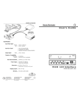
Below is an example of how an RGB 120
p
may be connected to a
computer, through an MBC buffer.
OUTPUTS
pp

Operation
Power LED: Indicates if the RGB 120p is receiving power.
Horizontal Center Control: With the H Center switch On/enabled,
the H Center Control [
] shifts the displayed image left or right.
Vertical Center Control: With the V Center switch On/enabled, the
V Center Control [
] shifts the displayed image up or down.
Level Control: Increases (clockwise) the output video level from .3 to
1 volt p-p. This is similar to a contrast control on a monitor or
projector.
Peaking Switch: Selects from three levels of peaking to compensate
for mid and high frequency signal losses due to cable length. This
is similar to the sharpness control on a monitor. The 3 switch
positions are 0 (for no peaking), 50% peaking and 100% peaking.
Select the peaking level for the sharpest image on the display.
Note: Over-peaking will distort the displayed image.
Universal Input: Using E
XTRON’S MBC input cables and buffers,
allows viewing on both the computer monitor and large-screen
projector/monitor at the same time.
MBC Power Source: Use only to power E
XTRON’S MBC buffers.
Termination Switch: 75 ohm video termination for applications with
no local monitor (Sw7, below).
Switch# Position Function
1 ON Does not allow Sync on Green
OFF Normal-Automatic Sync Output Detection
2 ON Removes serration pulses
OFF Normal-serration pulses passed through
3 ON Vertical Sync Width (500 µs)
OFF Normal-Vertical Sync Width (150 µs)
4 ON Negative Sync at all times
OFF Normal-Sync output polarity tracking
5 ON No Sync Processing (disables center controls)
OFF Normal-Sync Processing
6 ON Separate H and V Sync at all times
OFF Normal - Automatic Sync output selection
7 ON 75 ohm Input termination (no local monitor)
OFF High Z Input termination (with local monitor)
Front Panel
V CENTER
PEAK
100%
0
50%
ON
(off)
CPU
Power
MBC
Buffer
Monitor
Display
Output
Rear Panel
OUTPUTS
1
Extron • RGB 120
p
Interface • User’s Guide
Installation and Operation
Extron • RGB 120
p
Interface • User’s Guide
2
Installation and Operation
Description
The RGB 120
p
has a Video Bandwidth of 200 MHz and is
compatible with any Analog or ECL computer system with a
horizontal frequency range of 15-125 kHz. Using Extron MBC
Cables and MBC Buffers, the RGB 120
p
is compatible with VGA,
Super VGA, IBM PS/2, MAC, Sun, Silicon Graphics, XGA, XGA-2,
DEC and many others. Call Extron or refer to Extron'S Handbook
of Computer Interfacing for a complete listing.
Installation (See illustration)
1. Turn off computer and its Monitor.
2. Disconnect local Monitor cable from the computer and connect it to
the local monitor port on the MBC buffer.
3. Connect MBC interface output cable to “Analog/ECL” on the
RGB 120
p
.
4. Connect the MBC Power cable to the
RGB 120
p
.
5. Connect the MBC’s CPU cable to the
computer’s video output.
6. Apply power to the RGB 120
p
, the CPU and
monitor.
Automatic Sync Output— See Sync Output
illustration. The RGB 120
p
will automatically
output Sync on the coax cables being used,
if they are terminated with less than 1K ohm.
• Sync on Green—Cables on R, G and B only.
• Composite Sync—Cables on R, G, B, and H/HV
(not V).
• Separate H&V Sync—Cables on R, G, B, H/HV
and V.
Sync is automatically stripped from the Red,
Green and Blue channels.
-
 1
1
-
 2
2
Extron electronic Interface RGB 120p User manual
- Category
- Video switches
- Type
- User manual
Ask a question and I''ll find the answer in the document
Finding information in a document is now easier with AI
Related papers
-
Extron RGB 202 VS SL2 User manual
-
 Extron electronics RGB 118 User manual
-
Extron Extron Electronics Stereo Receiver P/N 26-177-01 User manual
-
 Extron electronics RGB 138xi User manual
-
 Extron electronics Extron Electronics Webcam RGB 304 User manual
-
Extron RGB 500 AKM User manual
-
Extron electronic PA 250 User manual
-
Extron RGB 500 User manual
-
Extron electronic Computer-Video Interface RGB 508 AKM User manual
-
 Extron electronics Network Router RGB 440 User manual
Other documents
-
 Extron electronics RGB 124 User manual
-
Extron electronics RGB 160xi User manual
-
Extron MBC User manual
-
 Extron electronics RGB 202 Rxi VTG User manual
-
 Extron electronics RGB 408 User manual
-
Extron RGB 168xi User manual
-
Extron electronics CS 1226T Plus User manual
-
 Extron electronics RGB 118 User manual
-
Extron RGB 300 User manual
-
Extron electronics RGB 109xi User manual


