Extron electronics CS 1226T Plus User manual

Category
Electrical enclosures
Type
User manual

This manual is also suitable for

CS 120P • Setup Guide
The Extron CS 120P is a plenum-rated enclosure for the Extron SpeedMount
®
Ceiling Speaker Systems. The CS 120P enclosure
can be installed in both U.S. and metric ceiling grid systems with tiles 2 feet by 2 feet (600 mm by 600 mm) or 2 feet by 4 feet
(600 mm by 1200 mm). It is UL 2043 listed for use in air handling ceiling spaces only if used in conjunction with the CS 26T or
CS 3T speakers.
This setup guide contains installation information about the CS 120P and provides procedures for installing it in suspended and
hard ceilings.
WARNING: May result in serious injury. Installation and service must be performed by authorized personnel only.
AVERTISSEMENT : Risque potentiel de blessure grave. L’installation et l’entretien doivent être effectués par le
personnel autorisé uniquement.
NOTES:
All wiring and electrical connections must conform to all applicable building codes and local ordinances.
Mounting must conform to all applicable building codes and local ordinances.
Installing the CS 120P Enclosure
The CS 120P enclosure must rst be mounted in the ceiling and wired for use with the CS 26T or CS 3T driver assembly before
the driver assembly can be installed.
The minimum ceiling thickness needed to secure the speaker is 3/8 inch (0.95 cm). The maximum ceiling thickness that can be
used is 1 and 9/32 inches (3.3 cm).
For multi-trade installations, see Division of Labor Installation on page 4.
Mounting the CS 120P in a Suspended Ceiling
1. Disconnect power — Power down all attached devices.
2. Verify the space where the CS 120P will be installed — Ensure that there is sufcient clearance above the ceiling tile
for the CS 120P to rest on top of the tile.
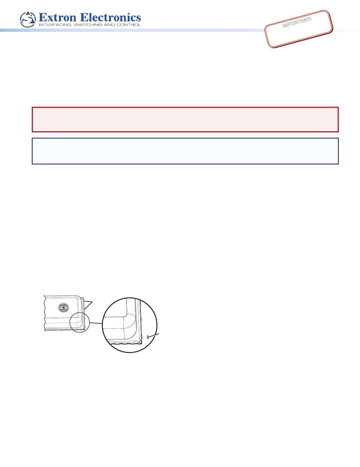
3. Configure the CS 120P for a U.S. or metric ceiling — For U.S. ceilings (2 feet by 2 feet or 2 feet by 4 feet), leave the
four tabs on the side of the CS 120P intact. For metric ceilings (600 mm by 600 mm or 600 mm by 1200 mm), cut off the
tabs.
Tabs (4)
Removable
Tabs
4. Remove the adjacent tile — To facilitate the installation process, remove the tile adjacent to the ceiling tile where the
CS 120P will be installed.
5. Cut a hole for the driver assembly. Use the provided cutout template to outline the hole to be cut in the ceiling tile as
described below.
a. Remove the ceiling tile.
b. To nd the center of the tile, use a tape measure to measure the space between two opposite corners, and mark the
half-way point.
1
IMPORTANT:
Refer to www.extron.com for the
complete user guide, installation
instructions, and specifications.
c. Position the center hole of the cutout template directly over the center of the tile that you marked in step5b.
d. Trace a circle on the ceiling tile as follows:
For installations in ceilings that are NOT fiberglass or when installing the speakers in an open back
configuration: Trace a circle around the cutout template.
NOTE: The fiberglass tile adapters are not needed and can be discarded.
For installations in a 1-inch (2.54 cm) thick fiberglass ceiling with the CS 120P:
NOTE: A set of fiberglass tile adapters is provided with both the driver assembly and the CS 120P. Only one set is
needed to install the driver assembly with the CS 120P kit in a 1-inch (2.54 cm) thick fiberglass tile. The adapter
works only with 1-inch (2.54 cm) thick fiberglass tile.
1. Place the berglass tile adapter around the outer diameter of the template that was positioned in step 5c.
2. Trace a circle around the outer diameter of the adapter.
e. Cut out the circle traced in the ceiling tile.
f. Replace the tile in the ceiling.
6. Remove the cover plate — Loosen (do not remove) the two screws on the cover plate and remove it, as shown below.
Cover Plate
7. Route the cables through the cover plate — Use one of the methods described below as appropriate.
NOTES:
The CS 120P is fully UL 2043 compliant only when it is used with a metal conduit or with plenum rated cables.
Installation of conduits and conduit adapters should conform to all applicable building codes and local ordinances.
Using a flexible conduit:
a. Route the wires through the conduit.
b. Insert the conduit into the cover plate opening
using an appropriate conduit adapter, and secure
the conduit to the plate as shown below.
c. Pull the wires out of the conduit and through the
cover plate
Using speaker wires without a conduit:
a. Secure the cable clamp adapter (included) to the cover
plate.
b. Insert the wires through the clamp and cover plate as
shown below.
c. Tighten the clamp screws.
Rear of Enclosure
Rear of Enclosure
Flexible Conduit
Flexible Conduit Adapter
Cover Plate
Secondary Cable Pass
Through Loop
Cable Clamp Adapter
Cover Plate
Secondary Cable Pass
Through Loop
NOTE: The driver assembly offers optional
two-foot V-rails and C-rings for installations
without the CS 120P (see the CS 26T Setup
Guide or the CS 3T Setup Guide for details).
2
CS 120P • Setup Guide (Continued)
8. Wire the CS 120P — Route the wires through the H-shaped opening in the
CS 120P. Be sure to leave sufcient slack, as shown on the right.
9. Replace the terminal cover plate — Reinstall the cover plate onto the
CS 120P and tighten the two screws that were loosened in step 6.
10. If the CS 120P is NOT being installed in a fiberglass ceiling tile, discard the
berglass tile adapter and go to step 11.
If the CS 120P is being installed in a 1-inch (2.54 cm) thick fiberglass ceiling,
install the fiberglass ceiling tile adapter. Attach the berglass tile adapter to the outer
side of the lip of the port hole on the CS 120P as follows:
a. Cut four strips of adhesive tape (such as duct tape)
to the appropriate size.
b. Attach each tape strip starting from the outer
side of the CS 120P metal bafe, up and over
the port ring adapter, then down to the inner
surface of the CS 120P metal bafe, as shown on
the right.
NOTE: The tape strips must lie flat against all
surfaces, with no ridges or raised edges.
11. Place the CS 120P into the ceiling grid — Place
the CS 120P over the tile grid, so that the enclosure is
safely supported on the two short edges. Ensure that
the hole in the tile is aligned with the hole in the
CS 120P.
2 feet x 4 feet (600 mm x 1200 mm) Ceiling Grid
NOTE: 2 feet x 2 feet (600 mm x 600 mm) grid mounting is the same as 2 feet x 4 feet (600 mm x 1200 mm) grid
mounting.
12. Attach safety lines and support cables — Attach all support lines as shown below.
NOTE: When placing the CS 120P in a micro tile grid without
tiles, use the secondary attachment points as hanger
suspension points.
ATTENTION:
Do not allow any slack in the support
cables.
Ne laissez aucun jeu entre les câbles de
support.
NOTE: Observe all applicable building codes
and local ordinances when installing the
speaker.
x 4 Tape
Fiberglass Tile Adapter
Secondary Support
Cables (3)
Attach cables here
and secure.
Anchor ends to suitable
solid secure points within the
permanent building structure.
3
Extron Headquarters
+800.633.9876 (Inside USA/Canada Only)
Extron USA - West Extron USA - East
+1.714.491.1500 +1.919.850.1000
+1.714.491.1517 FAX +1.919.850.1001 FAX
Extron Europe
+800.3987.6673
(Inside Europe Only)
+31.33.453.4040
+31.33.453.4050 FAX
Extron Asia
+65.6383.4400
+65.6383.4664 FAX
Extron Japan
+81.3.3511.7655
+81.3.3511.7656 FAX
Extron China
+86.21.3760.1568
+86.21.3760.1566 FAX
Extron Middle East
+971.4.299.1800
+971.4.299.1880 FAX
Extron Korea
+82.2.3444.1571
+82.2.3444.1575 FAX
Extron India
1800.3070.3777
(Inside India Only)
+91.80.3055.3777
+91.80.3055.3737 FAX
© 2014 Extron Electronics All rights reserved. All trademarks mentioned are the property of their respective owners. www.extron.com
13. See steps 5 through 11 and steps 13 through 15 in the setup guide of the driver assembly to complete
installation of the driver assembly in the CS 120P.
14. Replace the adjacent tile that was removed in step 4.
Mounting the CS 120P in a Hard Ceiling
z It is the responsibility of the installer to identify a suitable mounting location and provide the mounting hardware.
z The CS 120P must be mounted as close as possible to the upper surface of the ceiling material.
z The lip of the CS 120P should protrude into the hole cut for the speaker.
z Do not leave a gap between the CS 120P and the ceiling material.
Division of Labor Installation
z The ceiling grid must be in place before the enclosure is placed.
z If the tile will be installed later:
z Standard ceiling grid: The CS 120P can rest on the grid.
z Micro grid: The secondary attachment points should be used as the hanger suspension points (see step 12, on the
previous page).
z See Mounting the CS 120P in a Suspended Ceiling on page 1 for instructions on installing the CS 120P.
NOTE: Follow the steps below after installing the CS 120P and prior to mounting the CS 26T or CS 3T:
1. Insert the free end of the zip tie, located inside of the CS 120P (see Fig. 1), through the secondary
attachment point of the speaker (see Fig. 2A or 2B), as shown in the illustrations below.
2. Insert the free end of the zip tie into the locking connector on the opposite end of the zip tie (see Fig. 3). Leave enough slack in
the zip tie so that the speaker can be securely installed in the enclosure.
3. Continue with the remaining steps in the speaker setup guide.
Secondary
Support Line
Fig. 1
Fig. 2A
Fig. 2B
Fig. 3
Secondary
Tie off Point
Secondary
Tie off Point
Secondary
Support Line
CS 26T
CS 3T
4
68-2161-52 Rev. C
12 14
  • Page 1 1
  • Page 2 2
  • Page 3 3
  • Page 4 4

Extron electronics CS 1226T Plus User manual

Category
Electrical enclosures
Type
User manual
This manual is also suitable for

Ask a question and I''ll find the answer in the document

Finding information in a document is now easier with AI