Page is loading ...

User’s Manual
RGB 302/304
Universal Digital Interface

Extron RGB 302/304 Universal Interface • User’s Manual
Chapter One • Introduction to the RGB 302/304
RGB 302/304 Features ......................................................... 1-1
SmartSave™ .......................................................... 1-2
LCD Menu Driven Controls ..................................... 1-2
Memory Blocks and Memory Cycling...................... 1-2
Level Control (picture)............................................. 1-2
Peaking Control (sharpness) ................................... 1-3
Horizontal Shift Control (centering).......................... 1-3
Vertical Shift Control (centering).............................. 1-3
Automatic Sync Output Detection ........................... 1-3
Automatic Sync Stripping ........................................ 1-3
Keyboard Lockout ................................................... 1-3
Auto-switching Power Supply.................................. 1-3
Audio Interface ........................................................ 1-3
DIP Switch Settings ................................................ 1-4
RS-232 Control Interface for Remote Control .......... 1-4
Benefits of Windows RGB 302/304 Software .......... 1-4
Front Panel Controls .............................................................. 1-5
Menu button ............................................................ 1-5
Cursor buttons ........................................................ 1-5
Next button ............................................................. 1-5
LCD Display ........................................................... 1-5
RGB 302/304 Specifications.................................................. 1-6
Chapter Two • Installing the RGB 302/304
Easy Setup Procedure .......................................................... 2-1
Rear Panel DIP Switch Settings ............................................ 2-3
Audio Connections ................................................................ 2-3
Installation Check .................................................................. 2-4
Memory Cycling Feature ....................................................... 2-5
Preset Memory Blocks .......................................................... 2-6
Power Supply ........................................................................ 2-6
RS-232 Interface Specifications ............................................ 2-6
Application Diagrams............................................................. 2-7
Chapter Three • Front Panel Menus
RGB 302/304 Menu Sequence .............................................. 3-1
Using the Menu System ........................................................ 3-2
Default Cycle Menus ............................................................. 3-3
Default Cycle Hot Keys........................................... 3-4
Language Menu ...................................................... 3-4
Keyboard Lock/Unlock Menu .................................. 3-5
Digital Display Sync Processing ............................. 3-5
Image Controls Menus .......................................................... 3-6
Horizontal Shift Menu .............................................. 3-6
Vertical Shift Menu .................................................. 3-6
Level Control Menu ................................................. 3-7
Peaking Control Menu ............................................. 3-7
Page i
Contents

Extron RGB 302/304 Universal Interface • User’s Manual
Sync Controls Menus ............................................................ 3-8
Sync Output Menu .................................................. 3-8
Horizontal Polarity Menu ......................................... 3-9
Vertical Polarity Menu ............................................. 3-9
Option Controls Menus........................................................ 3-10
LCD Backlite Menu ............................................... 3-10
Memory Cycling Menu .......................................... 3-10
System Reset Menu ............................................. 3-10
Confirm Reset Menu ............................................. 3-11
Exit Menu ............................................................................ 3-11
Default Settings on Power Up .............................................. 3-11
Default Settings on System Reset ....................................... 3-11
Chapter Four • Using the Windows® Control Program
Installing Windows® Control Software ................................... 4-1
Normal Windows Control Panel ............................................. 4-2
RGB 302/304 Help ................................................................ 4-3
Appendix A • Programmer’s Guide
Remote Control Port (RS-232) .............................................. A-1
Host-to-RGB 302/304 Instructions ........................................ A-2
Simple Commands ................................................................ A-3
Error Codes .......................................................................... A-4
RGB 302/304-Initiated Messages .......................................... A-5
RGB 302/304 User’s Manual
68-354-01
First Edition
89-03
Written and printed in the USA
Page ii
Contents

Extron RGB 302/304 Universal Interface • User’s Manual Page iii
Legend
Legend of Icons
The following icons may be used in this manual:
______ Important information – for example, an action or a
step that must be done before proceeding.
______ A Warning – possible dangerous voltage present.
______ A Warning – possible damage could occur.
___ A Note, a Hint, or a Tip that may be helpful.
____ Possible Electrostatic Discharge (ESD) damage
could result from touching electronic components.
_____ Indicates word definitions. Additional information may
be referenced in another section, or in another
document.

Extron RGB 302/304 Universal Interface • User’s Manual
Notes
Page iv
____

Extron RGB 302/304 Universal Interface • User’s Manual
1
Chapter One
Introduction to the RGB 302/304
SmartSave™
LCD Menu Driven Controls
Memory Blocks and Memory Cycling
Image Display Controls
Automatic Sync Output Detection
Keyboard Lockout
RS-232 Control Interface
Front Panel Controls
Specifications
RGB 302/304 Universal Digital Interface
User’s manual

Extron RGB 302/304 Universal Interface • User’s Manual
The Extron RGB 302/304 is a digitally controlled
Universal Analog/ECL Computer-Video Interface. It
can connect most computers to a video presentation
device, such as a large screen projector or data
monitor. The RGB 302/304’s SmartSave™ feature
automatically selects sync settings and other
parameters for a quick and easy setup.
Among the RGB 302/304 features are RGB input/
output connectors, an MBC power jack, audio input/
output connectors, an RS-232 connector, and rear
panel DIP switches.
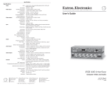
The RGB 304 is identical in performance and features
as the RGB 302 with the exception being that, unlike
the RGB 302, the RGB 304 has its 9-pin Analog/ECL
input, Audio input, and MBC power jack located on the
front panel of the unit, as shown below. This difference
allows the RGB 304 to be installed in situations where
front panel access to such connectors may be
necessary, such as the mounting of the unit in a rack
mount environment.
RGB 302/304 Features
The RGB 302/304 features allow video output to be
controlled in several ways:
• Automatic sync output detection and setup for quick
installation
• Custom setup and adjustments made from the Front
Panel (shown below)
• RGB 302/304 Windows® software, through an RS-232
interface
• User-written programs through the RS-232 port
Page 1-1
Chapter 1 • Introduction to the RGB 302/304
MENU NEXT
RGB 302
MENU NEXT
RGB 304
MBC
POWER
ANALOG/ECL
AUDIO IN
INPUT

Extron RGB 302/304 Universal Interface • User’s Manual
SmartSave
™
This unique feature greatly simplifies the video
configuration setup of the RGB 302/304. The
RGB 302/304 comes preset with various video
configurations to match most computer video
requirements. The proper configuration is
automatically selected and implemented for the user.
In addition, the RGB 302/304 will automatically save
any user modifications to the video configuration and
will recall the correct configuration without need for
user intervention.
LCD Menu Driven Controls
The RGB 302/304 does not have front panel “knobs”
or “switches” to control its operation. Instead, the
“controls” are displayed and adjusted using the Front
Panel LCD display and the six front panel buttons.
The Front Panel display can be used in any of four
languages: English, French, Spanish and German.
The display serves two purposes:
1. The RGB 302/304 automatically detects and
displays vital troubleshooting information, such as
the horizontal and vertical scan frequencies.
2. The user can step through and display any of the
controls or features in the interface.
___ Chapter 3 has details on using the Front Panel.
Memory Blocks and Memory Cycling
There are 15 preset memory blocks which store video
format information, such as video, sync and control
settings. Each block is preloaded by Extron and
defines one video configuration (e.g. VESA3, MAC16",
etc.). These preset memory blocks define most video
requirements. In addition, there are 25 user-definable
memory blocks available.
The RGB 302/304 automatically cycles through
(Memory Cycling) the user-defined memory blocks
and loads the video format that most closely matches
the computer’s video output. Should a match not be
found, the 15 preset memory blocks are searched
next (refer to
the section “Memory Cycling Feature”
in
Chapter 2).
Level Control (picture)
This feature is similar to the brightness control on a
data monitor and is used to adjust the intensity of the
video level on the projector/monitor screen by using
the cursor keys. There are 255 levels for this control.
Page 1-2
Chapter 1 • Introduction to the RGB 302/304

Extron RGB 302/304 Universal Interface • User’s Manual
Peaking Control (sharpness)
This control is similar to the sharpness control on a
data monitor. It is also used to compensate for long
cable runs. There are eight Peaking levels which are
selected by using the cursor keys.
Horizontal Shift Control (centering)
This feature shifts the displayed image to the left or
right on the projector/monitor screen by using the
cursor keys. There are 255 positions for this control.
Vertical Shift Control (centering)
This feature shifts the displayed image up or down on
the projector/monitor screen by using the cursor keys.
There are 255 positions for this control.
Automatic Sync Output Detection
The RGB 302/304 automatically detects which cables
are connected and sends either Sync On Green,
Composite Sync or Separate Horizontal and Vertical
sync signals to the correct output cables. This
function can be overridden through menu controls.
Automatic Sync Stripping
The RGB 302/304 automatically strips all incoming
sync from the red, green, and blue channels for clean,
crisp signal processing. Sync may be recombined with
the green channel if necessary.
Keyboard Lockout
The RGB 302/304 features a Keyboard Lockout
function which allows the user to “lock out” the front
panel controls by using “hot keys”. This feature
disables front panel operation after setup.
Auto-switching Power Supply
The RGB 302/304 is equipped with an internal auto-
switching power supply that operates from any input
voltage in the 100 to 240 VAC, 50/60 Hz range. No
equipment changes are necessary.
Audio Interface
The RGB 302/304 includes a PC/computer audio (600
ohm) to line-level audio (balanced) converter. For
computers which have a sound card, the audio
interface will process the audio signal along with the
video (audio follow). The audio output can be
connected to an external stereo system.
Page 1-3
Chapter 1 • Introduction to the RGB 302/304

Extron RGB 302/304 Universal Interface • User’s Manual Page 1-4
Chapter 1 • Introduction to the RGB 302/304
DIP Switch Settings
The RGB 302/304 includes a rear panel DIP switch
bank which will activate Digital Display Sync
Processing, remove/pass serration pulses, and set 75
Ohm/high impedance video input termination.
RS-232 Control Interface for Remote Control
The RGB 302/304 has a built-in RS-232 interface to
allow the unit to be controlled remotely in either of two
ways:
1. Use the Windows® RGB 302/304 Control Panel
software provided by Extron (see next section).
2. The user may write software to control the RGB 302/
304 from a PC or control system. See the
Programmer’s Guide in Appendix A.
The RS-232 protocol is fixed at 9600 baud, no parity, 8
data bits and 1 stop bit.
Benefits of Windows® RGB 302/304 Software
Using the Windows® software provided with the
RGB 302/304 adds several advantages over Front
Panel operation.
• All of the controls are quick and easy to use with
the on-screen control panel.
• Application setups can be stored as disk files,
therefore, an unlimited number of setups can be
stored and reloaded from the PC’s hard drive or
floppy disk.
Refer to Chapter 4 for details on using this software.

Extron RGB 302/304 Universal Interface • User’s ManualPage 1-5
Front Panel Controls
The Front Panel buttons (as shown below) have many
functions, depending on which menu is accessed at
any particular time. For example, the user can display
and adjust controls to modify the video display. The
specific functions for these buttons are described
below.
The LCD panel cycles through 3 default menus when
the RGB 302/304 is first powered on. Refer to Chapter
3 for instructions on using the RGB 302/304 menus.
___ There is a built-in time-out function which will return to
the default menu cycle if no buttons are pressed for
approximately 8 seconds. By default, any changes
which were made will be automatically saved upon the
time-out.
Menu button
The Menu button is used to select and step through
the four different menu classes (to be explained in
Chapter 3).
Next button
The Next button is used to advance to the next
submenu of a menu class or to return to the beginning
of the menu class (see the menu flowchart on page 3-1).
Cursor buttons
The cursor buttons are typically used to step through
the menu options before making a choice. These
options could be alpha characters or numeric settings.
The user may also want to change the value of the
current setting (i.e., increase or decrease level, shift,
peaking, etc.). These buttons also serve as
convenient “hot keys” to various functions.
LCD Display
Besides displaying the menus, the LCD display
provides some helpful information, such as which
buttons to use when making choices.
MENU NEXT
RGB 302
MENU NEXT
RGB 304
MBC
POWER
ANALOG/ECL
AUDIO IN
INPUT
MENU
NEXT
Chapter 1 • Introduction to the RGB 302/304

Extron RGB 302/304 Universal Interface • User’s Manual
RGB 302/304 Specifications
Part Number .. 60-243-01 (RGB 302)
.. 60-244-01 (RGB 304)
User’s Manual ..68-354-01
Dimensions ..8.75" W x 9.5" D x 1.75" H
Shipping Weight ..5 lbs
Input Power ..100 - 240 VAC, 50/60 Hz,
auto-switchable, internal
Power Consumption ..17 watts
Operating Temperature ..0° C to 50° C
Control Baud Rate .. 9600 baud
Input Signal:
Video ..2V p-p max
Video Impedance ..75 Ω terminated, 7.5 kΩ untermin.
Sync ..Separate H & V Sync TTL (±)
..Composite H & V TTL (±)
..Sync on Green (-).3V
..Sync on Red, Green & Blue (-).3V
Sync Impedance ..10 kΩ
Audio .. Connector: 3.5 mm jack
Audio Impedance .. High Z
Output Signal:
Video .. .35V to 1V p-p with .7V applied
Video Impedance .. 75 Ω
Sync ..Sync on Green (-)
..Composite Sync (-)
..Separate H & V (±)
Sync Impedance ..75 kΩ
Audio .. Connector: 3.5 mm jack
Audio Impedance .. 600 Ω
Frequency Compatability:
Horizontal ..15 - 125 kHz (automatically)
Vertical ..30 - 170 Hz (automatically)
RGB Video Bandwidth ..220 MHz (2 ns rise time)
LCD Scan Rate Range:
Horizontal ..15 - 150 kHz
Vertical ..30 - 170 Hz
LCD Menu (Front Panel): .. Back-lit alphanumeric display
(English, German, Spanish or
French)
Warranty ..Two years, parts and labor
Chapter 1 • Introduction to the RGB 302/304
Page 1-6

Extron RGB 302/304 Universal Interface • User’s Manual
Chapter 1 • Introduction to the RGB 302/304
Page 1-7
____

Extron RGB 302/304 Universal Interface • User’s Manual
2
Chapter Two
Installing the RGB 302/304
Easy Setup Procedure
DIP Switch Settings
Audio Connections
Installation Check
Memory Cycling Feature
RS-232 Specifications
RGB 302/304 Universal Digital Interface
User’s manual

Extron RGB 302/304 Universal Interface • User’s ManualPage 2-1
Chapter 2 • Installing the RGB 302/304
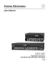
____ The diagrams above show the front and rear panels of
the RGB 302 (top pair) and RGB 304 (bottom pair).
Easy Setup Procedure
These easy-to-follow steps describe the general setup
of the RGB 302/304. Refer to the example
Application
Diagrams
at the end of this chapter.
1. Turn the computer and monitor power Off.
Do not connect the RGB 302/304 power cable yet
(there is no power switch).
2. Disconnect and remove the computer’s local monitor
video cable from the computer video port.
3. Connect BNC output cables from the RGB 302/304
to the data monitor/projector — all BNC outputs are
RGB analog. The BNC connectors are marked R, B,
G, H/V and V. They may be connected in any of
three ways:
• Red, Green/sync and Blue, for RGB with sync on
Green. (3-cable hookup)
• Red, Green, Blue and H/HV, for RGB with Composite
sync signals. (4-cable hookup)
• Red, Green, Blue, H/HV and V, for RGB with separate
Horizontal and Vertical sync signals. (5-cable hookup)
MENU NEXT
RGB 304
OUTPUT
R
50/60 Hz
100-240V 0.5A
G B H/HV V
LR
OUT
MBC
POWER
RS-232
ANALOG/ECL
AUDIO IN
AUDIO
DDSP
SER REM
75 OHM
INPUT
MENU NEXT
RGB 302
OUTPUT
R
50/60 Hz
100-240V 0.5A
G B H/HV V
LR
OUT IN
MBC
POWER
RS-232
ANALOG/ECL
INPUT
AUDIO
DDSP
SER REM
75 OHM

Extron RGB 302/304 Universal Interface • User’s Manual Page 2-2
Chapter 2 • Installing the RGB 302/304
____ The Extron RGB 302/304 automatically detects which
cables are connected and sends sync signals to the
correct output.
4. Connect the Analog/ECL MBC video cable from the
computer (Power PC, PC, Mac, or workstation) to
the Analog/ECL Input connector on the RGB 302/
304 and to the local monitor. See note below.
____ If a Laptop Breakout Cable (LBC) is being used, set
DIP Switch 3 to Off. Refer to “Rear Panel DIP Switch
Settings” in the next section.
4a. MBC Power Connector — If an MBC buffer is
being used, plug the phone jack into the MBC
power female connector of the RGB 302/304.
5. RS-232 Control (optional) — If using a PC or other
system to control the RGB 302/304, connect the
cable here (pinouts and interface specifications are
given under the section
“Installation Check”
later in
this chapter).
6. Turn power On at the local computer monitor. Next,
turn power On at the computer supplying the video
input — (Power PC, PC, Mac or workstation).
6a. Turn power On at the data monitor/projector.
6b. Connect power to the RGB 302/304.
7. Observe that the RGB 302/304 LCD display lights up
and cycles through the three default menus (below).
7a. The ID or Title Menu - Displays the name of
the unit. To change this display, see
“Editing
the ID Screen”
in Chapter 3.
7b. The Scan Rate Menu - From the monitor
breakout cable, the RGB 302/304 detects
the scan rate frequencies and displays
them. The scan rate display on the left is an
example.
7c. The Sync Output-Memory Cycling Menu -
As an example, if the RGB 302/304 has
detected an output with sync on Green and
Memory Cycling is turned On, the first line
will display “Sync Out: Green” and the
second line will display “Mem Cycling: On” .
Refer to the
“Memory Cycling Feature”
section in this chapter for a detailed
explanation of Memory Cycling.
ANALOG/ECL
INPUT
RS-232

Extron RGB 302/304 Universal Interface • User’s ManualPage 2-3
____ Memory Cycling can be On or Off. Sync Output can be
Green, Comp (Composite), H&V (Separate Horizontal
& Vertical), or Auto (Automatic).
Automatic Sync
means the RGB 302/304 detects which output
connectors are currently active and will set and display
the output sync as either Green, RGBS or RGBHV,
depending on the connections.
Rear Panel DIP Switch Settings
The RGB 302/304 has three DIP switch settings:
Switch 1: On = Digital Display Sync Processing
Off = Processed sync (normal)
Switch 2: On = Remove serration pulses
Off = Pass serration pulses (normal)
Switch 3: On = 75-Ohm input termination
Off = High impedance input termination
Audio Connections
The RGB 302/304 provides audio interfacing to the
audio output which is connected to the user’s audio
equipment. The user supplies the audio cables.
On the RGB 302, the audio input and output are both
located on the rear panel, as shown in the diagram to
the left.
The RGB 304 has the audio output
located on the rear panel, but the
audio input is situated on the front
panel, as shown to the right.
The audio interface is a PC/computer audio (600 Ω) to
line-level audio (balanced) converter. If the computer
has a sound card, the RGB 302/304 will distribute the
audio with the video (audio follow).
Although the input and output audio connectors are
physically the same, they are used differently. See the
illustration and the following descriptions for the
correct wiring of audio inputs and outputs.
Audio Input — Connect the stereo audio sources to
Audio In. Input cables should be wired as follows:
• Stereo left to Tip (+) contact
• Stereo right to Ring (-) contact
• Both commons to Sleeve (Gnd) contact
Chapter 2 • Installing the RGB 302/304
DDSP
SER REM
75 OHM
On
Off
123
LR
OUT IN
AUDIO
RGB 302
AUDIO IN
LR
OUT
AUDIO
RGB 304

Extron RGB 302/304 Universal Interface • User’s Manual Page 2-4
Chapter 2 • Installing the RGB 302/304
Audio Output (Left and Right) — There is one audio
output using separate connectors for left and right
channels. Connect the left and right output jacks to the
inputs of an external audio system. The 3-contact
outputs can be wired for balanced or unbalanced
audio.
• For unbalanced audio, use Tip (+) and Sleeve (Gnd)
• For balanced audio, use Tip (+) and Ring (-)
____ Observe polarity when making connections to keep left
and right channels in phase.
Installation Check
To verify that the installation is complete, do the
following:
1. Check that the LCD default menus show the correct
information (as previously described in Step 7). Use
the menus as a troubleshooting aid.
If no video input was detected, no memory
block was loaded, and the display will show
zeroes.
The scan rate menu may be used for
troubleshooting as follows:
• The timing for the RGB 302/304 is derived from
the vertical sync signal. If the vertical sync signal
is not present, both the vertical and horizontal
frequencies will be zeroes, even if there is a
horizontal signal present.
• If a vertical sync signal is detected and the
horizontal sync is not detected, the vertical
frequency is displayed, but the horizontal
frequency is zeroes.
2. Recheck the previous Easy Setup Procedure steps
for correct cable connections, etc.

Extron RGB 302/304 Universal Interface • User’s Manual
Chapter 2 • Installing the RGB 302/304
Memory Cycling Feature
The RGB 302/304 is preset at the factory with fifteen
video formats which are stored in memory blocks.
These memory blocks contain video formats which
will match most computers. There are also 25
additional empty memory blocks which are user-
defined.
When a video input is connected and the RGB 302/
304 is powered On, the 25 user-defined memory
blocks are scanned (cycled) sequentially for a
configuration which matches the computer’s video
input. If a match is found, that format’s stored settings
are implemented. If a match is not found, the 15 preset
video formats are scanned next. If a match is found,
that format and any adjustments to the image are
automatically saved to a user-defined memory block (if
Memory Cycling is set On). If a match is not found
among the preset formats, a new video format will be
created and stored (see note below) as a user-defined
memory block.
The 25 user-defined memory blocks are filled
sequentially (1 to 25). If the last empty memory block
(#25) has already been filled and a new video format is
added, memory block #1 will be overwritten. Additional
new formats will sequentially overwrite memory blocks
#2, #3, #4, etc., and start over again at memory block
#1, #2, #3, etc.
The 15 preset memory blocks are permanently stored,
while the 25 user-defined memory blocks can only be
cleared by resetting the RGB 302/304 (refer to
System Reset Menu in the
“Option Controls Menus”
section of Chapter 3). Powering Off the RGB 302/304
will not delete any of the memory blocks.
____ If Memory Cycling is disabled (set Off), any changes to
a video configuration will not be stored in a memory
block and no new memory blocks will be saved. Refer
to Memory Cycling Menu in the “Option Controls
Menus” section of Chapter 3.
Page 2-5

Extron RGB 302/304 Universal Interface • User’s Manual Page 2-6
Chapter 2 • Installing the RGB 302/304
Preset Memory Blocks
The Memory Cycling feature supports 25 user-defined
memory blocks for storing video configurations and 15
permanently defined memory blocks. The 15 preset
memory block video configurations are listed below.
No. Format Horizontal Frequency [kHz] Vertical Frequency [Hz]
1 VGA1 31.5 70
2 VGA2 31.5 70
3 VGA3 31.5 60
4 VESA1 35.2 56
5 VESA2 37.9 72
6 VESA3 48.4 60
7 VESA4 56.4 70
8 VESA5 38.0 60
9 VESA6 48.0 72
10 Mac 13" 35.0 67
11 Mac 16" 49.7 75
12 Mac 21" 68.7 75
13 Sun1 71.7 76
14 Sun2 81.0 76
15 SGI 63.9 60
Power Supply
The RGB 302/304 is equipped with an internal auto-
switching power supply that operates from any input
voltage in the 100 to 240 VAC, 50/60 Hz range. No
equipment changes are necessary.
RS-232 Interface Specifications
9600 baud, no parity, 8 data bits and 1 stop bit.
RS-232 Connector Pins are assigned as follows:
Pin Signal Pin Signal Pin Signal
1 — 4 — 7 —
2 Transmit 5 Ground 8 —
3 Receive 6 — 9 —
RS-232
/