Page is loading ...

MAN075 Rev 1/11/ 07
Console Switch
Installation and Operation Manual
SERIMUX
®
Series
NETWORK
TECHNOLOGIES
INCORPORATED
Tel:330-562-7070
Fax:330-562-1999
1275 Danner Dr
Aurora, OH 44202
www.networktechinc.com
NTI
R

i MAN075 Rev 1/11/07
TRADEMARK
SERIMUX is a registered trademark of Network Technologies Inc in the U.S. and other countries.
COPYRIGHT
Copyright © 2004-2007 by Network Technologies Inc. All rights reserved. No part of this publication may be reproduced, stored
in a retrieval system, or transmitted, in any form or by any means, electronic, mechanical, photocopying, recording, or otherwise,
without the prior written consent of Network Technologies Inc, 1275 Danner Drive, Aurora, Ohio 44202.
CHANGES
The material in this guide is for information only and is subject to change without notice. Network Technologies Inc reserves the
right to make changes in the product design without reservation and without notification to its users.

ii MAN075 Rev 1/11/07
TABLE OF CONTENTS
Introduction......................................................................................................................................................................1
Materials..........................................................................................................................................................................1
Serial Interface Specifications.........................................................................................................................................2
Definitions........................................................................................................................................................................2
Features and Functions...................................................................................................................................................3
Installation .......................................................................................................................................................................4
Rack mounting Instructions .........................................................................................................................................4
Cable Connections ......................................................................................................................................................4
Initial Startup ...................................................................................................................................................................5
SERIMUX Quick Start..................................................................................................................................................5
Using the SERIMUX Console Switch..............................................................................................................................6
Serial Control............................................................................................................................................................6
Administrator Controls.....................................................................................................................................................7
Login as the administrator ........................................................................................................................................7
Port List........................................................................................................................................................................8
Port Settings ................................................................................................................................................................9
Port serial settings ..................................................................................................................................................11
Baud rate.............................................................................................................................................................11
Data bit ................................................................................................................................................................11
Stop Bit................................................................................................................................................................11
Parity....................................................................................................................................................................11
Flow Control.........................................................................................................................................................11
Xon or Xoff Characters........................................................................................................................................12
DTR line behavior................................................................................................................................................12
Inter-character delay............................................................................................................................................12
Line-break receive or transmit.............................................................................................................................12
Copy Port Serial Settings ....................................................................................................................................13
Display serial settings for different port number..................................................................................................13
Modem settings.......................................................................................................................................................13
Port data buffer.......................................................................................................................................................14
User List.....................................................................................................................................................................15
User Settings.............................................................................................................................................................16
Port access.............................................................................................................................................................17
Copy User Settings.................................................................................................................................................17
Advanced Settings.....................................................................................................................................................18
Change administrator password.............................................................................................................................18
Firmware.................................................................................................................................................................19
Load new firmware..............................................................................................................................................19
Save current firmware .........................................................................................................................................19
User Controls ................................................................................................................................................................20
User "Accessible host list" screen.............................................................................................................................20
User main menu ........................................................................................................................................................21
Port List screen..........................................................................................................................................................22
User Terse mode.......................................................................................................................................................23
Terse mode commands..........................................................................................................................................23
Keypad Control..............................................................................................................................................................24
Functions of the Keypad.........................................................................................................................................24
Initialize SERIMUX Console Switch to default settings.............................................................................................27
Using the Keypad....................................................................................................................................................27
Using The "RESET" Button ....................................................................................................................................28
Firmware Upgrade.........................................................................................................................................................28
Interconnection Cable Wiring Method...........................................................................................................................30
Troubleshooting.............................................................................................................................................................30
Specifications ................................................................................................................................................................34
Index..............................................................................................................................................................................34
Warranty Information.....................................................................................................................................................34

iii MAN075 Rev 1/11/07
TABLE OF FIGURES
Figure 1- Mount switch to a rack........................................................................................................................................................4
Figure 2- Connect terminals and devices to SERIMUX Console Switch............................................................................................4
Figure 3- Startup- Accessible host list ...............................................................................................................................................5
Figure 4- Administrator main menu....................................................................................................................................................7
Figure 5- The Port list displays the status of all ports ........................................................................................................................8
Figure 6- The Port settings menu ......................................................................................................................................................9
Figure 7- Control Codes for in-band disconnect sequence..............................................................................................................10
Figure 8- Port serial settings menu..................................................................................................................................................11
Figure 9- Modem settings menu......................................................................................................................................................13
Figure 10- Port data buffer...............................................................................................................................................................14
Figure 11- User List .........................................................................................................................................................................15
Figure 12- User settings menu.........................................................................................................................................................16
Figure 13- Port access list for User 01.............................................................................................................................................17
Figure 14- Administrator's Advanced settings menu........................................................................................................................18
Figure 15- Firmware menu...............................................................................................................................................................19
Figure 16- The SERIMUX is waiting to save its firmware.................................................................................................................20
Figure 17- A user with limited host port access ...............................................................................................................................21
Figure 18- User main menu.............................................................................................................................................................21
Figure 19- A limited user accessible Port list...................................................................................................................................22
Figure 20- User port in Terse mode.................................................................................................................................................23
Figure 21- Keypad and LEDs...........................................................................................................................................................24
Figure 22- Location of RESET button..............................................................................................................................................28
Figure 23- Location of write-protection jumper JP3 .........................................................................................................................28
Figure 23- New firmware upload window.........................................................................................................................................29
Figure 24- SERIMUX waiting for firmware file to be sent.................................................................................................................29
Figure 25- View looking into RJ45 female........................................................................................................................................30
APPENDICES
Appendix A - SERIMUX Port Characteristics...................................................................................................................................31
Appendix B - SERIMUX User and Administrator Characteristics.....................................................................................................31
Appendix C- Cable Adapters ...........................................................................................................................................................32

NTI SERIMUX SERIES CONSOLE SWITCH
1
INTRODUCTION
The NTI SERIMUX Console Switch is a serial port router that allows links (or connections) between multiple pairs of RS-232
asynchronous serial ports. The main purpose of the switch is to enable users to manage several serial devices from local or
remote locations (using external modems). Devices include routers, DSU's, servers, switches or any other equipment allowing
serial operation using RS232 interface. Users can work locally using a VT100 or ANSI serial console or a CPU with a terminal
program (i.e. HyperTerminal)) or from remote locations.
Each SERIMUX port has to be configured for serial communication (baud rate, parity, etc) within the specifications of the attached
serial device, but the configurations of the two devices linked by the SERIMUX do not need to match. Various parameters
(communication speed, hardware and/or software flow control, timeout, etc) can be selected for each SERIMUX port. Devices
may be either locally connected or connected through attached modems.
Each SERIMUX port can be configured as either a host or user port. Serial hosts (such as servers, switches etc.) are connected to
host ports, while serial user devices (such as a terminal or serial console) are connected to user ports.
The SERIMUX Console Switch supports two operator levels: user and administrator. Users login at user ports and connect to
serial devices attached at host ports. The administrator (logged in at any user port) and users with administrative privileges can
see and/or modify various port or user parameters.
MATERIALS
Materials Supplied with this kit:
• SERIMUX Console Switch
• 100-240VAC, 50 or 60Hz / 9VDC 1.5A AC Adapter
• CD with a pdf file of this manual
• 10-32 x 3/4" pan head screws and 10-32 cagenuts (server cabinet mounting hardware)
Also supplied with units having RJ45 connectors:
• DB25F-RJ45F Console Adapter RJ45-DB25 Female
• DB25M-RJ45F-T Console Adapter RJ45-DB25 Male
• DB25M-RJ45F-C Modem Adapter RJ45- DB25 Male
• DB9F-RJ45F Serial Adapter RJ45-DB9 Female
Note: The power socket on the SERIMUX is marked "12VDC". The SERIMUX operating range is 9-12VDC.
Materials Required but not supplied:
Serial cable with at least one RJ45 male end for connection to the Console Switch from each device to be connected. See
Interconnection Cable Wiring Method on page 30 for cable pinout.

NTI SERIMUX SERIES CONSOLE SWITCH
2
SERIAL INTERFACE SPECIFICATIONS
• Number of ports: 9, 17, 25 or 33 RS232 ports;
• Connectors: RJ45 male
• Data: asynchronous, 5, 6, 7, or 8 bits per character,
• Parity: even, odd, or none
• Stop Bits: 1, 1 , 2, or 2 bits
• Flow Control: Xon/Xoff, RTS/CTS, Both, or None
• Baud Rate: 50 bps to 128,000 bps
DEFINITIONS
device equipment that can transmit and/or receive data using RS232 interface
inactivity when a port is not receiving data from the device connected to it
terminal program a terminal emulation program- computer program that communicates via RS232 interface
(i.e. HyperTerminal)
"dumb" terminal Serial terminal device or CPU terminal program that emulates a serial terminal
timeout time period of inactivity after which a port will be disconnected (the inter-port connection will be broken)
Baud rate serial device or port receiver and transmitter speed; measured in "bps" (bits per second)
Flow control a method to temporarily stop and restart serial data transfer (flow). It can be
- Hardware (out-band)- usually using the RTS and CTS physical handshaking signals;
- Software (in-band)- using special characters, usually named Xon and Xoff, inserted
in data being transferred;
- Both
Disconnect sequence 1 or 3 char sequence inserted in the serial data flow, to disconnect the user from the
attached serial device and to return to the initial user menu.
[CR] "Carriage Return" character, ASCII code 13
[LF] "Line Feed" character, ASCII code 10
[FF] "Form Feed" character, ASCII code 09
+ (i.e. [ Shift ] + [ < ] ) press the keys simultaneously
- (i.e. [ P ] - [ 0 ] ) press the P and 0 keys consecutively

NTI SERIMUX SERIES CONSOLE SWITCH
3
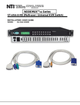
FEATURES AND FUNCTIONS
1. PWR LED- LED will illuminate to indicate the SERIMUX is ON
2. Port LEDs- LEDs will illuminate to indicate active administrator port and data traffic; also used to indicate port or user number
when entering commands from the keypad.
3. Command LEDs- LEDs will illuminate to indicate functions being performed
4. Keypad- for manual control of switch functions
5. Port connectors- RJ45 female serial connectors- for connecting serial cables from Terminals or CPUs
6. Console Port- RJ45 female serial connector- for connecting serial cable from a terminal console
7. Reset button- to manually reset SERIMUX firmware to factory default settings
8. Power Switch- for turning the SERIMUX ON or OFF
9. 12VDC 2A- connection jack for the AC adapter (acceptable operating voltage is 9-12VDC)
PWR
1
0246
35
8
7
10
9
12
11
14
13
16
15 Port Admin User Discon
ESC
ADMIN USER
PORT 6
12345ENTER
DISCON7890
12VDC
2A
-
+
NTI
NETWORK
TECHNOLOGIES
INCO RPORATE D
Tel :330-5 62-70701275 Danner Dr
Aurora, OH 44202
www.nti1.com
RESET
CONSOLE
NTI
R
Network Technologies Inc
Rear View of SERIMUX
Front View of SERIMUX
2 3
41
5 798
9101112
13
141516
123
4
5678
6
SERIMUX
R

NTI SERIMUX SERIES CONSOLE SWITCH
4
12VDC
2A
-
+
NTI
NETWORK
TECHNOLOGIES
INCORPORATED
Tel :330-5 62-70701275 Danner Dr
Aurora, OH 44202 www.nti1.com
RESET
CONSOLE
Rear View of SERIMUX
9101112
13
141516
12345678
USER DEVICE
(VT100, ANSI serial console,
PC w/ Terminal Emulation
Program)
SERVER
IC CHIP
PROGRAMMER
CNC
PUNCHPRESS
RJ45 Male Connector
INSTALLATION
Rack mounting Instructions
The NTI switch was designed to be directly mounted to a rack and includes a mounting flange to make attachment easy.
Install 4 cage nuts (supplied) to the rack in locations that line up with the holes (or slots) in the mounting flange on the NTI switch.
Then secure the NTI switch to the rack using four #10-32 screws (supplied). Be sure to tighten all mounting screws securely.
Do not block power supply vents in the NTI switch chassis (if provided) . Be sure to enable adequate airflow in front of and
behind the NTI switch.
Attach all cables securely to the switch and where necessary supply adequate means of strain relief for cables.
Figure 1- Mount switch to a rack
Cable Connections
1. Connect a serial device to the port labeled "CONSOLE" on the SERIMUX using a serial cable with an RJ45 male connector
(see cable specification on page 30). This will be the default administrator device. (Fig. 1)
2. Connect each additional serial device or host to be connected by the SERIMUX to any remaining port (1-16/24/32) using a
DTE or DCE type serial cable. It may be necessary to add one of the cable adapters (supplied) detailed in Appendix C (page
31) between the device port on the serial device or host and the RJ45 connector.
3. Follow the "Initial Startup" instructions that follow.
Figure 2- Connect terminals and devices to SERIMUX Console Switch
Cage Nuts
Rack Screws
Rack
(supplied)
10-32
(supplied)
Note: There are two types of
serial devices, data
communication equipment
(DCE)(i.e. modem) and data
terminal equipment (DTE) (i.e.
CPU), each having different
connector pin assignments.
The cable adapters (see
Appendix C on page 32) make
the proper connections.

NTI SERIMUX SERIES CONSOLE SWITCH
5
INITIAL STARTUP
SERIMUX Quick Start
1. Make sure the SERIMUX is turned OFF.
2. Using the serial device connected to the port labeled "CONSOLE", start the terminal program (e.g. Windows HyperTerminal)
and configure it as follows:
• direct connection (using the appropriate CPU local serial Com port)
• 9600 bps
• 8 bits
• no parity
• 1 stop bit
• no flow control
• ANSI or VT100 terminal mode.
Within the SERIMUX firmware, the "CONSOLE" port is identified as Port 0. For consistency, when Port 0 is
mentioned within this manual, it refers to the terminal connected at "CONSOLE".
3. Power ON the SERIMUX. Wait 2 seconds.
4. Press [ Enter ] on the keyboard and wait 3 seconds to be recognized as the default SERIMUX user. The "Accessible host list"
for "User01", logged in at "Port00" will be displayed (see Fig 3). By default, all ports are configured as Host ports and all are
accessible.
NOTE: If the user menu does not display re-initialize the SERIMUX following the "Initialize SERIMUX Console Switch to
default settings" instructions on page 27.
5. To connect to an attached CPU, enter the number of the port the CPU is connected to and press [Enter].
Figure 3- Startup- Accessible host list

NTI SERIMUX SERIES CONSOLE SWITCH
6
USING THE SERIMUX CONSOLE SWITCH
The SERIMUX Console Switch is controlled using
• Serial Control- from a "dumb" terminal- locally connected
- through an external modem from a remote location
• Keypad Control (reduced set of commands)
Serial Control
The SERIMUX Console Switch can be easily configured using serial communications with a keyboard-controlled menu to modify
various parameters and options for each port to be connected to a device. The administrator menu can be accessed by the
administrator for full feature control, or the user menu, by any user, for more restricted control of port connections.
Keypad Control
The keypad has direct control over basic SERIMUX functions. The keypad can be used to make changes to port connections
regardless of any menu control taking place. Command LEDs on the front panel of the SERIMUX Console Switch indicate the
status of the switch and what function is being performed. For more on Keypad Control, see page 24.
Serial Control
Using serial control, the SERIMUX supports 2 operator levels, administrator and user, each with separate password protection for
security.
• The administrator logs in using an administrator password
administrator name : ADMINISTRATOR or ROOT (all capital letters)
administrator password : NTI (default)
• Users login using a password set by the administrator
FYI: Users may be granted administrative access rights by the administrator.
The administrator and any user with administrative rights can:
• view / modify port parameters;
• view / modify user parameters and user access rights to ports;
• disconnect ports, logout users etc.
The administrator name cannot be
changed.
To change the administrator
password, see page 18.

NTI SERIMUX SERIES CONSOLE SWITCH
7
ADMINISTRATOR CONTROLS
Login as the administrator
1. From the user terminal connected to port 0, open the terminal program (configured as described on page 5 under "SERIMUX
Quick Start").
2. Press [ Enter ] on the keyboard, wait three (3) seconds, and the port will open to the "Accessible host list" for "User01",
logged in at "Port00".
3. Press [Esc] to logout, and [Y] to confirm. A message will be displayed "Disconnecting user now"
4. Press [Spacebar] or [Enter]. A prompt requesting a Username will appear.
5. Enter ADMINISTRATOR or ROOT (all capital letters) and press [Enter]. A prompt requesting a password will appear.
6. Enter NTI (all capital letters) and press [Enter]. The Administrator main menu will appear for user ROOT on port 0.
Note: This will only enter the administrator mode if the administrator password has not yet been changed from "NTI".
FYI: If SERIMUX is not at initial power-ON, omit steps 2 and 3 above to login.
Figure 4- Administrator main menu
FYI: The Administrator main menu will also appear if a user with administrative privileges presses [4] from the User main
menu.
From the Administrator main menu, the following options are possible
:
Function Description Keystroke
Port List Display the port list [1]
Port settings View or modify any port settings [2]
Port disconnect Disconnect any port and logout the user logged in or connected to the port [3] + [port
number]
User list Display the user list [4]
User settings View or modify user settings [5]
User disconnect/logout Disconnect and logout any user connected to a port [6]
Advanced settings View or modify advanced administrative settings (pg 17) [7]
Return to user menu Leave the administrative menu and return to the User main menu [9]
Logout Logout from SERIMUX [0]

NTI SERIMUX SERIES CONSOLE SWITCH
8
Port List
From the Administrator main menu, press [1] to display the Port List.
Figure 5- The Port list displays the status of all ports
The Port list displays the following information:
Column Heading Description
Port Port number and name
Log Index number of the user logged in at the port
Con The number of another port (Pxx) connected to that port . If the administrator is
logged in, "Adm" will be displayed
U/H Port type- User or Host
Mdm Modem connection status: Y if modem is connected , - if not
BaudRate Port transmitter and receiver speed
Serial Character size, parity, and stop bit number
Flow Flow control method- hard (RTS/CTS), soft (Xon/Xoff), both, or none
Xon/Xoff Special characters used as soft flow control sequence
Discon In-band disconnect sequence (1 character, 3 character, or none)
DscTime Remaining time until self-disconnection due to port receiver inactivity (see
below)

NTI SERIMUX SERIES CONSOLE SWITCH
9
FYI: RE: DscTime ( Disconnect Time)
The value shown in the Port list is derived from various sources depending on the type of connection active at the time.
- If a user is logged into a port as just a user, the time shown will be the remaining time based on the user's
timeout setting.
- If a user is logged in with administrative privileges and performing administrative tasks, the time will be based
on the administrator's timeout setting, not based on the user's timeout setting.
- If two ports are connected to each other, and one port has a lower timeout setting than the other, the lower
setting will be shown in the DscTime column and control the connection.
- Press [N] to display port information for ports greater than 16, and then [P] to see the previous page.
- Press [R] to refresh the information displayed
- Press [Esc] or [Spacebar] to return to the Administrator main menu
Port Settings
From the Administrator main menu, press [2]-[x]-[Enter] where x is the number of the port to display the port settings for.
Figure 6- The Port settings menu

NTI SERIMUX SERIES CONSOLE SWITCH
10
From the Port settings menu, the configuration of each port can be viewed and changed.
Setting Description Value
Port name Change the port name Max. 15 characters
Port type Host or User H or U
In-band disconnect
sequence
Select characters to use for in-
band disconnect sequence
1 + code for 1-character sequence (see table below)
3 + desired characters for 3-character sequence
0- for no disconnect sequence
T- display Control code list
Connection
Timeout
Time left before connection will be
broken due to receiver inactivity
0-90 minutes. If 0 is selected, the connection will
never timeout.
Serial settings Display serial settings menu N/a
Modem settings Display modem settings menu N/a
View port data
buffer
View the last 1016 characters
received and transmitted to/from
the port
N/a
VT100 displaying
delay
Modify the displaying extra delay 0 = None,1 = normal, 2 = double, or 3 = triple
"None" value can be used if the display is faster (i.e. with a
terminal emulator, like HyperTerminal, running on a PC); the
other values are useful if real terminals or slower serial
devices are used as user/administrator consoles.
Reset Port settings
to default
Restores factory default port
settings
A confirmation "Y" will be required
When [3] is pressed to change the in-band disconnect sequence, the choices provided are 0, 1, 3, or T. Pressing a [T] will bring
up a Control code list containing key sequences used for 1-character sequences, and the ASCII codes associated with each.
(See Fig. 7) To set a 1-character sequence, press [1], then the code from the table associated with the desired sequence.
Note: If the 3-character disconnect sequence is enabled, the string: [CR][LF]<3-char sequence>[CR][LF] has to be
received to break the connection (7 characters). The [CR] and [LF] ASCII characters stand for 13 and 10 decimal codes
(ASCII Carriage Return and Line Feed) respectively.
FYI: If the 1-character sequence
is selected, the connected
device will not receive the
disconnect character. If the 3-
character sequence is selected,
it will be sent to the connected
device, prior to breaking the
connection.
Figure 7- Control Codes for in-band disconnect sequence
- When selecting each new port setting values, press [Esc] or [Spacebar] to cancel, or press [Enter] to save.
- Press [>] (greater than symbol) to display the current settings for the next port.
- Press [<] (less than symbol) to display the current settings for the previous port
- Press [Esc] or [Spacebar] to return to the "Administrator main menu"

NTI SERIMUX SERIES CONSOLE SWITCH
11
Port serial settings
From the "Port settings" menu, press [5] to display the "Port serial settings" menu. Using this menu, the administrator can adjust
the serial settings of each port, or copy the current port serial settings and paste them to another port or to all ports.
Figure 8- Port serial settings menu
Baud rate
Any baud rate (serial speed) between 50 bps - 128Kbps can be selected, (except for port 0, between 300 bps - 115.2 Kbps).
To modify the port serial speed (baud rate);
– press [1],
– enter the new value or press [T] for a table listing standard baud rates supported,
– and press [Enter]. A confirmation will be required for non-standard baud rate values.
Data bit
The data bit number can be 5, 6, 7, 8, (except for port 0: 7 or 8).
To modify the data bit number;
– press [2],
– then the bit number: 5, 6, 7, 8
Stop Bit
The stop bit number can be 1, 2, 1.5 or 2.5, (except for port 0: 1 or 2 stop bits).
To modify the stop bit number;
– press [3],
– then [1] or [2] or [A] or [B] to select 1, 2, 1.5 or 2.5 stop bits respectively.
Parity
Parity is set by pressing [4], then [N] for none, [E] for even, or [O] for odd.
Flow Control
The flow control (hand shaking) can be hardware (RTS/CTS or out-band), software (Xon/Xoff or in-band), both or none.
To select the flow control;
– press [5],
– then [H] or [S] or [B] or [N] respectively.
Note: If "N" for "none" is selected, data may be lost when sending large (greater than 1000 byte) data packets.

NTI SERIMUX SERIES CONSOLE SWITCH
12
Note: If a modem is attached to the port, and hardware and/or software flow control is used, the appropriate command
may be added to the modem initialization string:
Flow control Command 1 Command 2
None – –
RTS/CTS (hardware) &K3 \Q3
Xon/Xoff (software) &K4 \Q1
Both &K6
disable flow control (not necessary) &K0 \Q0
Consult your modem user manual or the modem AT command manual to find the suitable command.
Xon or Xoff Characters
Any non-printable character (ASCII codes between 0 and 31) can be used as flow control Xon or Xoff character. The software flow
control is transparent, so the special character is not passed to the connected device. If the Xon and Xoff characters are equal, a
toggle mode is automatically used in the software flow control: whenever the special flow control character is received, the current
state of flow control is toggled.
To change the Xon or Xoff character;
– press [6],
– then [0] for Xoff or [1] for Xon,
– enter the new value,
– then press [Enter] to save it, [Esc] or [Space] to cancel.
FYI: Press [T] after [6] to display a control codes table.
DTR line behavior
If a modem is not attached to the serial port, the DTR port line behavior on port disconnection can be selected as follows: the DTR
line can be held high (active), low (inactive) or pulsed for 0.5 seconds and then held high. When a modem is attached to the port,
the DTR line will be pulsed on port disconnection, disregarding this parameter value.
To modify the DTR line behavior on port disconnection;
– press [8],
– then [H] or [L] or [P] respectively.
Inter-character delay
An inter-character delay (1 - 60 ms) may be defined, each time a character sequence is transmitted from the port. Using this
command, a minimum pause will appear between transmitted characters; for example, certain types of electro-mechanical devices
(like teletype equipment) cannot process received characters continuously at their specified baud rate.
To select an inter-character delay;
– press [8],
– enter the new value (0 for no delay),
– and press [Enter] to save it, [Esc] or [Space] to cancel.
FYI: This parameter is not available for port 0.
Line-break receive or transmit
It is possible to accept the line-break received from a port, and to send it from the connected port. The break condition (when
received) is defined as zero data with zero parity and no stop bits.
To allow or not the line-break receive;
– press [9],
– then [Y] for allowed,
– [Esc] or [Space] to cancel, any other character to deny.
To define the transmitted line-break extra-duration (this is added to the 1-character transmission time);
– press [0],
– then enter the new value (1 - 999 ms) or 0 to disable it,
– and press [Enter] to save it, [Esc] or [Space] to cancel.
FYI: These parameters are not available for port 0.

NTI SERIMUX SERIES CONSOLE SWITCH
13
Copy Port Serial Settings
– Press [+] to select the current port as source in a port settings copy-paste process (except port 0).
– Then, press [*] to paste the port settings.
– Press [Y] to paste the selected port settings to the current port, [A] to paste to all ports, [S] to specify the
destination port, or press any other key to cancel.
Display serial settings for different port number
Press [>] (greater than symbol) to display the next higher port serial settings, or press [<] (less than symbol) to display the
previous port serial settings.
Press [Esc] or [Space] to return to the "Port settings" menu.
Modem settings
From the "Port settings" menu, press [6] to display the "Modem settings" menu.
Remote connections are possible if modems are used, usually by the users. The remote modem may call in to a local modem
attached to a SERIMUX port. A minimum number of port modem settings can be adjusted in the SERIMUX to control the
connection (try the default values first; refer to the manual(s) for the modems otherwise).
Figure 9- Modem settings menu
The administrator can initialize a modem attached to a SERIMUX port, or disconnect the modem. To control the modem
connection from the "Modem settings" menu, the following functions are possible:
Function Keystroke
Attach and initialize a modem [1] - [A]
Disconnect a modem [1] - [D]
Change the modem reset string [2]
Change the initialization string [3]
Change the hangup string [4]
Enable hangup on "NO CARRIER" [5]
Save the changes [Enter]
Cancel the command [Esc]
Reset to default values [0]-[Y]
.
FYI: If an old modem is attached to a SERIMUX port, it may
be necessary to enable the “Hang-up on “NO CARRIER”
message” option, in order to hang-up and disconnect the
attached modem when receiving this message. Press [5],
then [Y] to enable or any other key to disable this option.
Usually, this option should remain disabled.

NTI SERIMUX SERIES CONSOLE SWITCH
14
– Press [+] to select the current port as source in a port modem settings copy-paste process (except port 0).
– Then, press [*] to paste the port settings.
– Press [Y] to paste the selected port settings to the current port, [A] to paste to all ports, [S] to specify the
destination port, or press any other key to cancel.
Display modem settings for different port number
Press [>] (greater than symbol) to display the next port (next higher port index) modem settings, or press [<] (less than symbol) to
display the previous port modem settings.
Press [Esc] or [Space] to return to the "Port settings " menu.
Port data buffer
From the "Port settings" menu, press [7] to view the port data buffer. In this display the administrator can see the last 1016
characters received and transmitted to/from any port. This way the administrator can verify that data was transferred properly
between ports.
Figure 10- Port data buffer
Press [ P ] to see the previous (older) 128-character page information; press [ N ] to see the next (newer) 128-character page
information.
Up to 1016 received characters and 1016 transmitted characters (8 pages) can be inspected, for each port.
Press [>] (greater than symbol) or [<] (less than symbol) to change the current port.
Press [Esc] or [Space] to return to the "Port settings " menu.
FYI: Only the "ROOT" administrator is able to access the port data buffer.

NTI SERIMUX SERIES CONSOLE SWITCH
15
User List
From the administrator main menu, press [4] to display the User list.
Figure 11- User List
Column Heading Description
User User Index number
User Name User name associated with the index number
En User status- "Y" = enabled " -" = not enabled
Adm Displays if user has administrative rights "Y" = yes "-" = no
Port access Displays what ports the user has access to
Log Identifies what port the user is logged into, if any
Con Identifies what port the user is connected to (Pxx)
Or if the user is logged in as an administrator (Adm)
Or if the user is just logged in (Usr)
- Press [R] to refresh the information and repaint the screen.
- Press [N] to see the next page; press [P] to see the first page.
- Press [Esc] or [Space] to return to the "Administrator main menu".

NTI SERIMUX SERIES CONSOLE SWITCH
16
User Settings
From the "Administrator main menu", press [5], enter the user index number, then press [Enter].
The screen will show the current user number and name and the user settings menu:
Figure 12- User settings menu
Setting Description Value
User name Change the user name Max. 15 characters, use backspace to delete
Password Define the user password, if any Max. 31 characters, use backspace to delete
User enabled Enable or disable user Y to enable, any other character to disable
User menu timeout Time interval of user inactivity
before auto logout of the user will
occur
0-90 minutes 0 = never
Administrator
privileges
Enable administrative privileges for
user
Y to enable, any other character to disable
Port access Define ports user has access to.
Displays user's Port access list
(Fig.12)
1 + port number to grant access to a port
0 + port number to deny access to a port
< or > to change to different user access list
User initial screen Select the initial user menu to
display upon user login
M = User main menu
H = Accessible host list
T = Terse mode
Reset user settings
to default
Restores factory default user
settings
A confirmation "Y" will be required
- When selecting each new user setting values, press [Esc] or [Spacebar] to cancel, or press [Enter] to save.
- Press [>] to display the current settings for the next port.
- Press [<] to display the current settings for the previous port
- Press [Esc] or [Spacebar] to return to the Administrator main menu
/