Cleveland WT-300 User manual

Type
User manual

This manual is also suitable for

SteamerGard
WT-300, WT-600 and WT-900
WATER TREATMENT SYSTEM
Pan Number 98-0800
WTS-04
INSTALLATION,
OPERATION AND
MAINTENANCE
MANUAL
Contents
Installation
Installation Requirements 1
Space Requirements 1
Operating Parameters 1
Feedwater Chemistry 2
Electrical 2
Installation Drawings
Space Requirements, Figure 1. 1
Typical Installation, Figure 2 4-5
SteamerGard Detail, Figure 3 6-7
Installation Procedure
Positioning equipment. 8
Wall Mounting RO. 8
Wall Mounting Filter Assy. 9
Feedwater Connection. 9
Drain Connection 10
Product Water Connection 10
Electrical Connection 10
Storage Tank Installation Procedure 11
Contol-Bypass Panel Installation Procedure 12
Final Connection to Steamer 12
Start-UP Procedure
Start-up Procedure 13
Final Inspection. 13
Routine Maintenance
Depressurization Procedure 14
Sediment Filter Replacement 14
Carbon Filter Replacement 15
Post Treatment Filter Replacement 15
Final Inspection 15
Restarting and Purging the RO 15
Wiring Diagram 16
Installation Requirements
Before beginning the installation, review the criteria below to make sure that the requirements have been or will be met when the
installation is complete. Also,confirm that the feed water falls within the limits shown below. If you're not sure if this has been done,
check with your SteamerGard distributor or the factory before installing the system. This is important because failures caused by
water related problems are not covered under the system warranty.
Operating parameters:
Model
Operating pressure 175 psi
Typical TDS rejection >96%
Feed Temperature 40- 100° F (4-38° C)
Feed pressure 25 - 85 psi (1.4 - 5.9 bar) at 3 gpm
Production* WT-300, WT-600, WT-900
*Model number equals nominal production in gallons per day @ 77°F (25°C) @ 500 ppm based on 24 hr day. Actual output may vary
according to local water conditions and membrane variations.
1
Installation Requirements, Cont'd
Feedwater chemistry:
Parameter
Feed TDS Up to 2000 ppm Feed pH 5-11
Hardness 20 grains or less Free chlorine <2mg/l
Iron (Fe) . 1 mg/I maximum Manganese .05 mg/1 maximum
Hydrogen sulfide none allowable Turbidity <5NTU
If your water analysis indicates that any of these parameters are not in range, additional pretreatment or higher frequency
of maintenance may be required. Contact your SteamerGard distributor or the factory for assistance. NOTE: The presence
of silica or flocculants (e.g. alum or cationic polymers) in the feedwater can cause membrane fouling and may require
special chemical pretreatment or periodic membrane cleaning.
Electrical requirements:
Model
WT-300, WT-600
WT-900
Electrical 115 VAC, 60 Hz, 6.2 Amp. 115 VAC, 60 Hz, 7.5 Amp.
Motor 1/3 HP 1/2 HP
Pump Rotary vane type Rotary vane type
Drain
Drain must allow a minimum flow of 5 gallons per minute.
Follow local plumbing codes for connection of drain line. Most plumbing codes require the installation of an
approved air gap in the drain line.
2
Getting to Know the SteamerGard System
Before beginning the installation, take a few minutes to familiarize yourself with the SteamerGard system by studying the
drawings on the following pages. Figure 2 shows a typical SteamerGard installation. Figure 3 shows a detailed view of the
SteamerGard RO, pretreatment and post treatment system.
3
SteamerGard WT-600 RO, Pretreatment and Postreatment Assembly
(Shown with cover removed)
Figure 3. SteamerGard WT-300/600/900 Detail
Item#
Part #
Description
Item#
Part #
Description
3
47
121261
20", 5
micron sediment prefilter
20
53
5107
Reject flo
w
control (WT
300)
4 47-212314 20", carbon prefilter 20 53-5109 Reject now control (WT-600)
7 47-45171 10", pH adjusting filter 20 Reject now control (WT-900)
11 60-633232 Pressure control valve 21 60-1242301 Feedwater inlet solenoid
12 24-1117 Storage tank pressure switch 22 89-1210501 Pump, Procon 1504 (WT-300)
14 24-1112 Feedwater pressure swtich 22 89-1611101 Pump, GR1 88000-004 (WT-600)
15 95-123327 Gauge, 0-300 psi, 2 1/2", 1/4" 22 89-1211301 Pump, Procon 2504 (WT-900)
18 95-123325 Gauge. 0-160 psi, 2 1/2", 1/4" 23 45-1222211 20" Blue filter housing
19 66-4311 RO Module (WT-300/600) 24 45-1111231 10" Clear filter housing
19 66-4315 RO Module (WT-900) 25 89-2213111 Motor, 1/3 HP (WT-300/600)
25 89-2913912 Motor, 1/2 HP (WT-900)
Installation Procedure, RO system
Position the storage tank in the desired location. (See storage tank installation procedures for more information). The RO
should be installed within 15 feet of the storage tanks. We recommend that you allow at least 6 inches of clearance on all
sides of the RO to facilitate service. Feedwater, drain and electrical connections are also required. Small enclosed and
unventilated spaces (e.g. cabinets) must be avoided or the motor may overheat.
Wall mounting the RO.
1. Position the wall mount bracket in the desired position. The holes
in the bracket (16" centers) must line up with wood studs in the
wall. (See Figure 5.) Use all six of the #12 x 1 1/2" phillips
screws provided.
2. If wood studs are not available, a 3/4" sheet of plywood (20" x
20" x 3/4" or larger) should be mounted to the wall (See Figure
6.) using appropriate hardware for the type of wall and the weight
(100 Ibs) to be supported. (This hardware is not included with the
SteamerGard System). The wall mount bracket can then be
mounted to the plywood using the six, #12 x 1 1/2" phillips
screws provided.
3. Inspect the back of the vertical panel of the RO. There will be a
black circular rubber "well nut" pressed into a hole near the
center of the panel with a 1/4" x 3/4" phillips head machine screw
and washer screwed into it. Next, tip the RO up and look
underneath it. There will be two "well nuts" in the bottom.
Remove the 1/4" x 3/4" phillips head machine screws from the
well nuts. Leave the well nuts in the frame.
4. With the wall mount bracket securely installed, lift the RO into
position on the bracket. Note that the tabs on the upper shelf of
the wall mount bracket must engage the rectangular cut outs in
the vertical panel of the RO frame.
5. From behind the frame, locate the tab bent down from the upper
shelf. Align the "well nut" in the center of the frame with the hole
in this tab and insert a 1/4" x 3/4" phillips head machine screw
through the hole in the tab and screw it into the well nut in the
frame. (See Figure 7.)
5. From below the lower shelf, locate the two holes that correspond
with rubber mounted nuts in the bottom of the RO frame. Insert a
1/4" x 3/4" phillips head machine screw into each of these nuts
and tighten. (See Figure 7.)
8
Wall mounting the filter assembly, installing the filters.
1. With the filter bowls removed, position the filter bracket over the 1/4" studs at the bottom of the wall mount
bracket. Secure the filter bracket to the wall mount bracket using 1/4" nuts and lock washers.
2. Remove the filters from their packaging. Locate the 5 micron sediment prefilter. This is the 20" long all-white
filler with grooves cut into its surface (Fig. 3, Item 3). Place it into one of the blue sumps (Fig. 3, Item 23). Make
sure there is an "O" ring in the groove in the top of the sump. Install the sump onto the filter head on the far right
side labeled "Prefilter" by engaging the grooves and turning the sump until hand tight.
3. Locate the two carbon filters. These are the remaining 20" long filters (Fig. 3, Item 4). Insert them into the
remaining 20" blue sumps (Fig. 3, Item 23). Check to see that the "0" ring is in place and install the sumps onto
the next two positions labeled "Carbon filter".
4. Insert the remaining filter into the 10" clear filter housing (Fig- 3, Item 24). This filter is the
SteamerGard posttreatment filter (Fig. 3, Item 7). Check that the "0" ring is in place and install the sump onto the
remaining filter head on the far left of the filter bracket. This head is labeled "Postfilter".
Feedwater connection
The feedwater supply line must be at least 1/2" O.D. (Outside diameter) tubing and should not exceed 20 feet from
the main feedwater connection to the RO system. The installation package includes 25 feet of 1/2" O.D. polybutylene
tubing for making this connection. For longer runs, 1/2" pipe or larger should be brought to within 20 feet of the RO
system.
1. Connect to an adequate water supply with a ball or gate valve (valve not included with SteamerGard system) to
provide a 1/2" connection for feed water. Supply must be able to flow at least 4 gpm. Under no circumstances
should a needle valve or self piercing valve be used.
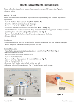
2. Run the 1/2" O.D- line from the feedwater connection at the main
water line to the inlet feedwater valve on the prefilter assembly.
Remove the compression nut from this valve (Fig 3, Item 2) and
slide it onto the tubing followed by a Delrin (white plastic) sleeve.
(See Fig. 9) Note that there may be a brass sleeve inside the
compression nut Discard the brass sleeve. Connect the tubing to the
valve by inserting the tubing all the way into the fitting and
tightening the compression nut.
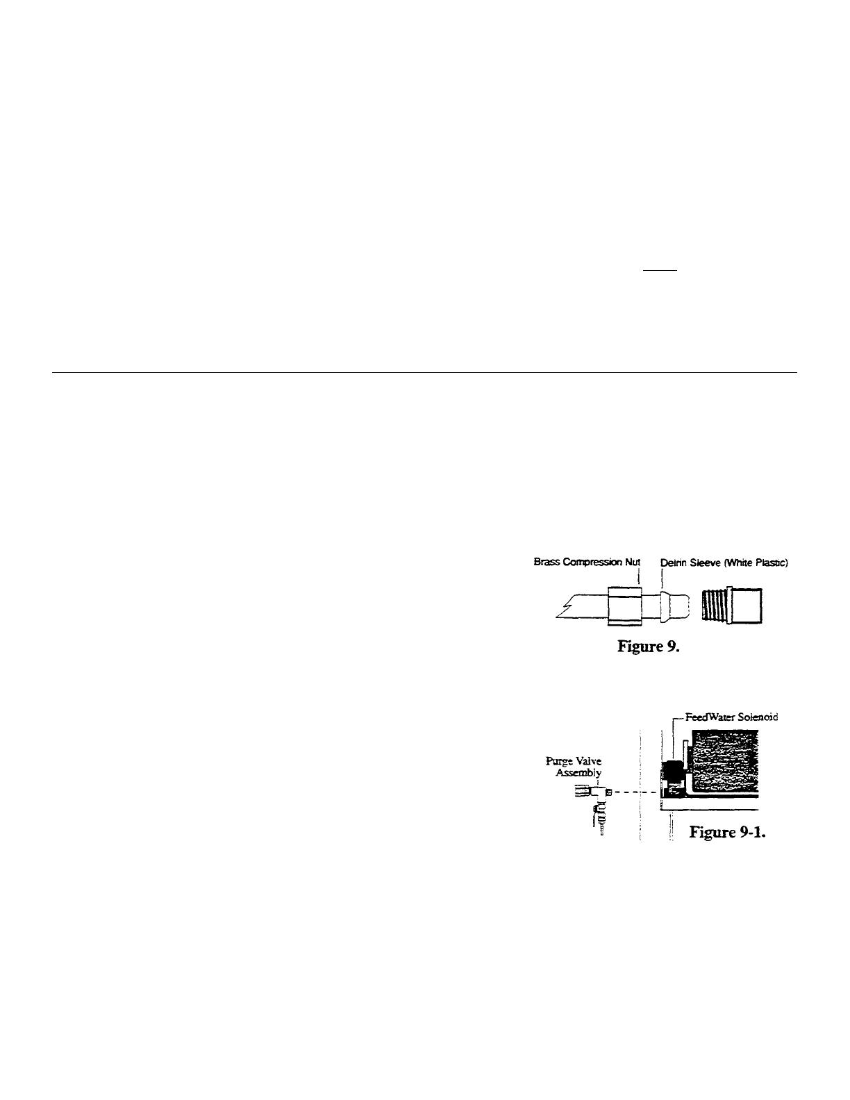
3. Install the purge valve assembly by threading it into the female
threads on the feed water solenoid. (Fig. 9-1)
4. Remove the compression nut from the prefilter assembly outlet
connection (Fig. 3, Item 5). Slide the compression nut and a Delrin
sleeve onto one end of a piece of 1/2" O.D. tubing Connect this end
of the tubing to the prefilter assembly outlet connection. Route the
tubing in a gradual arc down and to the left, behind the post
treatment filter, and up to the feedwater inlet connection on the
purge valve assembly (Fig.3, Item 9). Avoid sharp bends. Do not kink the tubing. Cut the tubing using a plastic
tubing cutter or razor knife. Make a smooth, clean, 90° cut or leaks may result. Slip a compression nut and Delrin
sleeve over the end and connect the tubing to the feedwater solenoid.
9
Cleveland Range Installation, Operation and Maintenance Manual
Drain connection
1. Run 3/8" O.D. (1/4" nominal) tubing from the reject drain connection (Fig. 3, Item 17) to the drain. Use the 3/8"
Delrin (white plastic) sleeve provided on the connection to the brass compression fitting at the drain connection.
2. The drain is pressurized and may be run up to 10 feet above the RO or up to 25 feet from the RO to the drain. Care
must be taken not to crimp or block the drain line.
3. Run a line from the purge valve on the inlet to the RO (Fig. 3, Item 26) to the drain or leave the end accessible for
purging the filters into a bucket.
Important: An approved air gap should exist between the RO unit and the drain opening to meet local plumbing
codes.
Product water connection
1. Remove the plastic compression nut from the
product water outlet connection on the RO. (Fig. 3,
Item 10) Slide the nut, me stainless steel grip ring,
the plastic washer and the''O" ring, (Fig. 10) about
1/4" past the end of a piece of 3/8" O.D. (1/4"
nominal) tubing. Insert the assembly into the product
water outlet connection and tighten me compression
nut
2. Run this line down to the inlet side of the post
treatment filter (Fig. 3, Item 8) and connect it
3. For connection of the post treatment filter to the
storage tank, see the storage installation instructions.
Electrical connection
Be certain the red handled "ON/OFF'' switch on the RO (Fig 3, Item 13) is in the "OFF'' position. DOWN IS
"ON" UP IS "OFF".
1. Connect the power cord from the RO to a 115 VAC, 15 AMP grounded receptacle.
2. Refer to the Start -Up section for further instructions.
10
Storage Tank Installation Procedure
The SteamerGard storage tanks are 10, 20 and 40 gallon, self pressurized storage tanks. As water from the RO fills the
tank, the pressure in the tank increases until it reaches 60 psi, at which point the RO will automatically turn off. As water is
drawn from the tank, the pressure in the tank drops. When the pressure in
the tank drops to 40 psi, the RO will automatically mm on.
1. Install the ball valve kit onto the tank. (Fig 4.) Use approximately 4
wraps of Teflon tape (provided) to seal each of the connections.
Tighten the fittings approximately one mm past hand tight. Do not
over tighten. Over-tightening may crack the fittings.
2. We recommend the use of the elbow fitting included to direct the ball
valve up along the tank instead of connecting the ball valve directly
to the nipple. Using the elbow will result in a more compact
installation that is less vulnerable to breakage.
3. Check the air pressure in the tank- With no water in the tank, it
should be 15 psi. Add or remove air as required.
4. Place the tank in the desired location. It should be placed in an area
where it will not be frequently bumped or jarred.
5. Run a 3/8" O.D. polybutylene line from one side of the Tee to the
product water outlet on the post treatment assembly on the RO (Fig.
3, Item 6).
6. Open the ball valve on the tank by turning the handle until it's
parallel with the body of the valve.
11
Control Panel Installation, Connection to Steamer
The control panel provides a water quality monitor (Fig. 5, Item 6), bypass valve (Fig. 5, Item 4) and storage tank pressure
gauge (Fig. 5, Item 5). The water quality monitor measures the quality of water provided by the SieamerGard. If a red light is
noted, service is required. The bypass valve allows operation of the steamer on tap water in the event of failure of the
SteamerGard system.
1. Position the control panel on a wall in the vicinity of the
steamer (See Figure 2). You will also need access to a
cold water supply.
2. Mount the control panel to the wall using the four
#10x1 1/2" screws and wall anchors provided.
3. Tap into a cold water supply line near the control panel.
We recommend the installation of a ball valve at the
point you tap into the cold water supply. Run a line
from the cold water supply to the control panel. If the
distance is 25' or less, use 3/8" O.D. polybutylene
tubing. For longer runs, use 1/2' O.D. tubing and reduce
down at the control panel. Connect this line to the
"Bypass" fitting (Fig. 5, Item 2) on the control panel.
4. Connect a 3/8" O.D. polybutylene line to the open end
of the Tee on the storage tank. Run this line from the
tank to the SteamerGard connection on the control
panel. (Fig. 5, Item 1)
5. Connect a 3/8" O.D. polybutylene line to the outlet on the control panel (Fig. 5, Item 3). Connect me other end of this
line to the steam generator (boiler) connection on the steamer. Install a check valve as directed in the steamer manual
at the inlet connection to the steam generator. The fitting and check valve required to make this connection are not
included in the SteamerGard system.
NOTE: Do not connect the purified water to the condenser. The condenser must be connected to a separate
cold water supply.
The SteamerGard installation is now complete. You can now start-up the steamer
by following the start-up instructions for the steamer.
12
Start-Up Procedures,
1. With all connections completed and checked and the ON/OFF switch (Fig 3. Item 13) still in the "OFF'' (up) position,
open the main feed water supply valve and the prefilter assy. shut-off valve (Fig 3, Item 1)
2. Turn the pressure control valve (Fig 3, Item 11) several turns counterclockwise until the handle feels loose. The lock-
nut on the threaded shaft may have to be loosened.
3. Open the purge valve at the inlet to the RO system.(Fig. 3, Item 26). Allow the water to drain until all of the air is
purged. Close the drain valve.
4. Turn the power switch to the "ON'' (down) position. The motor should start running and the operating pressure gauge
should read less than 150 PSI. Gradually open the flush valve (Fig 3, Item 16) to help expel air from the system. The
system may temporarily cycle on and off. If this occurs, slowly turn the flush valve toward the closed position until
cycling stops. When air is purged and water flow stabilizes (30 to 60 seconds), close the flush valve.
5. Slowly mm the pressure control valve knob clockwise until the pressure gauge (Fig 3, Item 15) reads 175 psi.
Maximum operating pressure is 175 psi. When set, tighten the lock-nut on the control valve shaft.
DO NOT set the operating pressure as read by this gauge at anything higher than 175 psi. Operating at higher
pressures will subject the system to pressures greater than it is designed for.
6. While the storage tank is filling, inspect the pretreatment assembly, RO system and all connections for leaks and make
necessary adjustments.
7. When the storage tank is full, the RO will automatically shut off. It is important to verify that the RO shuts off when
the storage tank is full. To verify proper operation, check the pressure gauge on the control panel (Fig. 5, Item 5) and
observe that the system shuts off at 60 psi. Use the chart below to determine the time necessary for the RO to fill the
tank.
Model Fill Time, 10 gal. tank Fill Time, 20 gal. tank Fill Time, 40 gal. tank
WT
300
45
to
90
minutes
1.5
to
3
hours
3
to
6
hours
WT-600 23 to 45 minutes 45 to 90 minutes 1.5 to 3 hours
WT-900 20 to 30 minutes 30 to 60 minutes 1 to 2 hours
The RO will resume operation when the tank pressure drops to approximately 40 psi.
NOTE: The feedwater and storage tank pressure switches are factory calibrated and should not be altered. If you feel
pressure switch adjustment is required, consult with your dealer and refer to the instructions for adjustment on
the inside of the pressure switch cap.
8. Check for leaks in the fittings on the tank, the RO the control panel and steamer. Correct leaks as necessary.
9. Check the control panel to make sure that it is in the "SteamerGard" position (Fig. 5, Item 4).
13
Routine Maintenance
Routine maintenance is essential for consistent performance and long system life. The required routine maintenance consists
of changing the sediment and carbon prefilters. Since maintenance frequency will range from 3 to 6 months depending on
the properties of your feedwater, it's important that you consult with your distributor or the factory for recommended
maintenance frequency for your system.
De-pressurization Procedure
Prior to changing any prefilters, the feedwater must be shut off and the system must be depressurized. To do this:
1. If the steamer is running, switch the steamer to the "Bypass" position at the control panel.
2. If the RO is running, turn it off by switching the ON/OFF switch to the OFF (up) position.
3. Close the feedwater shut-off valve on the prefilter assembly by turning its handle until it is perpendicular to the
valve body.
4. Open the purge valve at the inlet to the RO system (Fig. 3, Item 26). This will relieve the pressure from prefilter.
Although the system is de-pressurized, the filter bowls will still be full of water when removed.
Sediment Prefilter Replacement Procedure
1. De-pressurize the system.
2. Locate the sediment prefilter (Fig. 3, Item 3). To remove the sediment prefilter, unscrew the filter bowl to the left
(counterclockwise as viewed from the bottom), using a filter bowl wrench or by hand. Empty the water and remove
the filter from the bowl and discard it.
3. Inspect the O-ring seals for damage. The O-rings should be replaced if they are damaged or distorted. Clean the
filter bowls with warm water and soap. Chemically disinfect the filter bowl if desired (household bleach can be
used, 1/2 teaspoon in a filter bowl of water).
4. Insert the new prefilter into the filter bowl. Screw the filter bowl onto the filter head by hand or use the filter
wrench. Be careful not to over tighten if you are using the filter wrench.
14
Routine Maintenance Cont'd
Carbon Filter Replacement Procedure
1. De-pressurize the system.
2. Locate the carbon prefilters (Fig. 3, Item 4). To remove the carbon prefilters, unscrew the filter bowls to the left
(counterclockwise as viewed from the bottom), using a filter bowl wrench or by hand. Remove the filters from the
bowls and discard them.
3. Inspect the O-ring seals for damage. The O-rings should be replaced if they are damaged or distorted. Clean the
filter bowls with warm water and soap.
4. Insert the new carbon prefilters into the filter bowls. Screw the filter bowls onto the filter heads by hand or use the
filter wrench. Be careful not to over-tighten if you are using the filter wrench.
Post Treatment Filter Replacement Procedure
1. De-pressurize the system.
2. Close the ball valve on the storage tank.
3. Locate the posttreatment filter (Fig. 3, Item 7). Loosen the black plasic nut on the inlet fitting to relieve pressure.
Use a small container to catch any spillage. Carefully open the housing. Remove the filter from the bowls and
discard it.
4. Inspect the O-ring seals for damage. The O-rings should be replaced if they are damaged or distorted. Insert the
new posttreatment filter into me filter bowl. Screw the filter bowl onto the filter head by hand or use the filter
wrench. Be careful not to over-tighten if you are using the filter wrench.
Final Inspection
Check to see that the;
s Prefilter bowl(s) have been tightened.
s RO power switch is in the OFF position.
s Rush valve is open.
s Valves are closed on hydropnuematic storage tanks - left open on atmospheric tanks.
s Point of use is open with hydropnuematic storage - closed with atmospheric storage.
Restarting and Purging the RO system
1. Open the feedwater valve on the prefilter assembly. The drain valve on the final carbon filter should still be open.
Purge air from the prefilters by allowing water to flow out of the drain valve until you see a steady, air free stream
of water. Close the drain valve.
3. Inspect prefilter bowl(s) for leaks and make adjustments if necessary.
4. Turn the power switch to the "ON" (down) position.
5. Open the ball valve on the storage tank if it had been closed.
6. Switch the control panel from "Bypass" back to "SteamerGard".
Your SteamerGard system routine maintenance is now complete.
15
16
  • Page 1 1
  • Page 2 2
  • Page 3 3
  • Page 4 4
  • Page 5 5
  • Page 6 6
  • Page 7 7
  • Page 8 8
  • Page 9 9
  • Page 10 10
  • Page 11 11
  • Page 12 12
  • Page 13 13
  • Page 14 14
  • Page 15 15
  • Page 16 16
  • Page 17 17
  • Page 18 18

Cleveland WT-300 User manual

Type
User manual
This manual is also suitable for

Ask a question and I''ll find the answer in the document

Finding information in a document is now easier with AI