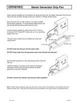
Page is loading ...

Cleveland Range
SteamCraft
3.1®
COUNTER TYPE
CONVECTION STEAMER
SERVICE
MANUAL
Model 21-CET-8
Printed
12/90
Cts
-
01

Cleveland WARRANTY AND LIMITED EXTENDED
WARRANTY COVERAGE
LIMITED WARRANTY
Cleveland Range products are warranted to the original purchaser to be free from defects in material and
workmanship under normal use and service for the standard warranty period.
Cleveland Range agrees to repair or replace, at its option. f.o.b. factory, any part which proves to be
defective due to defects in material or workmanship during the warranty period, providing the equipment has
been unaltered. and has been PROPERLY INSTALLED MAINTAINED. AND OPERATED IN ACCORDANCE
WITH THE CLEVELAND RANGE OWNER'S MANUAL
CLEVELAND RANGE agrees to pay any FACTORY AUTHORIZED EQUIPMENT SERVICE AGENCY
(within the continental United States. Hawaii, and Canada) for reasonable tabor required to repair or replace,
at our option. f.o.b. factory, any pan which proves to be detective due to defects in material or workmanship,
during the labor warranty period. This warranty includes travel time not to exceed two hours and mileage not
to exceed 50 miles (100 mites round-trip), but does not include post start-up, tightening loose fittings, minor
adjustments, maintenance. cleaning or descaling.
The standard labor warranty allows factory payment of reasonable labor required to repair or replace such
defective pans. Cleveland Range will not reimburse the expense of labor required tor the repair or
replacement of parts after the standard warranty period, unless an Extended Labor Warranty Contract has
been purchased equipment for the balance of the warranty period from the date of equipment installation,
start-up or demonstration
PROPER INSTALLATION IS THE RESPONSIBILITY OF THE DEALER. THE OWNER-USER. OR
INSTALLING CONTRACTOR. AND IS NOT COVERED BY THIS WARRANTY Many local codes exist and it
is the responsibility of the owner and instalter to comply with these codes. Cleveland Range equipment is
built to comply with applicable standards for manufacturers, including UL. A.G.A.. NSF. ASME/Ntl. Bd.. CSA.
CGA. ETL. and others.
BOILER (Steam Generator) MAINTENANCE IS THE RESPONSIBILITY OF THE OWNER-USER. AND IS
NOT COVERED BY THIS WARRANTY. The use of good quality feed water is the responsibility of the Owner-
User (see Water Quality Requirements below). THE USE OF POOR QUALITY FEED WATER WILL VOID
EQUIPMENT WARRANTIES. Boiler maintenance supplies, including boiler hand gaskets, are not warranted
beyond the first 90 days after the date the equipment is placed into service if no preventive maintenance
records are available showing des-caling every 90-120 days.
WATER QUALITY REQUIREMENTS
TOTAL DISSOLVED SOLIDS less than
60
parts per million
TOTAL ALKALINITY less than
20
parts per million
SlLICA
less than
13
pans per million
CHLORIDE less than
30
parts per million
pH FACTOR
greater than
75
The foregoing shall constitute the sole and exclusive remedy of original purchaser and the for any breach of warranty.
THE FOREGOING IS EXCLUSIVE AND IN LIEU OF ALL OTHER WARRANTIES. WHETHER WRITTEN. ORAL. OR
IMPLIED. INCLUDING ANY WARRANTY OF PERFORMANCE. MERCHANTABILITY. OR FITNESS FOR PURPOSE.
AND SUPERSEDES AND EXCLUDES ANY ORAL WARRANTIES OR REPRESENTATIONS. OR WRITTEN
WARRANTIES OR REPRESENTATIONS. NOT EXPRESSLY DESIGNATED IN WRITING AS A "WARRANTY" OR
"GUARANTEE" OF CLEVELAND RANGE MADE OR IMPLIED IN ANY MANUAL. LITERATURE. ADVERTISING
BROCHURE OR OTHER MATERIALS.
Cleveland Range's liability on any claim of any kind. including negligence, with respect to the goods or services
hereunder: shall in no case exceed the price of the goods or services, or pan thereof, which gives rise to the claim. IN NO
EVENT SHALL CLEVELAND RANGE BE LIABLE FOR SPECIAL. INCIDENTAL. OR CONSEQUENTIAL DAMAGES, OR
ANY DAMAGES IN THE NATURE OF PENALTIES.
LIMITED EXTENDED WARRANTY COVERAGE
The purchase of a Limited Extended Warranty Contract extends the standard warranty coverage to the
purchased period of time (one to four years) from the date of installation, start-up, or demonstration,
whichever is sooner.
Revised 1/1/93

PROTECTING WARRANTY COVERAGE
The warranty printed to the left specifies the owner/user's responsibility for proper
installation, operation, and maintenance of the SteamCraft 3.1. If these responsibilities
are not met, the Limited Warranty and/or Extended Limited Warranty coverage may be
adversely affected. The following table is provided to assist the owner/user in meeting
these responsibilities. In addition, the warranty advantages of installing a SteamerGard
water treatment system are explained after the table.
The Warranty Protection Table lists installation, operation, and maintenance factors
that have in the past adversely affected warranty coverage. The owner/user of a
SteamCraft 3.1 should pay particular attention to these factors to protect his warranty
coverage. This table is not a comprehensive list of the owner/user's responsibilities.
Cleveland Range steam products are intended for use only by professionally trained
personnel. To meet his responsibilities, the owner/user must supplement this guide
with any additional actions consistent with the operation of steam generating food
preparation equipment by a trained professional.
Warranty Protection Table
SUBJECT PAGE
REFERENCE
Electrical Power Requirements and Line Voltage…………………6 and 17
Water Quality Requirements and Analysis………………………………….6
Water Pressure……………………………………………………………….18
Vented Drain…………………………………………………………………..14
Level Operation……………………………………………………………….10
Blowdown Frequency………………………………………………..41 and 52
Steam Generator Maintenance and Maintenance Records………………55
Descaling Frequency and Procedure……………………………………….56
Approved Chemical Cleaners………………………………………………..56
Authorized Maintenance and Repair………………………………………..61
SteamerGard Water Treatment System
A SteamerGard water treatment system protects the SteamCraft 3.1 from impurities
contained in regular tap water, especially Total Dissolved Solids (TDS) which cause
lime and scale deposits in steamer equipment The protection is so effective that
Cleveland Range increases the warranty coverage on a SteamCraft 3.1 installed in
conjunction with a SteamerGard system to five years for parts and three years for labor
on water related components, elements, valves, generators, piping, etc. However, even
with a SteamerGard system installed, the owner/user should follow the guidance of the
Warranty Protection Table.

Model 21-CET-8 Service Manual Page I
TABLE OF CONTENTS
CHAPTER PAGE
CHAPTER 1. PRODUCT IDENTIFICATION……………………………………………………………….1
MODEL NUMBER…………………………………………………………………………………….1
SERIAL NUMBER…………………………………………………………………………………….1
PRODUCT INFORMATION PLATE…………………………………………………………………1
CHAPTER 2. INSTALLATION INSTRUCTIONS……………………………………………………………3
INTRODUCTION………………………………………………………………………………………3
INSTALLATION POLICIES……………………………………………………………………………3
INSTALLATION OVERVIEW…………………………………………………………………………4
PREPARATION FOR INSTALLATION………………………………………………………………6
Electric Power Requirements…………………………………………………………………6
Water Quality Requirements…………………………………………………………………6
Water Supply System…………………………………………………………………7
Selecting The Operating Location……………………………………………………………7
INSTALLATION INSTRUCTIONS…. ………………………………………………………………..9
Unpacking and Inspection…………………………………………………………………….9
Shipping Damage Instructions……………………………………………………..10
Position and Level The Steam Craft 3.1…………………………………………………..10
Leg Mounting and Leveling…………………………………………………………10
Surface Mounting and Leveling…………………………………………………….11
Stand Mounting and Leveling……………………………………………………….12
Install Slide Racks……………………………………………………………………14
Install the Free Air Vented Drain Lines……………………………………………………..14
Connect Drain Line……………………………………………………………………………16
Install Electric Power Lines………………………………………………………………….16
Connect Electrical Line………………………………………………………………………17
Install Water Supply Lines…………………………………………………………………..18
Connect Water Supply Lines………………………………………………………………..20
General Connection Requirements………………………………………………..21
Untreated Water Connection (Without SteamerGard)…………………………..21
Treated Water Connection (With SteamerGard)…………………………………21
Testing Water Supply Lines…………………………………………………………………21
Final Setup and Checkout…………………………………………………………………..22
Setup and Blowdown Inspection – All SteamCraft 3.1’s………………………..22
Operating Tests – Key Pad Control Panel……………………………………….24
Operating Tests – Dial Timer Control Panel……………………………………..26
Printed 12/90

Page ii Model 21-CET-8 Service Manual
Table of Contents (continued)
CHAPTER PAGE
CHAPTER 3. OPERATION 29
INTRODUCTION 29
OPERATIONAL SAFETY 29
CONTROL PANELS 30
KEY PAD CONTROL PANEL SUMMARY 31
COOKING OPERATIONS- KEYPAD CONTROL PANEL 32
Manual and Timed Modes 32
Main Power Switch 32
Power ON (Automatic Fill) 34
Inspect the Cooking Compartment 34
Preheating the SteamCraft 3.1 35
Operating Procedure - Timed Mode 36
Operating Procedure - Manual Mode 39
Manual Timer 39
Temperature Compensation 39
Manual Cooking Procedure 40
Power OFF (Automatic Blowdown) 41
Blowdown Frequency 41
Blowdown Procedure 42
Shut Down and Cleaning (At end of day or shift) 42
DIAL TIMER CONTROL PANEL SUMMARY 44
COOKING OPERATIONS-DIAL TIMER CONTROL PANEL 44
Manual and Timed Modes 46
Main Power Switch 46
Power ON (Automatic Fill) 46
Inspect the Cooking Compartment 47
Preheating the SteamCraft 3.1 47
Operating Procedure - Timed Mode 48
Operating Procedure - Manual Mode 50
Manual Timer 50
Manual Cooking Procedure 50
Power OFF (Automatic Blowdown) 52
Blowdown Frequency 52
Blowdown Procedure 52
Shut Down and Cleanin
g
(At end of day or shift)
53
Printed 12/90

Model 21-CET-8 Service Manual Page iii
Table of Contents (continued)
CHAPTER PAGE
CHAPTER 4. PREVENTATIVE MAINTENANCE AND TROUBLESHOOTING…………………………………….55
INTRODUCTION……………………………………………………………………………………………….55
MAINTENANCE RECORDS…………………………………………………………………………………..55
DAILY MAINENTANCE………………………………………………………………………………………55
Clean SteamCraft 3.1…………………………………………………………………………………..55
WEEKLY MAINTENANCE……………………………………………………………………………………55
MONTHLY MAINTENANCE…………………………………………………………………………………56
YEARLY MAINTENANCE……………………………………………………………………………………59
TROUBLESHOOTING NOTES………………………………………………………………………………..61
CHAPTER 5. ELECTRICAL SYSTEM………………………………………………………………………………….63
INTRODUCTION……………………………………………………………………………………………….63
Figures And Illustrations……………………………………………………………………………….63
STEAMCRAFT 3.1 ELECTRICAL CIRCUITS………………………………………………………………..63
High Voltage Circuit……………………………………………………………………………………63
120 VAC Circuit……………………………………………………………………………………….63
Timer Circuits………………………………………………………………………………………….64
CIRCUIT OPERATION………………………………………………………………………………………...64
MANUAL Mode Circuit Operation……………………………………………………………………64
TIMED Mode Circuit Operation………………………………………………………………………67
Electronic Key Pad Timer Units..…………………………………………………………….68
Mechanical Dial Timer Unit……………………………….…………………………………68
Shutdown, Steam Generator Blowdown, and Float Cylinder Rinse..………………………………….68
ELECTRICAL CIRCUIT COMPONENTS…………………………………………………………………….70
Terminal Block (4, Figure 6-7)………………………………………………………………………..70
Heater Element (4, Figure 6-9)………………………………………………………………………..70
Dryer Element (7, Figure 6-8)…………………………………………………………………………71
Fuses (8, Figure 6-7)…………………………………………………………………………………..71
ON/OFF Switch (10, Figure 6-5)……………………………………………………………………...71
TIMED/MANUAL Switch (11, Figure 6-5)…………………………………………………………..72
Relay……………………………………………………………………………………………………72
3-Minute Timer (14, Figure 6-5)……………………………………………………………………….73
Rinse Solenoid Valve (1, Figure 6-11)…………………………………………………………………73
Drain Solenoid Valve (4, Figure 6-12)…………………………………………………………………73
Fill Solenoid Valve (1, Figure 6-11)……………………………………………………………………73
Condenser Solenoid Valve (1, Figure 6-11)……………………………………………………………74
Timer…………………………………………………………………………………………………...74
Electronic Key Pad Timer (3, Figure 6-5)……………………………………………………74
Compartment Thermal Switch (Electronic Key Pad Units Only)(17, Figure 6-5)…………..75
Printed 12/90

Page iv Model 21-CET-8 Service Manual
Table of Contents (continued)
CHAPTER PAGE
CHAPTER 5. ELECTRICAL SYSTEM (continued)
Mechanical Timer (3, Figure 6-6)………………………………………………………………75
3-Second Timer and Buzzer (Mechanical Timer Units Only)(11, 15, Figure 6-6)…………….75
High Temperature Limit Switch (1, Figure 6-9)…………………………………………………………75
Float Assembly (Figure 6-10)……………………………………………………………………………75
COMPONENT TESTING GUIDE INTRODUCTION…………………………………………………………..77
Nominal Voltage…………………………………………………………………………………………77
FUNDAMENTAL COMPONENT TESTING……………………………………………………………………77
Visual Check…………………………………………………………………………………………….77
Fuses……………………………………………………………………………………………………..78
Connection Points and Wiring…………………………………………………………………………..78
Solenoid Valves…………………………………………………………………………………………78
Timers……………………………………………………………………………………………………79
Thermostatic Snap Switches…………………………………………………………………………….79
Heater Element…………………………………………………………………………………………..80
Resistance Measurements………………………………………………………………………………..80
Insulation Resistance Measurements…………………………………………………………………….80
Voltage Measurements…………………………………………………………………………………..80
COMPONENT TEST PROCEDURES……………………………………………………………………………81
Initial Conditions For All Testing………………………………………………………………………..81
Fuses……………………………………………………………………………………………………...81
Transformer………………………………………………………………………………………………82
ON/OFF Switch………………………………………………………………………………………….83
Relay K1…………………………………………………………………………………………………83
Fill Solenoid Valve………………………………………………………………………………………84
3-Minute Timer………………………………………………………………………………………….85
Drain Solenoid Valve……………………………………………………………………………………86
Rinse Solenoid Valve……………………………………………………………………………………87
Condenser Solenoid Valve………………………………………………………………………………88
TIMED/MANUAL Switch………………………………………………………………………………89
High Temperature Limit Switch…………………………………………………………………………90
Electronic Key Pad Timer……………………………………………………………………………….90
Compartment Thermal Switch (Key Pad Timer Units Only)……………………………………………92
Mechanical Timer………………………………………………………………………………………..93
Heater Contactor…………………………………………………………………………………………93
Heater and Dryer Elements………………………………………………………………………………95
Float Assembly…………………………………………………………………………………………..96
3-Second Timer and Buzzer (Mechanical Timer Units Only)…………………………………………..99
Printed 12/90

Model 21 -CET-8 Service Manual Page v
Table of Contents (continued)
CHAPTER PAGE
CHAPTER 6. ILLUSTRATED PARTS LISTS……………………………………………………………………………101
INTRODUCTION………………………………………………………………………………………………..101
Parts Differences Among SteamCraft 3.1 Steamers…………………………………………………….101
Electrical Schematics and Wiring Diagrams…………………………………………………………….101
Printed 12/90


Model 21-CET-6 Service Manual Page 1
CHAPTER 1. PRODUCT IDENTIFICATION
Cleveland Range, Inc. assigns two product identification numbers to each
SteamCraft 3.1: a model number and a serial number. The model number
identifies the product characteristics. The serial number identifies the
individual unit
MODEL NUMBER
All SteamCraft 3.1 steamers are identified by the same model number, 21-
CET-& Each character of this model number identifies a characteristic of
the steamer. The SteamCraft 3.1 is a Convection steamer, Electric
powered, and Table-mounted with an input energy rating of 8-5 kW. This
manual covers all standard features and options available on SteamCraft
3.1 steamers.
Other than selection of options, there are presently no significant design,
parts, or operating differences among steamers with this model number.
Figure 1-1 illustrates the SteamCraft 3.1 and identifies the major com-
ponents.
SERIAL NUMBER
During manufacture, SteamCraft 3.1's are assigned individual serial
numbers. A typical SteamCraft 3.1 serial number is: WC-7350-90G-02. The
left half of the number carries design information. The right half of the
number contains the manufacturing date and the unit of the manufacturing
lot The date of our sample number is 90G-02: 90= 1990, G=July. 02=the
second unit of the manufacturing lot Serial numbers are used when
explaining differences in design, parts, or operation among units with the
same model number. For example: a particular part may be used on
SteamCraft 3.1's with serial numbers before WC-7350-90G-02, and a
different part used on steamer WC-7350-90G-02 and those manufactured
after it
PRODUCT INFORMATION PLATE
The Product Information Plate on the back of the unit lists the model and
serial number of the steamer. Refer to Figure 1-1 for the location of the
plate. Figure 1-2 illustrates a typical SteamCraft 3.1 Product Information
Plate. The plate also lists power and wiring requirements.
Figure 1-2. SteamCraft 3.1 Product Information Plate

Model 21-CET-8 Service Manual Page 3
CHAPTER 2. INSTALLATION INSTRUCTIONS
INTRODUCTION
This chapter is a guide for installation of the SteamCraft 3.1, model number
21-CET-8. The instructions are written for qualified, professional plumbers,
pipe fitters, and electricians. This guide does not include all procedures and
precautions in the common domain of licensed plumbers, pipe fitters, and
electricians, or experienced food service equipment installers. These
instructions must be used in conjunction with a thorough understanding of
the Basic Plumbing Code of the Building Officials and Code Administrators
International, Inc. (BOCA), the National Fuel Gas Code, ANSI Z223.1-
1984, and the Food Service Sanitation Manual of the Food and Drug
Administration (FDA).
Before starting installation, the owner and the installer should read through
this chapter and thoroughly understand and agree upon:
• The installation policies of Cleveland Range, Inc. as stated in Installation
Policies.
• Responsibility for electric power requirements as described in
Preparation for Installation, Electric Power Requirements.
• Responsibility for feed water quality and its testing as described in
Preparation For Installation, Water Quality Requirements.
WARNINGDEATH, INJURY, AND
EQUIPMENT DAMAGE
WARNING
DEATH, INJURY, AND EQUIPMENT DAMAGE could result
from improper installation of the SteamCraft 3.1, or from
installation of a unit damaged during shipment or storage.
Either of these conditions could also void the equipment
Warranty.
DO NOT INSTALL a SteamCraft 3.1 suspected of
damage.
Install the SteamCraft 3.1 according to the policies and
procedures outlined in this manual.
INSTALLATION POLICIES
• The SteamCraft 3.1 must be installed by qualified plumbing and electrical
personnel, working to all applicable national and local codes. Equipment
installation must comply with the Basic Plumbing Code of the Building
Officials and Code Administrators International, Inc. (BOCA) and the
Food Service Sanitation Manual of the Food and Drug Administration
(FDA).
• Cleveland Range designs and manufactures equipment to comply with
applicable standards for manufacturers. Included among these
certification agencies are: UL, A.G.A, ASME/N.Bd, NSF, CSA. CGA,
ETL, and others.

Page 4 Model 21 -CET-8 Service Manual
• This equipment is designed and certified for safe operation only
when permanently installed in accordance with local and/or national
codes. Many local codes exist, and it is the responsibility of the
owner and installer to comply with these codes.
• In no event shall the manufacturer assume any liability for damage
or injury resulting from installations which are not in strict
compliance with the Installation Instructions and the codes cited
above. Specifically, the manufacturer will not assume any liability for
damage or injury resulting from improper installation of equipment,
including, but not limited to, temporary or mobile installations.
INSTALLATION OVERVIEW
Schematic Installation Diagram, Figure 2-1, illustrates the various drain,
electrical, and water lines required; and their connection points on the
SteamCraft 3.1. Table 2-1, Installation Check List, outlines the overall
installation process in a recommended sequence; the instructions refer-
enced provide details. Installation requirements may vary from site to
site; adapt the check list accordingly.
Table 2-1. Installation Check List
TASK PAGE
REFERENCE
COMPLETED
Preparation
Check Electric Power Requirements 6
Test Supply Water Quality 7
Select Water Supply System 7
Install Water Treatment System 7
Select Operating Location 7
Installation
Unpack And Inspect SteamCraft 3.1 9
Position And Level Steamer 10
Install And Connect Drain Line 14-16
Install And Connect Electrical Lines 16-18
Install And Connect Water Supply Lines 18-21
Test Water Supply Lines 21
Perform Final Setup And Checkout 22

Model 21-CET-8 Service Manual Page 5
INSTALLATION DIAGRAM NOTES
1. The Product Identification Plate located on the
back panel specifies the electric power
requirements.
2. For each unit, the installer must provide a ground
connection and a separate fused disconnect
switch.
3. Catastrophic damage will result from shifting the
SteamCraft 3.1 more than 10° out of level while
power is turned on at the unit's main power
switch.
4. The unit must have a cold water supply, NOT
HOT. The water supply must meet the quality
requirements of Table 2-2. and the pressure
requirements on page 18
5. A SteamerGard system is recommended when
water quality does not meet the Table 2-2
requirements.
6. A manual shut off valve must be installed
between the main water supply and the steamer
supply lines. Refer to figures 2-18 and 2-19 for
the recommended component arrangements.
7. Run a single water line between the main cold
water supply and the tee. The separate steam
generator and condenser/blowdown supply fines
are comparatively short.
& The drain line must have a gravity flow away from
the steamer, and must not be connected to the
drain lines of any other equipment
9. The drain line must be free air vented. If the line
empties into a floor drain, there must be a one
inch minimum clearance between the drain line
and the floor drain openings.
Figure 2-1. Schematic Installation Diagram

Page 6 Model 21 -CET-8 Service Manual
PREPARATION FOR INSTALLATION
Before unpacking the SteamCraft 3.1 check the electric power and water
quality requirements and select the operating location.
Electric Power Requirements
The characteristics of the electric power supply must match the power
requirements specified on the SteamCraft 3.1 product identification plate.
The plate is located on the back of the unit as illustrated in Figure 2-2.
Water Quality Requirements
CAUTION
Using water not within the limits specified in this
manual could void or adversely affect Cleveland
Range's warranty coverage of the SteamCraft 3.1.
As with any steam generating equipment, poor water quality degrades
SteamCraft 3.1 performance. If feed water is low in Total Dissolved
Solids (TDS) and free of paniculate matter, the steam generator,
heating element, and valves of the SteamCraft 3.1 will give years of
trouble-free service with a minimum of maintenance.
In some areas, even potable tap water contains a variety of impurities
that can cause costly problems in steam generating equipment Of
primary concern are mineral salts and other impurities which remain
behind as lime or scale deposits during the steam generating
process. These deposits have caused components to fail, including
heating elements, probes, and solenoid valves. Of equal importance
is the decrease in heat transfer efficiency caused by lime and scale
deposits. Decreased heat transfer increases water and power
consumption. Use of the SteamCraft 3.1 in areas with poor water
quality requires installation of a SteamerGard water treatment system
or increased frequency of maintenance, cleaning, and descaling.

Model
21
-
CET
-
8 Service Manual Page
7
Check the quality of supply water as described below before starting
construction of the water supply lines. If a SteamerGard water treatment
system must be installed to achieve acceptable water quality, install it
before connecting the water supply lines to the SteamCraft 3.1.
Contact a local water treatment specialist for an on-the-premises water
analysis. The recommended minimum feed water quality requirements for
the SteamCraft 3.1 are listed in Table 2-2.
Table 2-2. Minimum Water Quality Requirements
Total Dissolved Solids less than 60 parts per million
Silica
less than 13 parts per million
Alkalinity
less than 20 parts per million
ph factor
greater than 7.5
Water Supply System
Select a water supply system that fulfills the requirements of the limits
listed in Table 2-2 The supply must provide a minimum dynamic pressure
of 35 osi (2.4 kg/cm
2
) and a maximum static pressure of 60 psi
(4.1 kg/cm). Refer to page 18 for detailed pressure and fitting
requirements, and recommended plumbing layouts.
• If analysis shows that the supply water is within the required limits, a
single fine water system can be installed. A single water line system is
illustrated in Figure 2-18 on page 18.
• If analysis shows that the supply water is NOT within the required limits,
install a SteamerGard water treatment system. Figure 2-19 on page 19
illustrates a treated water supply arrangement.
• If analysis shows that the supply water is NOT within the required Limits,
and it is not possible to install a SteamerGard water treatment system;
plan on increasing the frequency of maintenance, cleaning, and
descaling beyond that recommended in the maintenance schedule
(Chapter 4).
Selecting The Operating Location
For safe and efficient operation, observe the following criteria when
selecting an operating location for the SteamCraft 3.1.
1. The SteamCraft 3.1 fits in a small counter space. Figure 2-3 illustrates
the dimensions and clearances required. Maintain the following min-
imum dimensions around the unit for safe and efficient operation,
maintenance and service.
• A 3 inch clearance around the unit for ventilation.
• A 12 inch clearance on the right side for removing the service panel
during descaling, maintenance and repair.
• A3 inch clearance at the rear for the water inlet fittings, and the
maximum size (2-inch NPT) drain fittings.
• Approximately 22 inches in front of the unit for opening the door and
cafeteria pan clearance.

Page 8 Model 21 -CET-8 Service Manual
2. The SteamCraft 3.1 is typically installed with four adjustable
mounting legs, as shown in the dimension drawing. If clearance
above the unit is limited it can be installed without legs, surface
mounted directly to the counter top.
3. The SteamCraft 3.1 must be level both front to back and side to
side. Select an operating surface that is level enough to allow
leveling the unit without extreme adjustment of the legs or
shimming of surface mounts.
4. The SteamCraft 3.1 weighs approximately 135 pounds. The
counter area selected must be capable of supporting an operating
weight of approximately 175 pounds to include the weight of
water and food.
5. The SteamCraft 3.1 has capacity for three 12" x 20" x 25"
Cafeteria Pans (model # SP-25 or PP-25). Convenient storage for
pans should be considered when selecting the operating location.
6. Do not block the vents on the side or rear of the unit. Do not store
articles on top of the unit.
If a satisfactory counter location is not available, consider using a
model ES-2130 Equipment Stand. This stand, illustrated in Figure
2-4, is designed to support the SteamCraft 3.1, and meets the above
criteria.

Model 21-CET-8 Service Manual Page 9
INSTALLATION INSTRUCTIONS
After selecting the SteamCraft 3.1 operating location, the steamer can be
unpacked, positioned, and installed. After Final Setup and Checkout, the
SteamCraft 3.1 will provide years of reliable operation.
Unpacking and Inspection
1. Before unpacking the shipping carton, visually inspect it for damage.
• If the shipping carton appears damaged, do not open the carton.
Refer to the Shipping Damage Instructions on page 10.
• If the shipping carton is undamaged, proceed with step 2.
2. Slit the four comers of the carton and peel carton-sides away from the
SteamCraft 3.1. The slide racks and legs are shipped in separate
packing on top of the unit. Be careful not to damage or throw away
these unassembled parts.
3. Remove the carton from the top of the unit The package contains two
slide racks as illustrated in Figure 2-5. These racks are shipped in
separate packing on top of the unit
4. The SteamCraft 3.1 adjustable legs are also shipped on top of the unit in
pockets at the edges of the packing. Refer to Figure 2-6.
5. Open the door of the SteamCraft 3.1. Several pre-assembled parts can
be seen inside the unit. Refer to Figure 2-7. Do not remove the Drain
Screen, Steam Nozzles, and Slide Rack Mounting Pins.
6. Inspect the SteamCraft 3.1 and parts for damage or loss.
• If you discover or suspect shipping damage or loss, refer to the
Shipping Damage Instructions on page 10.
• If all items are accounted for and undamaged, place the packaged
slide racks inside the cooking compartment, and proceed to Position
and Level The SteamCraft 3.1.

Page 10 Model 21 -CET-8 Service Manual
Shipping Damage Instructions
If shipping damage to the SteamCraft 3.1 is discovered or suspected,
observe the following guidelines in preparing a shipping damage claim.
• Write down a description of the damage or the reason for suspecting
damage as soon as it is discovered. This will help in filling out the claim
forms later.
• As soon as damage is discovered or suspected, notify the carrier that
delivered the shipment
• Arrange for carrier representative to examine damage.
• Fill out all appropriate claims forms and have the examining carrier sign
and date each form.
Position and Level
The SteamCraft 3.1
The SteamCraft 3.1 is typically counter top mounted on four adjustable legs.
To compensate for height limitations, the steamer can be surface mounted
directly to the counter top. If a suitable counter is not available, the unit can
be secured to a Cleveland Range ES-2130 Equipment Stand. The following
instructions cover each of these mounting methods.
CAUTION
Malfunctions and equipment damage may result from
improper mounting. Malfunctions and/or damage resulting
from improper mounting are not covered by the equipment
warranty.
The SteamCraft 3.1 MUST BE LEVEL BOTH FRONT TO
BACK AND SIDE TO SIDE in all mounting arrangements.
Catastrophic damage will result from shifting the
SteamCraft 3.1 more than 10° out of level while power is
turned on at the unit's main power supply switch.
Leg Mounting and Leveling
The supporting legs of the SteamCraft 3.1 are four inches long when the
adjustable feet are fully retracted. This provides the four inch space below
the unit required by NSF sanitary standards. The adjustable feet can be
extended approximately two inches for leveling the steamer.
Assembly
1. Check that the feet are fully retracted into the legs. Do not over-tighten.
The feet should easily screw in and out using fingers only.

Model 21-CET-8 Service Manual Page 11
WARNING
INJURY AND EQUIPMENT DAMAGE could result
from improper lifting. The SteamCraft 3.1 weighs
approximately 135 pounds. Use enough workers with
experience lifting heavy equipment to place the
SteamCraft 3.1 on the counter.
2. Be sure electric power is turned off at the main power switch. Place the
SteamCraft 3.1 on its left side.
3. Screw the four legs into the weldnuts mounting boles. All four legs must
be installed for proper mounting of the SteamCraft 3.1.
4. Place the steamer upright on its four legs.
Positioning and Leveling
1. Thoroughly clean the counter top area that will support the steamer.
2. Using a level, determine and mark the highest comer of the counter top
area that will support the steamer.
3. Lift the SteamCraft 3.1 into position on the counter.
4. Do not adjust the retractable foot of the leg in the highest comer (marked
in step 2). Using a level, adjust the other three legs until the unit is level
both front to back and side to side.
5. After the SteamCraft 3.1 has been positioned and leveled, refer to page
14, and install the slide racks.
Printed 12/90
Figure
2
-
8.
Counter Top Mounting
Holes
Surface Mounting and Leveling
When a SteamCraft 3.1 is surface mounted (without legs), NSF standards
require a sanitary counter top seal between the counter surface and the
bottom of the unit This seal closes any gap between the unit and counter
top. A sanitary seal closing a gap greater than 1/4 inch may not meet NSF
sanitation standards. Therefore, do not surface mount the SteamCraft 3.1 to
a surface out of level more then 1/4 inch over the length or width of the unit.
Shimming the unit level may leave a gap too large to seal within NSF
standards.
1. Thoroughly clean the bottom perimeter of the steamer and the counter top
area that will support the steamer.
2. Using a level, determine and mark the highest comer of the counter top
area that will support the steamer. At each of the other three comers,
measure and note the shim thickness required to level the SteamCraft
3.1 both front to back and side to side.
3. Refer to Figure 2-8. Leaving the required clearance (shaded area) around
the unit, determine the exact front, back, and side lines of the SteamCraft
3.1 on the counter top. From these lines, locate and drill four 1/2 inch
diameter mounting holes in the counter, as shown in the diagram.

Page 12 Model 21 -CET-8 Service Manual
WARNING
INJURY AND EQUIPMENT DAMAGE could result
from improper lifting. The SteamCraft 3.1 weighs
approximately 135 pounds. Use enough workers with
experience lifting heavy equipment to place the
SteamCraft 3.1 on the counter.
Figure
2
-
9.
Counter Top
Mounting Hardware
Figure
2
-
10.
Sanitary Counter Top
Seal
4.
Lift the SteamCraft
3.1
into position on the counter and align the steamer
mounting holes with the counter mounting holes. The steamer mounting
holes are the holes with the 3/8"-16 weldnuts usually used to mount the
adjustable legs.
NOTE: If there is not enough clearance behind the steamer to install the drain,
electrical, and water lines; skip the remainder of this procedure and
go to page 14, Install the Free Air Vented Drain Lines. After installing
all necessary drain, electrical, and water lines, proceed with step 5 of
these instructions and mount the steamer to the counter top.
5. Install 3/8"-16 mounting screws and washers as shown in Figure 2-9. The
screws should be long enough to pass through the washer, counter,
shims, and weldnut without projecting more than 1/2 inch above the
weldnuL Thread the screws only a few turns into the weldnuts, leaving
enough play for leveling the unit and sealing the mounting holes.
6. Do not shim at the highest comer (marked in step 2). Shim the other three
comers until the unit is level both front to back and side to side.
7. Inject enough silicone sealant into each mounting hole in the counter to
seal the bole as the hardware is tightened.
8. Tighten the mounting hardware enough to secure the unit in place but not
change the level After hardware is tightened, verify that the SteamCraft
3.1 is level front to back and side to side.
9. Seal the gap between the SteamCraft 3.1 and the counter top. Lay a
generous bead of silicone sealant under the entire perimeter of the
steamer bottom. See Figure 2-10.
10. Smooth the silicone seal into the crevice with finger or tool to provide a
cove seal
11. After the SteamCraft 3.1 has been positioned and leveled, refer to page
14, and install the slide racks.
Stand Mounting and Leveling
The Cleveland Range ES-2130 Equipment Stand provides a stable, level
mounting base for the SteamCraft 3.1. In addition, the stand has a slide-away
work surface, and storage for five cafeteria trays. When mounting a
SteamCraft 3.1 on the ES-2130, first install and level the stand, then surface
mount the steamer to the top of the stand. Because the stand is level and
designed to support the SteamCraft 3.1, it is not necessary to place shims or
seals between the stand and steamer.
/