Page is loading ...

IMPORTANT SAFEGUARDS
READ AND FOLLOW ALL SAFETY INSTRUCTIONS.
When using electrical equipment, basic safety precautions should always be followed including the following:
• DISCONNECT AC POWER SUPPLY BEFORE SERVICING.
• Installation and servicing of this equipment should be performed by qualified service personnel only.
• Ensure that the electrical wiring conforms to the National Electrical Code NEC® and local regulations
if applicable.
• Do not mount near gas or electrical heaters.
• Do not use outdoors.
• Equipment should be mounted in locations and at heights where it will not be readily subjected to tampering
by unauthorized personnel.
• The use of accessory equipment not recommended by the manufacturer may cause an unsafe condition.
• Any modification or use of non-original components will void the warranty and product liability.
• Do not use this equipment for other than intended use.
• Allow battery to charge for 24 hours before first use.
• For use with metal enclosed wiring systems.
SAVE THESE INSTRUCTIONS!
Technical Support ■ (623) 580-8943 ■ [email protected]
S900C Series
Installation Instructions
10070218 REV 4 P-1 - 01/21 800-533-3948 www.barronltg.com
1

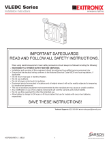
Fig. 1
Bar Hanger
Recessed
Housing Joist
Recessed Ceiling or Recessed Wall Mount
1. Position the recessed kit between the joists. (Fig. 1)
2. Align one end of the bar hangers with the bottom of the joist, then secure
temporarily by hammering in the “nail-in” tabs. Loosen the bar hanger
set screws on both sides of the recessed housing. Align the other end of
the bar hangers to the opposing joist and hammer in the “nail-in” tabs.
3. Once the bar hangers are aligned properly, permanently secure the bar
hangers by hammering in the nails.
4. With the bar hanger set screws still loose, adjust the horizontal
placement of the recessed housing between the joists by sliding along
the bar hangers. Secure by tightening the bar hanger set screws.
5. Adjust the vertical placement of the recessed housing by loosening the
vertical slot set screws, then raising or lowering the recessed housing.
The recessed housing should be positioned such that the trimplate will
be flush with the ceiling or wall when installed. Secure by tightening the
vertical slot set screws.
6. Separate the trimplate assembly from the recessed housing by
loosening the (2) screws on either end of the trimplate. The spring
hangers will keep the trimplate assembly from falling. (Fig. 2)
7. Loosen the end of the trimplate assembly closest to the wire
compartment by pinching the spring hanger and guiding its ends out
through the opening in the recessed housing. Carefully lower the
loosened end of the trimplate assembly until it is supported by the safety
cable.
8. Connect the battery/batteries to the PCB.
9. Remove the wire compartment cover and set aside.
10. Route wires into the wire compartment.
11. Make electrical connections; see Electrical Connections section.
12. Push excess wire into the wire compartment, then replace the wire
compartment cover.
13. Reposition the spring hanger into the recessed housing, then slide the
trimplate assembly back into the recessed housing and secure with the
(2) screws.
14. Connect the EXIT panel assembly to the PCB with the EXIT panel
connector, then secure by sliding into the EXIT panel slot in the trimplate
until it locks into place. Verify that the EXIT panel is properly secured by
lightly pulling the EXIT panel assembly away from the trimplate.
(Fig. 3 & 4)
NOTE: If using a single face EXIT sign, it may be necessary to change
the direction the EXIT panel is facing. This is determined when the EXIT
panel assembly is secured within the trimplate. To change the direction
of the EXIT panel, pull one end of the EXIT panel out of the EXIT panel
light bar, followed by the other end. Rotate the EXIT panel 180° then
reinstall the EXIT panel within the EXIT panel light bar.
15. Remove the protective film from the EXIT panel to complete the installation.
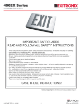
Fig. 2
Fig. 4
Fig. 3
Vertical Slot Set Screws
Bar Hanger Set Screws
Vertical Slot Set Screws
Bar Hanger Set Screws
Nail-in
Tab
Nail
EXIT Panel
Connector
Trimplate
Screw
Trimplate
EXIT Panel
EXIT Panel
Light Bar
Protective Film
Trimplate
Assembly
Safety
Cable
Spring
Hanger
Wire
Compartment
Cover EXIT Panel
Connector
Wire
Compartment
Lamp Heads
EXIT Panel
EXIT Panel
Connector
EXIT Panel
Light Bar
Protective Film
S900C Series
Installation Instructions
10070218 REV 4 - 01/21 800-533-3948 www.barronltg.com
2

Surface Ceiling or Surface Wall Mount
1. Secure the adjustable crossbar to the J-box using the (2) 8-32 x 1”
screws (supplied). Use the slotted portion of the adjustable crossbar to
mount to the J-box and position such that the portion with the threaded
holes is facing out from the J-box. (Fig. 5)
2. Punch out the desired knockouts located in the top or side of the
enclosure for ceiling or wall mounting, respectively. Insert the plastic
grommet (supplied) into the center hole.
3. Attach the canopy to the enclosure using the (2) M4 x 8mm screws
(supplied).
4. Insert the (2) plastic rivets (supplied) into the (2) unused M4 holes in the
enclosure.
5. Remove one of the enclosure end caps by removing the (4) screws and
set all aside. Slide the trimplate assembly out of the enclosure.
6. Connect the battery/batteries to the PCB.
7. Slide the trimplate assembly partially into the enclosure so that the wires
can be routed through the canopy, then route the wires through the
canopy.
8. Slide the trimplate assembly fully into the enclosure and remove the
excess slack from the wires inside the enclosure by pulling them farther
out through the canopy. Replace the end cap and secure with the
(4) screws from Step 5.
9. Make electrical connections; see Electrical Connections section.
10. Secure the fixture to the adjustable crossbar using the (2) M4 x 40mm
screws (supplied). Ensure the canopy is securely fastened against the ceiling or wall and will not rotate.
11. Connect the EXIT panel assembly to the PCB with the EXIT panel connector, then secure by sliding into the EXIT panel
slot in the trimplate until it locks into place. Verify that the EXIT panel is properly secured by lightly pulling the EXIT
panel assembly away from the trimplate. (Fig. 6)
NOTE: If using a single face EXIT sign, it may be necessary to change the direction the EXIT panel is facing. This is
determined when the EXIT panel assembly is secured within the trimplate. To change the direction of the EXIT panel,
pull one end of the EXIT panel out of the EXIT panel light bar, followed by the other end. Rotate the EXIT panel 180°
then reinstall the EXIT panel within the EXIT panel light bar.
12. Remove the protective film from the EXIT panel to complete the installation.
Remote Lamps
If the fixture is installed with the remote capable option, the fixture can support 3.6VDC 3W max. remote capabilities.
Compatible with two RL1 remote lamps (non-G2 models) or one RL1 remote lamp (G2 models).
To connect the remote head(s) to the fixture:
1. Remove the jumper, if present, and discard.
2. Connect the remote wires to the remote connector. Yellow is positive (+) and purple is negative (-).
3. Plug the remote connector into the female connector on the PCB labeled Lamp 3.
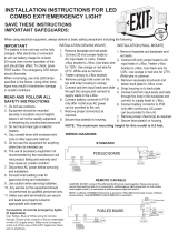
Fig. 6
Lamp Head EXIT Panel
Connector
EXIT Panel
EXIT Panel
Light Bar
Protective
Film
Fig. 5
Above: Top Mount
Right: Wall Mount
J-box
Adjustable
Crossbar
Canopy
Enclosure
End Cap
Trimplate
Assembly
J-box
J-box
S900C Series
Installation Instructions
10070218 REV 4 - 01/21 800-533-3948 www.barronltg.com
3

Electrical Connections
Make electrical connections as follows:
120VAC 277VAC
White - Common White - Common
Black - 120VAC Orange - 277VAC
Note: Cap unused wires to prevent shorting.
INPUT
LAMP 1 LAMP 2 LAMP 3
BATT 2
JK2 JK1
LED Strip
(LED, Switch)
Battery 1
Orange - 277VAC
Black - 120VAC
White - Common
Built-in
BATT 1
(Remote
Lamps)
Built-in
Battery 2
Fig. 7
S900C Series
Installation Instructions
10070218 REV 4 - 01/21 800-533-3948 www.barronltg.com
4

Self-Test/Self-Diagnostics (G2)
Operation
The purpose of this option is to provide Self-testing and Self-diagnostic capabilities to the EXIT sign. At predetermined
intervals, the EXIT sign will automatically switch into battery mode. Refer to the Self-Test Features section of this page
for timing details. The EXIT sign will also perform various Self-diagnostic tests of the EXIT sign. The circuitry continuously
monitors the operating condition of the EXIT sign and battery charging circuit. Visual signaling will alert maintenance
personnel to a fault of the EXIT sign electronics, emergency lamps, battery, and/or battery charger. Refer to the LED
Indicator section below for fault reporting details.
Self-Test Features
• The EXIT sign will automatically switch to battery mode every month for a period of 1 minute.
• The EXIT sign will automatically switch to battery mode every 6 months for a period of 30 minutes.
• The EXIT sign will automatically switch to battery mode every 12 months for a period of 90 minutes.
LED Indicator
The unit is equipped with a bi-color LED, which displays either green or red.
• A steady green LED indicates that normal AC power is being supplied to the EXIT sign.
• A flashing green LED indicates that the EXIT sign is undergoing a test.
• A blinking red LED indicates whenever the Self-diagnostic system has detected a fault condition. Refer to the chart
below when the LED is blinking red:
Test Button Features
MANUAL TEST – Pressing the test button will switch the EXIT sign into battery mode for a set amount of time. The
desired length of the test is determined by the number of times the test button is pressed.
• Pressing the test button once will switch the EXIT sign into battery mode for 30 seconds.
• Pressing the test button twice within 2 seconds will switch the EXIT sign into battery mode for 3 minutes.
• Pressing the test button 3 times within 2 seconds will switch the EXIT sign into battery mode for 30 minutes.
• Pressing the test button 4 times within 2 seconds will switch the EXIT sign into battery mode for 90 minutes.
RESET – Pressing and holding the test button for 2 seconds will reset the LED to a steady green. If multiple faults are
present, it may be necessary to repeat this procedure for each remaining fault indicated by the blinking red LED.
Use in accordance with local building codes.
Number of Blinks
1
2
3
4
5
6
7
Unit Fault
Battery Disconnected
Battery
Charge
Transfer (AC to DC)
Emergency Lamp
Remote Lamp
EXIT Panel
Corrective Action
Check Battery Connection
Replace Battery
Charger Board Circuit Fault
Transfer Function Failure
Check Lamp Connections Then Consult Factory
Check Remote Lamp Connections Then Consult Factory
Check EXIT Panel Connections Then Consult Factory
S900C Series
Installation Instructions
10070218 REV 4 - 01/21 800-533-3948 www.barronltg.com
5
/