Page is loading ...

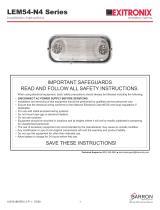
IMPORTANT SAFEGUARDS
READ AND FOLLOW ALL SAFETY INSTRUCTIONS.
· DISCONNECT AC POWER SUPPLY BEFORE SERVICING.
· Installation and servicing of this equipment should be performed by qualified service personnel only.
· Ensure that the electrical wiring conforms to the National Electrical Code NEC?and local regulations if
applicable.
· Do not mount near gas or electrical heaters.
· Suitable for damp locations. Do not use outdoors.
· Equipment should be mounted in locations and at heights where it will not be readily subjected to tampering by
unauthorized personnel.
· The use of accessory equipment not recommended by the manufacturer may cause an unsafe condition.
· Any modification or use of non-original components will void the warranty and product liability.
· Do not use this equipment for other than intended use.
·
For -WB version:
· Use caution when servicing batteries. Battery acid can cause burns to skin and eyes. If acid is spilled on skin
or in eyes, flush acid with fresh water and contact a physician immediately.
SAVE THESE INSTRUCTIONS!
Technical Support ■ (623) 580-8943 ■ [email protected]
Installation Instructions
10070267 REV 1 - 08/22
1800-533-3948 www.barronltg.com
When using electrical equipment, basic safety precautions should always be followed including the following:
CH900X Series
Allow battery to charge for 24 hours before first use.

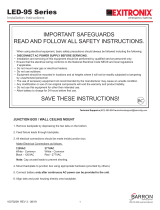
Recessed Ceiling or Recessed Wall Mount (Fig. 1-4)
1. Position the recessed kit between joists, making sure the bar
hangers are hung in the correct position. The bar hangers
should be level with the bottom of the joists. Position the
recessed kit temporarily by hammering the "nail-in" tabs on bar
hangers, then secure permanently with nails. Adjust the height
of the recessed kit vertically using adjusting slots and then
tightening all screws on adjusting slots and bar hanger bracket
to secure the adjusting bracket and bar hangers. (Fig. 1)
2. Separate the trimplate, connect the battery connectors(-WB).
3. Hang the safety rope to the module clip. (Fig. 2)
4. Disassemble the J-box cap, then route the AC line and proper
wires into the J-Box.
5. Make electrical connections; see Electrical Connections
section.
6. Push excess wire into the J-Box and tighten the J-box cap.
7. Reassemble the trimplate using the M3*15mm screws.
8. Connect the light bar connector, then insert the panel module
into the trimplate. (Fig. 3 & 4)
Fig. 1
Fig. 2
Fig. 3 - Recessed Ceiling Mount Fig. 4 - Recessed Wall Mount
Joists
Recessed Kit
Bar Hangers
Tighten screws
after positioning
Safety Rope
J-box Cap
J-box Cap
Screws
Screws
Installation Instructions
10070267 REV 1 - 08/22
2800-533-3948 www.barronltg.com
CH900X Series
9. Peel off protective film from both sides of EXIT panel ( Fig.3 )

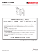
Surface Ceiling, Surface Wall, or Flag Mount (Fig. 5-7)
1. Extend unswitched 24 hour AC supply of rated voltage to J-box
(provided by others). Leave at least 18 inches of slack. Circuit should
not be energized at this time.
2. Use a screwdriver to open the front cover, then connect the battery to
the PCBA(-WB).
3. Insert the bushing into the wire access hole to prevent abrasion on the
supply wires. Bring wires through the back of the fixture.
4. Make electrical connections; see Electrical Connections section.
5. Mount to the J-box.
6. Energize the AC supply; the LED indicator will come on.
7. Assemble the EXIT panel to the enclosure using screws. If the EXIT
panel is single face, be sure the EXIT lettering is facing the right
direction.
8. Replace the front cover to finish installation.
Fig. 7 - Flag Mount
Fig. 5 - Surface Ceiling Mount
10070267 REV 1 - 08/22
3800-533-3948 www.barronltg.com
CH900X Series
Installation Instructions
Fig. 6 - Surface Wall Mount
9. Peel off protective film from both sides of EXIT panel ( Fig.6 ).

Electrical Connections
All electrical connections should be made inside the
J-box. Make electrical connections as follows:
120-277VAC
White - Common
Black - 120-277VAC
Green - Ground
Note: Cap unused wires to prevent shorting
bar. Depress the spring to release the panel, then remove the panel. (Fig. 8)
Panel Assembly (Recessed Fixtures Only)
Ensure that the wording is facing the desired direction. Insert one side of the panel
into one end of the light bar, then press the other side into place. (Fig. 9)
Maintenance and Operation
1. To test self-powered fixtures, depress the test switch. The EXIT sign will remain lit when switched to battery power(-WB).
2. Release the test switch, and the EXIT sign will operate with AC supply.
3. Servicing of any parts should be performed by qualified personnel. For replacement parts, see fixture label for proper
identification of manufactory.
4. Replace batteries according to ambient conditions(-WB). Equipment should be tested regularly in accordance with local
codes.
Wiring Diagram
Batt
Led strip
White
COMMON
Black
120~277VAC
MAIN PCBA
Battery
Exit LED Indicator
Test switch
Fig. 8
Step 1
Step 2
Fig. 9
Step 1
Step 2
Connector
10070267 REV 1 - 08/22
4800-533-3948 www.barronltg.com
Panel Disassembly (Recessed Fixtures Only)
Insert a flat screwdriver in the gap between the panel and the spring clip in the light
Wiring Diagram
Led strip
White
COMMON
Black
120~277VAC
MAIN PCBA
Exit LED
-WB Version
-LB Version
CH900X Series
Installation Instructions
/