Page is loading ...

GLS-EM-MCU
Crestron Green Light
®
Power Meter Control Unit
Installation Guide
Additional Resources
Visit the product page on the Crestron website (www.crestron.com)
for additional information and the latest rmware updates. Use a QR
reader application on your mobile device to scan the QR image.
Introduction
The Crestron
®
GLS-EM-MCU must be connected to a breaker panel, control system, and
other accessories in order to properly function. The diagram below illustrates the
installation and wiring necessary for the GLS-EM-MCU to be connected to GLS-EM-CTs
and GLS-EM-CTIs. Refer to the “Installation” and “Wiring” sections that follow for
additional details.
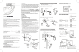
Typical Application Diagram
Installation
Attach the GLS-EM-MCU to a mounting surface using four standard screws. Once the
unit is properly secured to the mounting surface, the units must be properly wired.
WARNING: To avoid re, shock, or death, turn off the power at the circuit breaker or
fuse and test that the power is off before wiring!
NOTES: Observe the following points:
• Install and use this prodct in accordance with appropriate electrical codes and
regulations.
• A licensed electrician should install this product.
NOTE: Before using the GLS-EM-MCU, ensure the device is using the latest rmware.
Check for the latest rmware for the GLS-EM-MCU at www.crestron.com/rmware.
Load rmware onto the device using Crestron Toolbox™ software.
Wire Third-Party Pulse Monitors
Attach third-party pulse monitors to the ports labeled PULSE INPUTS 1 through 4.
NOTE: The pulse inputs have 10 kΩ, 3.3 Vdc, internal pull-ups .
Connect to Control System
The GLS-EM-MCU connects to a control system via an Ethnert LAN. Connect an
Ethernet cable to the LAN port of the GLS-EM-MCU and the other end to the LAN or
directly to a control system.
8-Wire bus connects
to additional
GLS-EM-CTI devices
for expansion of
system.
8-Wire bus connecting GLS-EM-MCU to
GLS-EM-CTI.
This connection uses Class 1 wiring and
must be piped.
Split-core GLS-EM-CT
connects to GLS-EM-MCU.
Split-core GLS-EM-CT
Solid-core
GLS-EM-CT
Solid-core GLS-EM-CT
connects to GLS-EM-CTI.
Third-party
pulse monitors.
class 2 wiring.
Wiring
The information that follows describes the necessary wiring for the GLS-EM-MCU to be connected to GLS-EM-CTs and GLS-EM-CTIs. It also describes the wiring to connect third-party
pulse monitors.
NOTE: To prevent wire noise, make sure that the maximum distance between a GLS-EM-MCU or GLS-EM-CTI and a GLS-EM-CT does not exceed 50 feet (~16 meters).
Run Power
Run power from the line feeds of the breaker panel and connect to LINE 1, LINE2, and LINE 3 ports on the GLS-EM-MCU. Ensure that the current transformer connected to the rst feed is
connected to CT1 and the line power is connected to LINE 1. Repeat using the second and third feed entering the breaker panel.
Connect the neutral connector on the breaker panel to the neutral (NEUT) port on the GLS-EM-MCU. Refer to the “Typical Application Drawing” for wiring details.
Wire GLS-EM-CT Devices
Connect the GLS-EM-CT devices to the CT1, CT2 and CT3 ports on the GLS-EM-MCU. Ensure that the white wire is connected to the port labeled WHT and the black wire is connected
to the port labeled BLK. The appropriate CT1, CT2, or CT3 LED illuminates if properly wired. If the device is incorrectly wired, the respective LED blinks. Refer to the illustration that follows
for details.
Wire GLS-EM-CTI Bus and Passthrough (Optional)
Use the supplied bus wire to connect the BRANCH CIRCUIT MONITORS port of the GLS-EM-MCU to the port of the GLS-EM-CTI. Ensure that the wires are connected to the proper
terminals between the two units. If additional GLS-EM-CTIs are to be used, use the bus wire to connect up to four GLS-EM-CTI devices.

Crestron Electronics, Inc. Installation Guide - DOC. 7295B
15 Volvo Drive Rockleigh, NJ 07647 (2032459)
Tel: 888.CRESTRON 08.16
Fax: 201.767.7576 Specications subject to
www.crestron.com change without notice.
The product warranty can be found at www.crestron.com/warranty.
The specic patents that cover Crestron products are listed at patents.crestron.com.
Certain Crestron products contain open source software. For specic information, please visit
www.crestron.com/opensource.
Crestron, the Crestron logo, Crestron Green Light, and Crestron Toolbox are either trademarks or
registered trademarks of Crestron Electronics, Inc. in the United States and/or other countries. Other
trademarks, registered trademarks, and trade names may be used in this document to refer to either the
entities claiming the marks and names or their products. Crestron disclaims any proprietary interest in the
marks and names of others. Crestron is not responsible for errors in typography or photography.
This document was written by the Technical Publications department at Crestron.
©2016 Crestron Electronics, Inc.
/