Crestron CLS-C6RF Installation guide

Type
Installation guide

This manual is also suitable for

CLS-C6MRF/CLS-C6RF/CLSI-C6MRF/CLSI-C6RF
iLux
®
Integrated Lighting System
Installation Guide
Installation
The following tools and hardware are required for installation:
4-gang electrical box (not supplied) that is a minimum of 3-1/2 in (89 mm) deep
Phillips torque screwdriver (not supplied)
Four 7/8 in (~22 mm) pan head Phillips screws (supplied)
If the planned conguration includes connection to shade controllers, keypads, or a
Crestron control system, the following items are also required:
• Cresnet
®
network cable(s) (not supplied)
Terminal block connector(s) (two supplied)
NOTE: For detailed conguration options, refer to the CLS(I)-C6/C6M and
CLS(I)-C6RF/C6MRF Reference Guide (Doc. 6347) at www.crestron.com/manuals.
Check that any required Cresnet wiring has been installed and veried. Then, use the
following procedure to install the CLS-C6RF.
1. Feed the wires (power line from the distribution panel, load wires, plus any required
Cresnet cables) through the holes in the electrical box.
2. Hold the rear of the CLS-C6RF unit and remove the front panel and cover assembly
by carefully pulling out and up from the bottom edge.
CLS-C6MRF Installation
Description
The iLux units are complete integrated wall-mounted lighting systems that can function
as stand-alone devices or as part of a total Crestron
®
solution via the inNET™ network.
The domestic units, CLS-C6RF and CLS-C6MRF, and international units, CLSI-C6RF
and CLSI-C6MRF, are functionally identical except that the CLS-C6MRF and
CLSI-C6MRF include a built-in motion sensor. The CLS-C6RF and CLS-C6MRF operate
at 100 to 127 Vac, and the CLSI-C6RF and CLSI-C6MRF operate at 220 to 240 Vac. For
simplicity within this guide, the term “CLS-C6RF” is used except where noted.
CLS-C6RF Specications
Additional Resources
Visit the product page on the Crestron website (www.crestron.com)
for additional information and the latest rmware updates. Use a QR
reader application on your mobile device to scan the QR image.
Important Notes
WARNING: To avoid re, shock, or death, turn off power at circuit breaker or fuse and
test that power is off before wiring!
WARNING: New installations should be checked for short circuits prior to installing a
CLS-C6RF. With the power off, close the circuit, and then restore power. If the lights
do not work, or a breaker trips, check and correct the wiring or xture (if necessary).
Install the CLS-C6RF only when the short is no longer present. The warranty is void if
the CLS-C6RF is installed and operated with a shorted load.
CAUTION: TO REDUCE THE RISK OF OVERHEATING AND POSSIBLE DAMAGE TO
OTHER EQUIPMENT, DO NOT INSTALL TO CONTROL A RECEPTACLE, A
MOTOR-OPERATED APPLIANCE OR A TRANSFORMER-SUPPLIED APPLIANCE.
ATTENTION: GRADATEURS COMMANDANT UN BALLAST-AFIN DE RÉDUIRE LE
RISQUE DE SURCHAUFFE ET LA POSSIBILITÉ D’ENDOMMAGEMENT À D’AUTRES
MATÉRIELS, NE PAS INSTALLER POUR COMMANDER UNE PRISE, UN APPAREIL
OPÉRÉ DE MOTEUR OU UN APPAREIL ALIMENTÉ PAR UN TRANSFORMATEUR.
4-Gang
electrical box
Mounting
screws (4)
Front cover assembly
Control panel
overlay
1. If a unit is fed from an arc fault circuit interrupter, the maximum total load is 1,000 W/VA to avoid nuisance tripping.
2. For a list of compatible ballasts, visit www.crestron.com/lightingcompatibility.
Shade
controller
Keypad
GLS-SIM
Occupancy
sensor
CLS-C6RF
Cresnet (24, Y, Z, G—Local devices)
Cresnet
(G,Y, Z)
Only
Lighting
loads
Shade
controller
Shade
controller
Shade
controller
Photocell
Shade
controller
Touch
screen
Power
supply
CSA-PWS225/450
power supply
Shade
CSA-PWS40
power supply
CLS-C6RF
Lighting loads
Cresnet (24, Y, Z, G—Local devices)
Shade
3. Remove the control panel overlay from the CLS-C6RF, which is held in place by
small tabs and lifts off, to reveal the upper mounting screw holes.
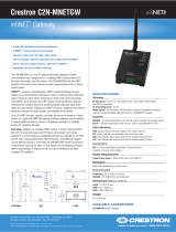
4. Refer to the wiring diagram for the ac wiring. All wires that are to be inserted in the
screw terminals should be stripped 7/16 in (~11 mm), and screws should be
tightened to between 8 and 10 in.-lbs. (0.90 to 1.13 Nm). The maximum wire size is
12 AWG (3 mm
2
).
5. Connect each load wire to the corresponding LOAD terminals on the CLS-C6RF,
connect the power line hot wire from the circuit breaker to the HOT terminal on the
CLS-C6RF, connect all neutral wires to the NEUTRAL terminal on the CLS-C6RF,
and connect all ground wires to the ground terminal on the unit.
6. If Cresnet cabling is part of the installation, attach the supplied terminal block
connector(s) to the Cresnet cable(s) and plug into the appropriate port(s) on the
CLS-C6RF. Make certain that there is a minimum 1/4 in (~6 mm) separation
between the Class 2 Cresnet wiring and the Class 1 ac wiring.
NOTE: Use a 15 or 20 A circuit breaker depending on installation requirements.
Refer to specications for load rating details.
NOTE: CLS-EXP expansion modules can be used in place of any or all loads
shown above. Refer to expansion module documentation for wiring details.
SPECIFICATION DETAILS
Power Requirements
Domestic
International
Line Power, 100 to 127 Vac, 50/60 Hz
Line Power, 220 to 240 Vac, 50/60 Hz
Domestic Load Ratings
1
Max load per channel
Min load per channel
Max load per unit
800 W/VA (6.6 A at 120 Vac), expandable via
CLS-EXP expansion modules (sold separately)
15 W/VA (0.125 A at 120 Vac)
1,920 W/VA (16 A at 120 Vac)
International Load Ratings
1
Max load per channel
Min load per channel
Max load per unit
800 W/VA
(3.5 A at 230 Vac), expandable via
CLS-EXP expansion modules (sold separately)
25 W/VA (0.108 A at 230 Vac)
2,200 W/VA (10 A at 220 Vac)
2,300 W/VA (10 A at 230 Vac)
2,400 W/VA (10 A at 240 Vac)
Load Types
Dim LED
2
, Incandescent, Magnetic Low-voltage,
Neon/Cold Cathode, 2-Wire Dimmable Fluorescent,
and Non-Dim Lighting;
Switch Electronic Low-voltage, 3- and 4-Wire Fluorescent,
High-Inrush Switching, and 277 V via CLS-EXP series
expansion modules (sold separately)
Cresnet
®
Power for
Local Devices
10 W maximum
External power supply sold separately
Environmental
Temperature
Humidity
32° to 104 °F (0° to 40 °C)
10% to 90% RH (noncondensing)
Enclosure Mounts in a 4-gang electrical box, 3-1/2 in (89 mm)
deep minimum
7. Carefully tuck all of the wires into the electrical box and, using the four 7/8 in
(~22 mm) Phillips screws supplied, fasten the CLS-C6RF to the electrical box.
8. Reattach the control panel overlay to the front panel by inserting the four tabs into
the slots on the CLS-C6RF, and install the hinged front cover assembly by lining it
up at the top and pressing the bottom edge until the cover snaps into position.
Adding External Power Supplies
Additional power supplies are required to support more than four keypads or shade
controllers on the local devices network. Also, each C2N-SDC-DC, CSM-QMTDC, and
CSC-DCCN shade controller requires its own additional power supply. The diagrams
below illustrate a scenario where an external power supply is required to add a shade
controller and other devices to a network that already contains four shade controllers.
The actual number of external power supplies required depends on the system
conguration. The illustrations show a variety of installation congurations.
NOTE: Always use Crestron certied wire.
Adding External Power Supply for C2N-SDC-DC Controlled Shades
Adding External Power Supply for CSM-QMTDC and CSC-DCCN Controlled Shades
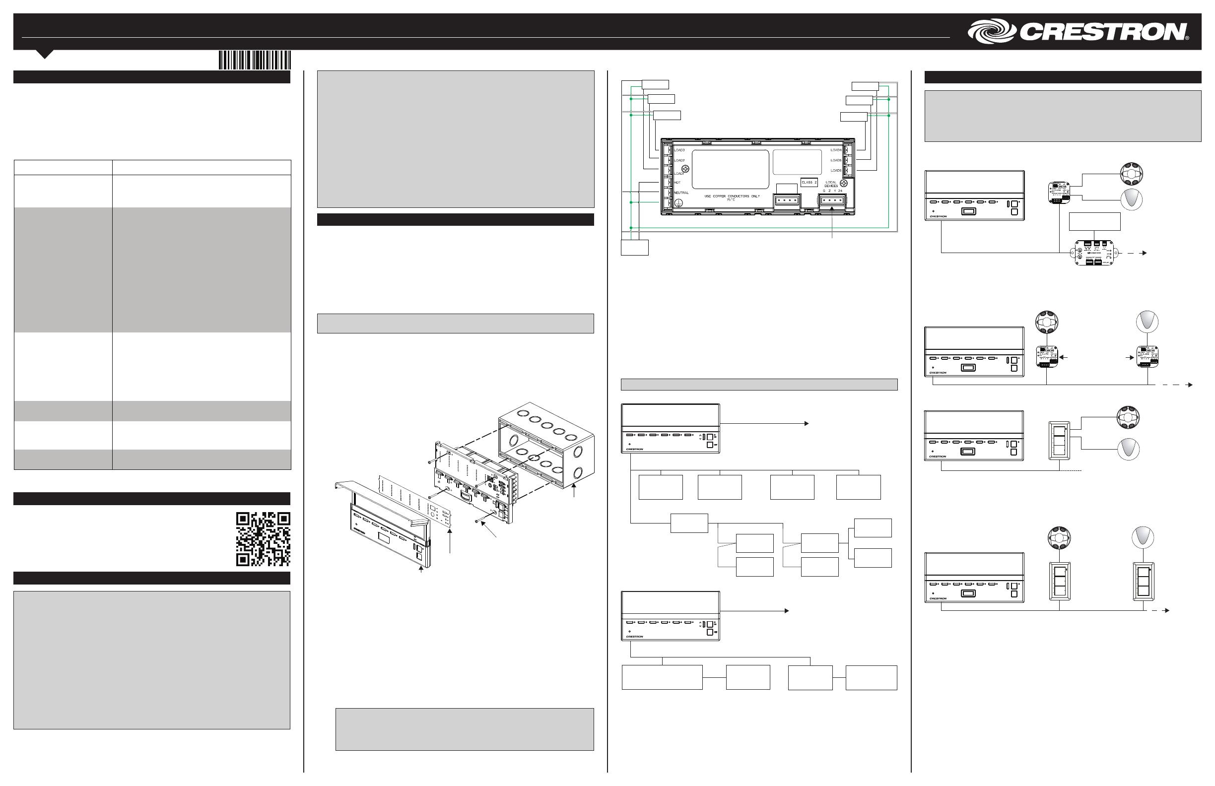
Wiring Occupancy Sensors and Photocells
NOTE: Before using the CLS-C6RF, ensure the device is using the latest rmware.
Check for the latest rmware for the CLS-C6RF at www.crestron.com/rmware. Load
the rmware onto the device using Crestron Toolbox™ software.
NOTE: Refer to the CLS(I)-C6/C6M and CLS(I)-C6RF/C6MRF iLux Integrated Lighting
System Reference Guide (Doc. 6347) for details on supported devices.
CLS-C6MRF with One GLS-SIM and One C2N-IO
CLS-C6MRF with Two GLS-SIM Units
CLS-C6MRF with One C2N-CBD-P Keypad
CLS-C6MRF with Two C2N-CBD-P Keypads
NOTE: Observe the following points:
Codes: Install in accordance with all local and national electrical codes.
Installation: A licensed electrician must install the CLS-C6RF.
Wiring: Use copper wire only. For supply connections, use wire rated for at least
75 °C. The CLS-C6RF requires a neutral wire connection for operation.
Lamp Type: For use with permanently installed LED, incandescent, magnetic low
voltage, neon/cold cathode, 2-wire dimmable uorescent, and non-dim lighting
only, electronic low voltage, 3- and 4-wire uorescent, high-inrush switching, and
277 V via CLS-EXP Series expansion modules (sold separately).
Temperature: Use where temperatures are from 32° to 104 °F (0° to 40 °C).
Electrical Boxes: The CLS-C6RF mounts in standard, 4-gang electrical boxes. For
installation, Crestron recommends using 3-1/2 in (89 mm) deep electrical boxes.
Spacing: If mounting one device above another, leave at least 4-1/2 in (115 mm)
vertical space between them.
Standard Cresnet wiring
Load 3
Load 2
Load 1
Hot
Neutral
Ground
Circuit
breaker
Load 5
Load 6
Load 4
NOT
USED
CLS-C6MRF Wiring
Cresnet (local devices)
GLS-O
Occupancy sensor
(input 1 only)
GLS-SIM
(Cresnet ID set to
C0 or C1)
GLS-LOL
(input 2 only)
Cresnet (local devices)
C2N-IO
GLS-O
occupancy sensor
(input 1 only)
GLS-SIM (Cresnet ID
set to C0 or C1)
GLS-LOL
(input 2 only)
RS-232 to
control system
Cresnet (local devices)
C2N-CBD-P
keypad
GLS-O
occupancy sensor
(input 1 only)
GLS-LOL
(input 2 only)
Cresnet (local devices)
C2N-CBD-P
Keypad
GLS-O
occupancy sensor
(input 1 only)
GLS-LOL
(input 2 only)
TROUBLE POSSIBLE CAUSE(S) CORRECTIVE ACTION
The unit does not
function.
The unit is not
receiving line power.
Verify that the unit is properly
connected to the power line and
that the circuit breaker is closed.
The loads turn on and
off but do not dim.
The loads are not
connected.
Verify that the loads are
operational and that they are
connected to the iLux unit.
The incorrect load
type or load types are
set.
Correct the load type settings.
The lights icker at
low levels.
The incorrect low-end
limit is set.
Change the low-end limit setting.
These products are Listed to applicable UL
®
Standards and requirements by Underwriters
Laboratories Inc.
Ces produits sont énumérés aux normes applicables et les exigences UL par Underwriters
Laboratories Inc.
As of the date of manufacture, these devices have been tested and found to comply with
specications for CE marking.
Federal Communications Commission (FCC) Compliance Statement
CAUTION: Changes or modications not expressly approved by the manufacturer responsible for
compliance could void the user’s authority to operate the equipment.
Crestron Electronics, Inc. Installation Guide - DOC. 6416E
15 Volvo Drive Rockleigh, NJ 07647 (2013966)
Tel: 888.CRESTRON 12.16
Fax: 201.767.7576 Specications subject to
www.crestron.com change without notice.
NOTE: This equipment has been tested and found to comply with the limits for a Class B digital device,
pursuant to part 15 of the FCC Rules. These limits are designed to provide reasonable protection against
harmful interference in a residential installation. This equipment generates, uses and can radiate radio
frequency energy and, if not installed and used in accordance with the instructions, may cause harmful
interference to radio communications. However, there is no guarantee that interference will not occur in a
particular installation. If this equipment does cause harmful interference to radio or television reception,
which can be determined by turning the equipment off and on, the user is encouraged to try to correct the
interference by one or more of the following measures:
Reorient or relocate the receiving antenna.
Increase the separation between the equipment and receiver.
Connect the equipment into an outlet on a circuit different from that to which the receiver is
connected.
Consult the dealer or an experienced radio/TV technician for help.
Industry Canada (IC) Compliance Statement
Operation is subject to the following two conditions:
1. This device may not cause interference, and
2. This device must accept any interference, including interference that may cause undesired operation
of the device.
To satisfy RF exposure requirements, this device and its antenna must operate with a separation distance
of at least 20 centimeters from all persons and must not be colocated or operating in conjunction with any
other antenna or transmitter.
The product warranty can be found at www.crestron.com/warranty.
The specic patents that cover Crestron products are listed at patents.crestron.com.
Certain Crestron products contain open source software. For specic information, please visit
www.crestron.com/opensource.
Installation Congurations
The following illustrations describe ve installation congurations.
Method 1: A Stand-Alone CLS-C6RF (Most Common Use)
Method 2: A Primary CLS-C6RF with Multiple Secondary CLS-C6RF Units
Method 3: A CLS-C6RF with a Control System Communicating to the CLS-C6RF via
C2N-MNETGW Gateway Using inNET (Method 1 Variation)
Method 5: A Control System with Multiple CLS-C6RF Units on the Main inNET Network
Method 1 is the simplest way to control up to six lighting loads and six shade control
groups. No control system is required.
Method 2 is used in a large room with more than six lighting loads and shade groups. No
control system is required.
Scene recall and master dimmers affect the entire room. The user can still adjust each
circuit individually. For details on room combining, refer to the CLS(I)-C6/C6M and
CLS(I)-C6RF/C6MRF iLux Integrated Lighting System Reference Guide (Doc. 6347).
In Method 3, the control system can control and monitor operation of the lighting system
and can trigger lighting scenes from touch screens, RF wireless remotes, computers, or
a real-time clock. Buttons on the lighting system can control other functions.
The CLS-C6RF still operates on its own if the control system is not running.
In Method 5, the control system can monitor and control the lighting in multiple
independent rooms. The rooms can be combined and arranged under program control.
This method includes all of the features of the other congurations.
Each individual CLS-C6RF can operate on its own if the control system is not running.
Supported Devices
The following table lists devices and power requirements supported by CLS-C6RF units.
Supported Devices and Power Requirements
Testing
The following illustration shows the front panel of the CLS-C6RF and the controls used
during installation.
Front Panel Controls and Indicators
Troubleshooting
The following table provides corrective actions for possible trouble situations. If further
assistance is required, please contact a Crestron customer service representative. For
details on setting load types and low-end limits, refer to the CLS(I)-C6/C6M and
CLS(I)-C6RF/C6MRF iLux Integrated Lighting System Reference Guide (Doc. 6347).
CLS-C6RF Installation Troubleshooting
Verify the basic installation and wiring connections as follows:
1. Press the Lights button to enable manual light control, and press the right side and
the left side of each of the function buttons to increase and decrease the lighting
level of those loads. Verify that the intended loads and corresponding LED bar
graphs respond appropriately.
2. Press the OFF button to turn off all loads. The loads ramp down to off while the
two-digit display counts down to off (blank). Two seconds after all lights have
turned off, the unit’s master air-gap relay opens, making it safe to service the
lighting installations.
CLS-C6RF
Cresnet (local devices)
Optional Cresnet devices
Lighting loads or CLS-EXP
expander modules
Lighting loads or CLS-EXP
expander modules
Cresnet (local devices)
Optional
Cresnet
devices
CLS-C6RF
Cresnet
(control system)
Lighting
loads
Optional
Cresnet
devices
Up to 8
Cresnet
(control system)
Lighting
loads
Cresnet (Local Devices) Cresnet (local devices)
Optional
Cresnet
devices
CLS-C6RF
CLS-C6RF
Cresnet
Control system
C2N-MNETGW
inNET
(local devices)
Optional
Cresnet
devices
Cresnet (local devices)
Optional
Cresnet
devices
Lighting loads
or CLS-EXP
expander modules
CLS-C6RF
Method 4: A CLS-C6RF in a Large Room with a Control System Communicating to the
CLS-C6RF via C2N-MNETGW Gateway Using inNET (Method 3 Variation)
Cresnet
(Local devices)
Control system
C2N-MNETGW
inNET
Optional
Cresnet
devices
Lighting loads
or CLS-EXP
expander modules
Cresnet
(control system)
Optional
Cresnet
devices
Cresnet
(control system)
Lighting
loads
Up to 8
Lighting
loads
Crestnet (local devices)
Optional
Cresnet
devices
Optional
Cresnet
devices
CLS-C6RF
CLS-C6RF
CLS-C6RF
Cresnet
Optional
Cresnet
devices
(local devices)
inNET
Lighting
loads
Up to 5
Optional
Cresnet
devices
Crestnet (local devices) Crestnet (local devices)
Lighting
loads
Optional
Cresnet
devices
Control system
C2N-MNETGW
CLS-C6RF CLS-C6RF
2-Digit
display
LED
bar graphics
Lights
button
Function buttons
^
^
Scene 1 Scene 2 S cene 3 S cene 4 S c ene 5 S c ene 6
^
^
M in
Sec
Ligh ts
Shade s
Save
C an cel
1 2 3 4 5 6
ON
OFF
This document was written by the Technical Publications department at Crestron.
©2016 Crestron Electronics, Inc.
Crestron, the Crestron logo, Cameo, Cresnet, Crestron Toolbox, iLux, inNET, and QMT are either
trademarks or registered trademarks of Crestron Electronics, Inc. in the United States and/or other
countries. Somfy is either a trademark or registered trademark of Somfy Systems, Inc. in the United
States and/or other countries. UL and the UL logo are either trademarks or registered trademarks of
Underwriters Laboratories, Inc. in the United States and/or other countries. Other trademarks,
registered trademarks, and trade names may be used in this document to refer to either the entities
claiming the marks and names or their products. Crestron disclaims any proprietary interest in the
marks and names of others. Crestron is not responsible for errors in typography or photography.
NAME DESCRIPTION CRESNET POWER
FACTOR (W)
MAX
QTY
C2N-DB6 6-Button Keypad 3 W 16
C2N-DB8 8-Button Keypad 3 W 16
C2N-DB12 12-Button Keypad 3 W 16
C2N-CBD/CBF
(All Models)
Cameo
®
Keypad 0.5 W 16
C2NI-CB &
INETI-CB
Cameo Keypad
(International)
0.5 W 16
C2N-IO Control Port Expansion Module 1 W 1
C2N-SDC Shade and Drape Controller,
120 Vac
3 W 16
C2N-SDC-DC Shade and Drape Controller,
24 Vdc
Up to 33 W 16
C2N-SSC-2 Somfy
®
Shade Controller 1 W 16
CNX-B2 2-Button Keypad 3 W 16
CNX-B4 4-Button Keypad 3 W 16
CNX-B6 6-Button Keypad 3 W 16
CNX-B8 8-Button Keypad 3 W 16
CNX-B12 12-Button Keypad 3 W 16
CSC-ACCN Cresnet
®
Interface to Somfy
®
ST50 ILT2 Motor
N/A 16
CSC-DCCN Cresnet
®
Interface to Crestron
®
CSM-QMT30 Shades
N/A 16
CSC-DRPCN Drapery Track Interface N/A 16
CSM-QMTDC-
256-2-CN
Digital QMT
®
Shade Motor for
21 in Roller Shades and Larger,
2 Nm, Cresnet
®
Network
36 W 16
CSM-QMTDC-
163-1-CN
Digital QMT
®
Shade Motor for
QMT3 Series, Cresnet
®
Network
42.5 W
16
CSM-QMTDC-
250-2-CN
Digital QMT
®
Shade Motor for
QMT5 Series, 2 Nm, Cresnet
®
Network
36 W
16
CSM-QMTDC-
250-4-CN
Digital QMT
®
Shade Motor for
QMT5 Series, 4 Nm, Cresnet
®
Network
42.5 W
16
CSM-QMTDC-
DRP-3-CN
Digital QMT
®
Drapery Motor for
CSS-DRAPERY, Cresnet
®
Network
42.5 W
16
GLS-SIM Sensor Integration Module
1 W plus
attached
sensor
wattage
Partitions
36
Occupancy
Sensing
2
BMS
Integration
4
GLS-ODT &
GLS-OIR
Series
Occupancy Sensors 1 W 2
TPS-4L 3.6 in Wall-Mount Touch Screen 5 W 2
TPS-6L 5.7 in Wall-Mount Touch Screen 15 W 2
  • Page 1 1
  • Page 2 2

Crestron CLS-C6RF Installation guide

Type
Installation guide
This manual is also suitable for

Ask a question and I''ll find the answer in the document

Finding information in a document is now easier with AI