Page is loading ...

Regulatory Compliance
CONFORMS TO UL STD 61010-1; CERTIFIED TO CSA STD C22.2 NO. 61010-1
ETL listed for compliance to UL 61010-1 Issued:2004/07/12 Ed:2 Rev:2008/10/28 UL
Standard for Safety Electrical Equipment For Measurement, Control, and Laboratory Use;
Part 1: General Requirements, and CAN/CSAC22.2#61010-1 Issued:2004/07/01 Ed:2
Standard for Safety Electrical Equipment For Measurement, Control, and Laboratory Use;
Part 1: General Requirements.
This product has been tested to the requirements of CAN/CSA-C22.2 No. 61010-1, 2nd
edition, including Amendment 1, or a later version of the same standard incorporating the
same level of testing requirements.
Ce produit a été testé en accord avec les exigences de CAN/CSA-C22.2 No. 61010-1,
2eme Edition, ci-inclus l'amendement 1, ou un version ultérieur du meme règlement
incorporant les memes conditions d'essai.
Crestron Electronics, Inc. Installation Guide - DOC. 7296D
15 Volvo Drive Rockleigh, NJ 07647 (2032460)
Tel: 888.CRESTRON 05.14
Fax: 201.767.7576 Specifications subject to
www.crestron.com change without notice.
Further Inquiries
To locate specific information or resolve questions after reviewing this guide, contact Crestron's True Blue Support at
1-888-CRESTRON [1-888-273-7876] or, for assistance within a particular geographic region, refer to the listing of
Crestron worldwide offices at www.crestron.com/offices.
To post a question about Crestron products, log onto Crestron’s Online Help at www.crestron.com/onlinehelp.
First-time users must establish a user account to fully benefit from all available features.
Future Updates
As Crestron improves functions, adds new features, and extends the capabilities of the GLS-EM-CT, additional
information may be made available as manual updates. These updates are solely electronic and serve as
intermediary supplements prior to the release of a complete technical documentation revision.
Check the Crestron website periodically for manual update availability and its relevance. Updates are identified as
an “Addendum” in the Download column.
WARNING: To avoid fire, shock, or death; turn off power at circuit breaker or fuse and test that power is off before
wiring!
NOTES: Observe the following points.
• To be installed and/or used in accordance with appropriate electrical codes and regulations.
• This product should be installed by a qualified electrician.
PREPARING AND CONNECTING WIRES
Strip the ends of the wires approximately 1/4 in (6 mm). Use care to avoid nicking the conductors. Twist together
the ends of the wires that share a connection. Apply solder only to the ends of the twisted wires. Avoid tinning too
far up the wires or the end becomes brittle.
Crestron GLS-EM-CT
Crestron Green Light
®
Current Transformers
Installation Guide
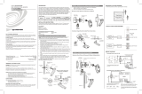
Dimensional Drawing for Solid Core
Dimensional Drawing for Split Core
3.26 in
(83 mm)
3.35 in
(86 mm)
1.07 in
(27 mm)
1.26 in
(32 mm)
Barcode and
Characterization
Label
Black
Lead
Wire
White
Lead
Wire
The current transformer has two 8 foot
(~2.4 meter) twisted pair lead wires.
Lead wires can be trimmed as needed.
1.39 in
(36 mm)
0.71 in
(18 mm)
0.94 in
(24 mm)
1.40 in
(36 mm)
0.56 in
(15 mm)
Ø 0.64 in
(17 mm)
Label
White
Black
Barcode and
Characterization
Label
The current
transformer has two 8
foot (~2.4 meter)
twisted pair lead wires.
Lead wires can be
trimmed as needed.
INTRODUCTION
Current transformers are vital to metering power. Crestron
®
offers various split-core models
that work with 600, 400, and 200 amp feeds; these devices clamp around main feeds.
Solid-core models exist for 50 and 20 amp circuits; the wire must be routed through the
closed loop of the core.

RETURN AND WARRANTY POLICIES
Merchandise Returns / Repair Service
1. No merchandise may be returned for credit, exchange or service without prior authorization from
Crestron. To obtain warranty service for Crestron products, contact an authorized Crestron dealer.
Only authorized Crestron dealers may contact the factory and request an RMA (Return
Merchandise Authorization) number. Enclose a note specifying the nature of the problem, name
and phone number of contact person, RMA number and return address.
2. Products may be returned for credit, exchange or service with a Crestron Return Merchandise
Authorization (RMA) number. Authorized returns must be shipped freight prepaid to Crestron,
6 Volvo Drive, Rockleigh, N.J. or its authorized subsidiaries, with RMA number clearly marked on
the outside of all cartons. Shipments arriving freight collect or without an RMA number shall be
subject to refusal. Crestron reserves the right in its sole and absolute discretion to charge a 15%
restocking fee plus shipping costs on any products returned with an RMA.
3. Return freight charges following repair of items under warranty shall be paid by Crestron, shipping
by standard ground carrier. In the event repairs are found to be non-warranty, return freight costs
shall be paid by the purchaser.
Crestron Limited Warranty
Crestron Electronics, Inc. warrants its products to be free from manufacturing defects in materials and
workmanship under normal use for a period of three (3) years from the date of purchase from Crestron,
with the following exceptions: disk drives and any other moving or rotating mechanical parts, pan/tilt heads
and power supplies are covered for a period of one (1) year; touch screen display and overlay components
are covered for 90 days; batteries and incandescent lamps are not covered.
This warranty extends to products purchased directly from Crestron or an authorized Crestron dealer.
Purchasers should inquire of the dealer regarding the nature and extent of the dealer's warranty, if any.
Crestron shall not be liable to honor the terms of this warranty if the product has been used in any
application other than that for which it was intended or if it has been subjected to misuse, accidental
damage, modification or improper installation procedures. Furthermore, this warranty does not cover any
product that has had the serial number altered, defaced or removed.
This warranty shall be the sole and exclusive remedy to the original purchaser. In no event shall Crestron
be liable for incidental or consequential damages of any kind (property or economic damages inclusive)
arising from the sale or use of this equipment. Crestron is not liable for any claim made by a third party or
made by the purchaser for a third party.
Crestron shall, at its option, repair or replace any product found defective, without charge for parts or
labor. Repaired or replaced equipment and parts supplied under this warranty shall be covered only by the
unexpired portion of the warranty.
Except as expressly set forth in this warranty, Crestron makes no other warranties, expressed or implied,
nor authorizes any other party to offer any warranty, including any implied warranties of merchantability or
fitness for a particular purpose. Any implied warranties that may be imposed by law are limited to the
terms of this limited warranty. This warranty statement supersedes all previous warranties.
The specific patents that cover Crestron products are listed at patents.crestron.com.
Crestron, the Crestron logo, and Crestron Green Light are either trademarks or registered trademarks
of Crestron Electronics, Inc. in the United States and/or other countries. Other trademarks, registered
trademarks, and trade names may be used in this document to refer to either the entities claiming the
marks and names or their products. Crestron disclaims any proprietary interest in the marks and names
of others. Crestron is not responsible for errors in typography or photography.
This document was written by the Technical Publications department at Crestron.
©2014 Crestron Electronics, Inc.
INSTALLATION
CAUTION: All work should be performed by a qualified electricial using proper safety
equipment.
NOTE: If the GLS-EM-CT current transformers are used in a manner other than
described in this document, the protection provided by the current transformer may be
impaired.
NOTE: To prevent wire noise, the maximum distance between a GLS-EM-MCU or
GLS-EM-CTI and a GLS-EM-CT should not exceed 50 feet (~15.3 meters).
Installing Main Feed Current Transformer
1. Locate and turn off feed to distribution panel.
2. Open split-core current transformer by pulling on removable leg.
3. Connect current transformer around conductor to be monitored. Ensure that the label
THIS SIDE TOWARDS SOURCE faces away from the main lug feeding the panel.
4. If necessary, repeat steps 2 and 3 for additional current transformers.
5. Route the current transformer output leads through appropriate conduit as required.
6. Connect the current transformer wires to the correct terminal position on the
GLS-EM-MCU.
NOTE: The current transformer wires must be connected to an input with the same
phase designation as the feed it is monitoring.
7. Apply power to panel when installation of all components is complete and proceed
with system setup and testing. For wiring details, refer to the GLS-EM-MCU
Installation Guide (Doc. 7295) at www.crestron.com/manuals.
Installing Branch Current Transformer
1. Locate and turn off circuit breaker of branch feed to be monitored.
2. Remove branch feed line from circuit breaker.
3. Pass branch feed line through the solid-core current transformer center. Make sure
that the label THIS SIDE TOWARDS SOURCE faces the circuit breaker.
4. If necessary, repeat steps 2 and 3 for additional branch feed transformers.
5. Route current transformer output leads through appropriate conduit as required.
6. Connect the current transformer wires to the correct terminal position on the
GLS-EM-CTI.
NOTE: The current transformer wires must be connected to an input with the same
phase designation as the breaker it is monitoring. Terminals on GLS-EM-CTI
alternate phasing (A, B, A, B for 2-phase and A, B, C, A, B, C for 3-phase systems).
7. Turn circuit breaker on when installation of all components is complete and proceed
with system setup and testing. For wiring details, refer to the GLS-EM-MCU
Installation Guide (Doc. 7295).
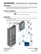
Installation Diagram for GLS-EM-CT Devices
A B C N
GLS-EM-MCU
GLS-EM-CTI
To Additional
GLS-EM-CTIs
GLS-EM-CT
GLS-EM-CT
Breaker Panel
L1
L2
L3
/