Page is loading ...

1
IMPORTANT:
Go to for the
complete user guide, installation
instructions, and specifications.
www.extron.com
EWB 112 • Installation Guide
Overview
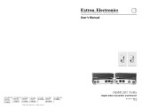
The Extron EWB 112 is a two-gang external wall box. It provides
complete compatibility in t and nish with Extron devices such
as the MLC Plus 100 and DTP T UWP 4K 232 D. Figure 1 shows
a typical application.
This guide provides basic instructions for installation of either
model by an experienced installer.
Equipment Needed but not Provided
• Stud detector • Cable raceway (optional)
• Electric drill • Fasteners for wall mounting
(see the table under gure 2,
below)
• Screw driver
• Small wire cutters
ON
PC
VIDEO
MUTE
OFF
LAPTOP
ON
P
C
VI
DEO
M
UTE
OFF
LAP
TO
P
MLC Plus 100
EWB 112
Figure 1. Typical Application for EWB 110 Series Wall Box
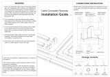
EWB 112 Mounting Holes
The EWB 112 is mounted directly onto the wall. Use the mounting holes shown in gure 2.
#6
M3
6-32
e
AA
C
C
B
B
E
E
D
D
F
F
Figure 2. EWB 112 Mounting Holes
A
Device mounting holes (4) — use #6-32 screws.
B
Primary wall mounting holes (4) — use screws and fasteners that are appropriate for the wall.
Wall Type Fastener Minimum Size
Fastener
Quantity Drill Bit Size Notes
Dry wall Toggle bolts 3/16 inch at least 2 1/2 inch Wall thickness 3/8 inch minimum
Solid wood Wood screws #6 at least 2 1/8 inch Wall thickness 3/8 inch minimum
Masonry Masonry screws 3/16 inch at least 2 5/32 inch masonry bit Do not mount to masonry joints.
C
Additional wall mounting holes (2) — These holes should be used only if the primary wall mounting holes (
C
) cannot be
used.
D
Hole for optional #6 hex grounding screw.
E
Hole for optional M3 hex grounding screw.
NOTE: The nuts and screws are not provided and must be obtained separately.
F
Knockout covers (4) — see Knockout Covers on the next page.
gure 2
wall mounting holes table

2
EWB 112 • Installation Guide (Continued)
For information on safety guidelines, regulatory compliances, EMI/EMF compatibility, accessibility, and related topics, see the
Extron Safety and Regulatory Compliance Guide on the Extron website.
© 2018 Extron Electronics — All rights reserved. www.extron.com
All trademarks mentioned are the property of their respective owners.
68-3293-01 Rev. A
10 18
Installation
Run cables to the wall box. You can use any of the four openings with a surface
raceway. The raceway must be purchased separately.
Knockout Covers
The rear panel has four covers that can be removed to ll the unused openings. Two of
the four covers contains a nested knockout that can be removed to provide a smaller
opening to match the prole of smaller raceways or cables.
• The four openings (without covers) are 1.28" x 0.77" (33 mm x 20 mm).
• The nested knockouts are 0.7" x 0.5" (18 mm x 13 mm).
Install the covers by following these instructions.
1. Remove the cover, using small wire cutters to cut the plastic attaching the cover to
the wall box (
1
).
2. If required, use the wire cutters to remove the nested knockout.
3. Ensure the cover is in the correct orientation and slide it into place (
2
).
Use small wire
cutters to remove
knockout cover.
1
Slide knockout
cover onto slots.
2
Figure 3. Covering Knockouts
Wall Mounting
1. If required, locate the center of a wall stud and hold the wall box
where it will be mounted.
2. Mark the position of the four wall mounting holes (see gure 4). Wall
studs should be used where possible. If they are not available, use
appropriate fasteners to secure the screws.
3. Select a suitable fastener and drill pilot holes in the wall (see the
wall mounting holes table on the previous page).
4. If required, insert a grounding screw (not provided, see figure 2,
D
and
E
on the previous page).
5. Fasten the wall box to the wall.
6. If required, install a cable raceway to manage the cables.
#6
M3
6-32
e
2.89"
73 mm
2.10"
53 mm
3.28"
83 mm
4 x #6-32
2 x 0.15" Ø
(3.8 mm)
4 x 0.18"
Ø
(4.7 mm)
Figure 4. Mounting Holes Dimensions
Completing the Installation
1. Run and connect cables to the device, following the instructions in
the device user guide.
2. Mount the device (see gure 5) using the #6-32 screws provided
with the device and following the instructions in the device user
guide.
#6
6-32
E
E
Extron
DISPLAY
VOLUME
MLC Plus 100
EWB 112
Faceplate
Figure 5. Completing the Installation
/