Page is loading ...


Safety Instructions • English
WARNING: This symbol, , when used on the product, is intended to
alert the user of the presence of uninsulated dangerous voltage within
the product’s enclosure that may present a risk of electric shock.
ATTENTION: This symbol, , when used on the product, is intended to alert
the user of important operating and maintenance (servicing) instructions in the
literature provided with the equipment.
For information on safety guidelines, regulatory compliances, EMI/EMF
compatibility, accessibility, and related topics, see the Extron Safety and
Regulatory Compliance Guide, part number 68-290-01, on the Extron
website, www.extron.com.
Instructions de sécurité • Français
AVERTISSEMENT: Ce pictogramme, , lorsqu’il est utilisé sur le
produit, signale à l’utilisateur la présence à l’intérieur du boîtier du
produit d’une tension électrique dangereuse susceptible de provoquer
un choc électrique.
ATTENTION: Ce pictogramme, , lorsqu’il est utilisé sur le produit,
signale à l’utilisateur des instructions d’utilisation ou de maintenance
importantes qui se trouvent dans la documentation fournie avec le
matériel.
Pour en savoir plus sur les règles de sécurité, la conformité à la
réglementation, la compatibilité EMI/EMF, l’accessibilité, et autres sujets
connexes, lisez les informations de sécurité et de conformité Extron, réf. 68-
290-01, sur le site Extron, www.extron.fr.
Sicherheitsanweisungen • Deutsch
WARNUNG: Dieses Symbol auf dem Produkt soll den Benutzer darauf
aufmerksam machen, dass im Inneren des Gehäuses dieses Produktes
gefährliche Spannungen herrschen, die nicht isoliert sind und die einen
elektrischen Schlag verursachen können.
VORSICHT: Dieses Symbol auf dem Produkt soll dem Benutzer
in der im Lieferumfang enthaltenen Dokumentation besonders
wichtige Hinweise zur Bedienung und Wartung (Instandhaltung)
geben.
Weitere Informationen über die Sicherheitsrichtlinien, Produkthandhabung,
EMI/EMF-Kompatibilität, Zugänglichkeit und verwandte Themen finden Sie
in den Extron-Richtlinien für Sicherheit und Handhabung (Artikelnummer 68-
290-01) auf der Extron-Website, www.extron.de.
Instrucciones de seguridad • Español
ADVERTENCIA: Este símbolo, , cuando se utiliza en el producto,
avisa al usuario de la presencia de voltaje peligroso sin aislar dentro
del producto, lo que puede representar un riesgo de descarga
eléctrica.
ATENCIÓN: Este símbolo, , cuando se utiliza en el producto, avisa
al usuario de la presencia de importantes instrucciones de uso
y mantenimiento recogidas en la documentación proporcionada
con el equipo
.
Para obtener información sobre directrices de seguridad, cumplimiento
de normativas, compatibilidad electromagnética, accesibilidad y temas
relacionados, consulte la Guía de cumplimiento de normativas y seguridad de
Extron, referencia 68-290-01, en el sitio Web de Extron, www.extron.es.
Chinese Simplified(简体中文)
警告: 产品上的这个标志意在警告用户该产品机壳内有暴露的危险
电 压 ,有 触 电 危 险 。
注意: 产品上的这个标志意在提示用户设备随附的用户手册中有
重要的操作和维护(维修)说明。
关于我们产品的安全指南、遵循的规范、
EMI/EMF 的兼容性、无障碍
使用的特性等相关内容,敬请访问
Extron 网站 www.extron.cn,参见 Extron
安全规范指南,产品编号
68-290-01。
Chinese Traditional(繁體中文)
警告: 若產品上使用此符號,是為了提醒使用者,產品機殼內存在著
可能會導致觸電之風險的未絕緣危險電壓。
注意 若產品上使用此符號,是為了提醒使用者。
有關安全性指導方針、法規遵守、EMI/EMF 相容性、存取範圍和相關主題的詳細
資訊,請瀏覽 Extron 網站:www.extron.cn,然後參閱《Extron 安全性與法規遵
守手冊》,準則編號 68-290-01。
Japanese
警告: この記号 が製品上に表示されている場合は、筐体内に絶縁されて
いない高電圧が流れ、感電の危険があることを示しています。
注意: この記号 が製品上に表示されている場合は、本機の取扱説明書に
記載されている重要な操作と保守(整備)の指示についてユーザーの
注意を喚起するものです。
安全上のご注意、法規厳守、EMI/EMF適合性、その他の関連項目に
つ い て は 、エ ク スト ロ ン の ウェブ サ イト www.extron.jp より
『Extron Safety and Regulatory Compliance Guide』 (P/N 68-290-01) をご覧くださ い 。
Korean
경고: 이 기호 , 가 제품에 사용될 경우, 제품의 인클로저 내에 있는
접지되지 않은 위험한 전류로 인해 사용자가 감전될 위험이 있음을
경고합니다.
주의: 이 기호 , 가 제품에 사용될 경우, 장비와 함께 제공된 책자에 나와
있는 주요 운영 및 유지보수(정비) 지침을 경고합니다.
안전 가이드라인, 규제 준수, EMI/EMF 호환성, 접근성, 그리고 관련
항목에 대한 자세한 내용은 Extron 웹 사이트(www.extron.co.kr)의
Extron 안전 및 규제 준수 안내서, 68-290-01 조항을 참조하십시오.
Safety Instructions

FCC Class B Notice
This equipment has been tested and found to comply with the limits for a
ClassB digital device, pursuant to part15 of the FCC rules. These limits provide reasonable
protection against harmful interference in a residential installation. This equipment generates,
uses, and can radiate radio frequency energy and, if not installed and used in accordance with the
instructions, may cause harmful interference to radio communications. There is no guarantee that
interference will not occur. If this equipment does cause interference to radio or television reception,
which can be determined by turning the equipment off and on, you are encouraged to try to correct
the interference by one or more of the following measures:
• Reorient or relocate the receiving antenna.
• Increase the separation between the equipment and receiver.
• Connect the equipment into an outlet on a circuit different from that to which the receiver is
connected.
• Consult the dealer or an experienced radio/TV technician for help.
NOTE: This unit was tested with shielded I/O cables on the peripheral devices. Shielded
cables must be used to ensure compliance with FCC emissions limits.
For more information on safety guidelines, regulatory compliances, EMI/EMF compatibility,
accessibility, and related topics, see the “
Extron Safety and Regulatory Compliance
Guide” on the Extron website.
© 2013 Extron Electronics. All rights reserved.
Trademarks
All trademarks mentioned in this guide are the properties of their respective owners.
The following registered trademarks
®
, registered service marks
(SM)
, and trademarks
(TM)
are the property of RGBSys-
tems, Inc. or Extron Electronics:
Registered Trademarks
(®)
AVTrac, Cable Cubby, CrossPoint, eBUS, EDID Manager, EDID Minder, Extron, Flat Field, GlobalViewer, Hideaway, Inline, IPIntercom, IPLink,
Key Minder, LockIt, MediaLink, PoleVault, PowerCage, PURE3, Quantum, SoundField, SpeedMount, SpeedSwitch, System Integrator,
TeamWork, TouchLink, V-Lock, VersaTools, VN-Matrix, VoiceLift, WallVault, WindoWall
Registered Service Mark
(SM)
: S3 Service Support Solutions
Trademarks
(
™
)
AAP, AFL (Accu-Rate Frame Lock), ADSP (Advanced Digital Sync Processing), AIS (Advanced Instruction Set), Auto-Image, CDRS (Class D
Ripple Suppression), DDSP (Digital Display Sync Processing), DMI (Dynamic Motion Interpolation), DriverConfigurator, DSPConfigurator, DSVP
(Digital Sync Validation Processing), FastBite, FOXBOX, IP Intercom HelpDesk, MAAP, MicroDigital, ProDSP, QS-FPC (QuickSwitch Front Panel
Controller), Scope-Trigger, SIS, Simple Instruction Set, Skew-Free, SpeedNav, Triple-Action Switching, XTP, XTP Systems, XTRA, ZipCaddy,
ZipClip

Conventions Used in this Guide
Notifications
The following notifications are used in this guide:
DANGER: A danger indicates a situation that will result in death or severe injury.
WARNING: A warning indicates a situation that has the potential to result in death or
severe injury.
CAUTION: A caution indicates a situation that may result in minor injury.
ATTENTION: Attention indicates a situation that may damage or destroy the product or
associated equipment.
NOTE: A note draws attention to important information.
TIP: A tip provides a suggestion to make working with the application easier.
Software Commands
NOTE: For commands and examples of computer or device responses mentioned
in this guide, the character “0” is used for the number zero and “O” is the capital
letter “o.”
Computer responses and directory paths that do not have variables are written in the font
shown here:
Reply from 208.132.180.48: bytes=32 times=2ms TTL=32
C:\Program Files\Extron
Variables are written in slanted form as shown here:
ping xxx.xxx.xxx.xxx —t
SOH R Data STX Command ETB ETX
Selectable items, such as menu names, menu options, buttons, tabs, and field names are
written in the font shown here:
From the File menu, select New.
Click the OK button.
Specifications Availability
Product specifications are available on the Extron website, www.extron.com.

Introduction
Overview
This guide covers the installation of the Extron PoleVault IP System in a drop ceiling room
with a wood or concrete structural ceiling. If the location has a concrete or beam style
ceiling, alternative ceiling mounts can be obtained separately from Extron.
It is assumed that the installer has some knowledge and experience of AV, electrical,
or electronic device installation. This guide takes the AV installer through the steps for
installation and connection of each of the system component parts.
It may be that the locations for the devices (for example, wall plates, projector, and screen)
have been pre-determined. However, some room installation examples are given to help in
installations where final location is yet to be determined.
The PoleVault IP System
Extron PoleVault IP Systems are easy-to-use, network-enabled, all-inclusive packages,
making them ideal for single-projector classrooms. PoleVault IP Systems use economical
twisted pair cables for transmitting signals and include network connectivity for Web-based
asset management, monitoring, and control.
NOTES:
• The hardware and devices listed on the inventory pages have detailed safety
information, installation, set-up, and configuration instructions, and should be
referred to as needed.
• For operation and setup of the projector, screen, and input devices, refer to the
relevant manufacturer manuals supplied with those devices.
• A PoleVault System Installation video is viewable online at www.extron.com.
This video is also a step by step guide to installing PoleVault System and is useful
for first-time installations.
Specifications Availability
Product specifications are available on the Extron website, www.extron.com.
PoleVault IP Systems • Introduction 1

PVS 305SA
POLEVAULT SWITCHER
INPUT SELECTION
1
2
PEAK
NORMAL
SIGNAL
CONFIG
3 4
5
AUX AUDIO
AUDIO LEVEL ADJUST
PAGING
SENSOR
SENSITIVITY
VOICELIFT
MIC
PEAK
NORMAL
SIGNAL
INPUT
L
S G
AUDIO IN
VIDEO IN
IR OUT
R
COMPUTER IN
AUDIO
IN
OUT
MONITOR OUT
IR OUT
S G
TCP/IP
Network
RS-232
to Switcher
Extron
IP Enabled
Control Panel
RS-232
to Projector
Ethernet
CONFIG
DISPLAY
VOLUME
MLC 104 IP PLUS
ON
VCR
DVD
PC
OFF
1
2
3
4
Ethernet
Ethernet
CAT 5
Cable
Laptop
Extron
VGA Video
Multimedia
Interface
COMPUTER IN
AUDIO
IN
IR OUT
S G
CAT 5
Cable
L
S
G
AUDIO IN
VIDEO IN
IR OUT
R
Camera
Portable
A/V Player
or
Extron
Composite
Video
Multimedia
Interface
iPod
Music
Video
Photos
Podcasts
Extras
Songs
Shuttle Songs
Now Playing
MENU
Extron
Flat Field
™
Speakers
Extron
SPK 18 - 35'
Cable
Extron
Projector Drop
Ceiling Mount
with Adjustable
Pole
Extron
Easy Installation
Pole Mount Kit
Extron
Universal Projector
Mounting Bracket
VCR/DVD
Combo Player
Extron
Composite
Video
Multimedia
Interface
CAT 5
Cable
CAT 5
Cable
Extron
VGA Video
Multimedia
and Dual
Network
Interface
PC
Extron
IP Enabled
Switcher/
Amplier
Ethernet
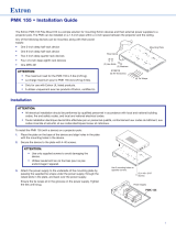
Figure 1. PoleVault IP System Installation and Wiring Overview
PoleVault IP Systems • Introduction
2

Before You Begin — Planning the Installation
Before installation is started, you must be consider several major factors to ensure that the
installation process is as smooth and trouble free as possible, and so that the final finished
project meets the needs of the customers, users, audiences, and installer.
The installation considerations on the following pages, though not comprehensive, should
be consulted to help ensure that key installation aspects have been considered.
Americans with Disabilities Act (ADA) Compliance
When planning where to install the Polevault System, you may need to consider factors
affecting accessibility of the system such as the height of devices from the floor (for example
the MLC controller), distance from obstructions, and how far a user must reach to press any
device buttons.
For guidelines, see sections 307 (“Protruding Objects”) and 308 (“Reach Ranges”) of the
2010 ADA Standards for Accessible Design available at http://www.ada.gov/regs2010/2
010ADAStandards/2010ADAStandards.pdf
Room Layout
a. The Room
The application diagram below shows a typical classroom installation.
CONFIG
DISPLAY
VOLUME
1
2
3
4
ON
OFF VCR
DVD
PC
Extron
MLC 104 IP Plus
PoleVault System
CONFIG
DISPLAY
VOLUME
1
2
3
4
ON
OFF
VCR
DVD
PC
Extron
MLC 104 IP Plus
PoleVault Syste
Figure 2. Typical Classroom Installation
Room factors to be considered should include, but are not confined to:
• Room size, orientation, and layout:
• Audience factors (for example number, ADA requirements, seating arrangements)
• Existing installed furniture (bookcases, racks, cabinets, workbenches, sinks, and so
forth.)
• Windows, doors, and support pillar locations in relationship to the proposed screen
location
PoleVault IP Systems • Introduction 3

• Ceiling and wall type (important in assessing the hardware needed)
• Ceiling type: dropped, spline, hard lid and similar. Structural type (wood, concrete,
trusses), plenum or non-plenum
• Wall type: drywall, cement, brick.
WARNING: Structural ceiling failure could cause death serious injury or
death. Check the structural ceiling to ensure that it can handle a load four
times the weight of the final setup.
• Lighting
• Type and control (important for projector image viewing)
• Ambient light from windows
Student Desks
Teacher’s Desk
TV / VCR / DVD
Inputs
Screen/White Board
Location
Windows
MLC controller
Location
PVT A/V Wallplate Location
Projector/Switcher
Location
Speaker
Location
Figure 3. Example Classroom Installation
b. Location of the Screen and Projector
• Proposed screen location (normally located at the front center of the room)
• The lowered screen does not cover safety devices, such as fire alarm strobes.
• Dimensions and type of screen (maximum image size, motorized or hanging screen)
• Proposed projector location
• Projector aligned with center of the screen and not an obstruction to viewing
• Projector throw distance (maximum and minimum limits to the screen) of the image
• Horizontal offset (horizontal distance from the center of the lens to the center of the
projector)
• Vertical offset of the projected image (height relationship between the projector and
the screen)
• Projector angle (image projected up, down, or horizontal to screen)
• Power source for the projector: existing and accessible or needing installation
• Projector weight: the Universal Projector Bracket (UPB 25) supports a maximum
weight of 25 lbs.
• Viewing obstructions: Pillars, furniture and so forth, window locations for glare
reduction, obstructions between projector and screen.
• Overhead clearances (refer to a copy of ADA Standards for Accessible Design,
Sections 307 and 308, for ADA requirements)
PoleVault IP Systems • Introduction
4

c. Location of MediaLink® Controller and Wall Plates
• Forward and side reach (for full details refer to a copy of ADA Standards for Accessible
Design, Sections 307 and 308, for ADA requirements).
• Location of source devices
Desk, table, or rack mounted, and proximity to proposed transmitter location (wall,
podium, or furniture)
• Cabling obstacles
Studs, utility pipes, power supply location (raceway installation needed?)
• Network drop for MediaLink Controller
Wall or floor cabled
d. Type and Location of the Speakers
• Speaker type based on room ceiling and wall type
• Total number and spacing of speakers
Based on ceiling height and room size
• Audience seating and room acoustics
Desired spread and evenness of sound coverage and ambient noise level compensation
Student Desks
Teacher’s
Desk
TV / VCR / DVD
Inputs
Screen/White board
Location
Windows
MLC controller
Location
PVT A/V Wallplate Location
Projector/Switcher
Location
Speaker
Location
Each speaker covers
one-fourth of
listening area.
Figure 4. Example Classroom with Four Speaker Installation
PoleVault IP Systems • Introduction 5

Inventory
Included Items
The PoleVault IP System (featuring the PVS 305SA IP switcher) ships in one box.
The box (80-xxx-13) contains the devices, hardware, and FF 120 speakers.
Carefully check all the received items against the lists on this and the next page.
PoleVault IP System
80-200-13 (or 80-300-13, or 80-400-13)
PMK 550
Pole Mount Kit
PMK 550 White
70-655-13
(4) 10-32 Cover screws
(3) 4-40 screws
(2) Velcro
™
pads
(1) Tie wrap
PoleVault
®
IP System Devices
and Hardware
PCM 340
UPB 25
PMK 550
CABLES
(1) SPK 18, 35 ft
(1) MLC, PW/RS232/VC, 50 ft
(1) IR SERIAL COMM, 50 ft
(1) MVGA M-M, 3 ft
(1) V RCA, 3 ft
CAT5 T568A Patch, 50 ft
Quantity varies depending
on PVS system ordered.
These may be boxed separately
or loose inside larger box.
The PVS 305SA IP may come
pre-installed on the PMK 550
(1) Snap-in trim piece
(4)Turnbuckles
(5) Lag eye bolts
(5) Concrete anchors
(2) Cable clamps, Gal Steel
(1) Safety wire (15 ft. 1/8 in. dia)
(2) Tie wire (30 ft., 14 AWG)
(4) T-frame screws
(2) Set screws
(1) Location screw
(11) Hole plugs
(4) Adhesive pads
(1) 25 in. Slotted pipe
(1) Escutcheon ring
PCM 340
Projector Drop Ceiling Mount
PCM 340 White
70-656-23
Accesories
UPB 25 White
60-773-03
UPB 25
Universal Projector Bracket
(4) M6 x 40 mm screws
(4) M5 x 40 mm screws
(4) M4 x 40 mm screws
(4) M3 x 40 mm screws
(4) 0.328 ID washers
(4) #10 washers
(4) #6 washers
(4) Adhesive pads
(1) Hex key
Accesories
Accesories
NOTE�Items not drawn to scale
• PVS 200IP (part number 80-200-13) includes one PVT RGB D IP Plus and one PVT CV D
• PVS 300IP (part number 80-300-13) includes one PVT RGB D IP Plus, one PVT RGB D, and one PVT CV D
• PVS 400IP (part number 80-400-13) includes one PVT RGB D IP Plus, one PVT RGB D, and two PVT CV D
PoleVault IP Systems • Introduction
6

PoleVault IP System
80-200-13 (or 80-300-13*, 80-400-13*)
MLC 104 IP Plus White
60-818-03
MLC 104 IP Plus
PVS 305SA IP
60-986-01N
PVS 305SA IP
PoleVault IP Switcher
(1) 2-pole connector
(1) 3-pole connector
(3) 5-pole connector
(1) Audio connector, 4-pole
(2) Securing screws
(5) Tie wraps
PVS 305SA IP
(1) Power supply
(1) Power cord
PoleVault IP System Devices
and Hardware, cont’d
PVT CV D
Wallplate
PVT CV D White
60-819-33
(1) Mud ring
(2) PVT mounting screws
(1) Decora
®
Faceplate
(2) Faceplate screws
(1) 2-pole connector
(1) Tie wrap
*Systems 80-300-13 and 80-400-13 contain
3 or 4 PoleVault Wallplates, according to the type ordered.
PVT CV D
PVT RGB D
Wallplate
PVT RGB D IP Plus White
60-1146-03
(1) Mud ring
(4) PVT mounting screws
(1) Decora
®
Faceplate
(4) Faceplate screws
(1) 2-pole connector
(1) Tie wrap
PVT RGB D IP Plus
or optional
PVT RGB D White
60-1066-03
PVT RGB D IP Plus
Wallplate
FF 120
Speakers
FF 120
42-120-03
(2) Cable clamps - Anchor ring
(2) T-rails
FF 120
AUDIO IN
L
R
VIDEO IN
IR OUT
S G
MLC 104 IP Plus
MediaLink Controller
(1) Mud ring
(2) Mounting screws
(4) Faceplate screws
(2) Faceplates -
(1) White (on unit)
(1) Black
CONFIG
DISPLAY
VOLUME
MLC 104 IP Plus
ON
VCR
DVD
PC
OFF
1
2
3
4
COMPUTER IN
AUDIO
IN OUT
MONITOR OUT
IR OUT
S G
CAT5e
CAT5e
This item may come pre-installed
on the PMK 550
PVS 305SA IP
POLEVAULT SWITCHER
INPUT SELECTION
1
2
PEAK
NORMAL
SIGNAL
CONFIG
34
5
AUX AUDIO
AUDIO LEVEL ADJUST
PAGING
SENSOR
SENSITIVITY
VOICELIFT
MIC
PEAK
NORMAL
SIGNAL
INPUT
COMPUTER IN
AUDIO IN
IR OUT
S G
Kits
• PVS 200IP (part number 80-200-13) includes one PVT RGB D IP Plus and one PVT CV D
• PVS 300IP (part number 80-300-13) includes one PVT RGB D IP Plus, one PVT RGB D, and one PVT CV D
• PVS 400IP (part number 80-400-13) includes one PVT RGB D IP Plus, one PVT RGB D, and two PVT CV D
NOTE: If any items in the PoleVault System boxes are damaged or missing, contact the Extron Technical Hotline
(see rear cover for contact numbers).
PoleVault IP Systems • Introduction 7

• Dry wall saw and hacksaw blade mounted
on handle (for cutting ceiling tiles)
• Flashlight and safety goggles
• Razor knife
• 2 inch hole saw
• Painter’s tape (to mark up walls), pencil, and
marker pen
• RJ-45 crimpers and RJ-45 connectors
• Voltage tester
• Fish tape, pull string, and electrical tape (for
taping fish tape to pull string)
• Zip ties
• Vacuum cleaner
• Heat gun
Items Not Included
The following items are not included. However, input and display devices are essential
parts of the system, and at any installation they may vary depending on their use. This list
suggests various devices that may be used.
• Projector (or display device)
• Screen (and mounting hardware)
• Input devices, such as:
• BluRay, DVD/CD/VCR combo player (and cables)
• Document camera (and cables)
• PC or Mac computer (with keyboard, mouse, local monitor, VGA cables, RJ-
45 network cables, power cords, and, where desired, a P/2 DA2 or Distribution
Amplifier (DA) for PC signal to local monitor)
• Installation hardware needed (may vary per installation):
• Bolts for concrete structural ceilings where needed
• Toggles (used for screen mounting on dry wall)
• S-hooks for hanging the screen
• Spare ceiling tiles in case of accidental damage during installation
• Electrical box, where installation of a box on the PCM 340 is desired
• Safety wire, lag eye bolts, and strain reliefs for installation and securing ceiling
speakers
• Heat shrink, extension cord
Installation Tools
To aid the professional installer, this checklist gives the tools recommended to complete
the installation. Tools should include, but are not confined to:
• Laser level, or two levels (large for
screen installation, small for wall plates
and projector mounts)
• Tape measure
• Stud finder
• Drill and drill bit set including a Unibit to
cut through metal studs
• Extension drill bit (3/4 inch min., 4 to 8
foot length, to drill through fire-breaks)
• Socket set
• Pipe strap or wrapped pipe wrench
• Pliers and wire strippers
• Standard screwdriver set and Extron
Tweeker
• Cable cutters (to cut safety wire)
PoleVault IP Systems • Introduction
8

Installation
Overview
This overview outlines the basic steps for installing the PoleVault IP System. An outline and
checklist of the stages (Stages One through Five), listing the relevant steps within each
stage, is given on page 10 and rear cover.
A fully detailed description of these steps is given in the five corresponding sections.
Carefully check inventory of PoleVault IP System packages, input and output devices, any
optional accessories, and installation hardware before commencing.
NOTES:
• Additional installation hardware is needed for this installation, and should be
supplied by the installer. See Items Not Included on page 8 for a list of items that
you may need.
• Refer to local building standards and codes to verify that the installation will meet all
the regulatory requirements.
• Observe all local and national building and safety codes, UL requirements, and
ADA Accessibility Guidelines.
PoleVault IP Systems • Installation Overview 9

Outline of Installation Steps
Stage 1 — Install the Screen and Projector
c Mark the screen location (page 12).
c Install projector to verify location (page 12).
c Verify the image location (page 15).
c Cut the ceiling tile (page 16).
c Preliminary safety hardware installation (page 16).
c Finish projector drop ceiling mount installation (page 17).
c Secure the projector drop ceiling mount to the ceiling (page 18).
c Install the electrical box (if required) (page 19).
c Install the screen (page 19).
Stage 2 — Mount the PVT Wall Plates and the MLC 104 IP Plus.
c
Install the mud rings (page 23).
c Pull cables (at the input locations) (page 24).
c Install the wall plates (page 25).
c Install the MediaLink Controller (page 26).
Stage 3 — Install the FF 120 Speakers.
c Cut the ceiling tile (page 30).
c Install the speaker on the drop ceiling (page 30).
c Terminate the speaker cable for the PVS switcher (page 32).
Stage 4 — Install the PMK 550 and the PVS 305SA IP.
c Install the PMK 550 base plate (page 34).
c Pull the cables (at the switcher location) (page 35).
c Finish installing the pole mount kit (page 36).
Stage 5 — Configure the PoleVault Switcher and the System.
c Configure the switcher — MLS Switcher Configuration program (page 37).
c Configure the system — Global Configurator (page 38).
c Test the system (page 39).
c Final installation (page 41).
The following pages contain instructions for installing the PoleVault IP System. Where possible, line drawings and
photos from an actual installation are used to clarify some of the steps discussed in the text. Most images have a
number corresponding to the step that is being described (for example,
Ñ
).
PoleVault IP Systems • Installation Overview10

PCM 340 Projector Drop Ceiling Mount
a
• Where it goes: Attaches to a structural ceiling,
rests on the suspended ceiling.
• What it does: Holds the slotted pipe, PoleVault pole
mount kit (PMK 550), and projector.
Slotted Pipe
b
• Where it goes: Locks into place in the PCM 340 pipe
adapter.
• What it does: Holds the PMK 550 pole mount kit,
UPB 25 Projector Bracket and projector.
UPB 25 Universal Projector Bracket
(separated into two sections)
c
• Where it goes: Adjuster Plate screws onto the base of
the slotted pipe, and the Projector Bracket attaches to
the projector.
• What it does: Attaches the projector to the PCM 340.
Allows proper projector positioning and orientation.
T-bar
Securing
Screws (4)
Slotted
Pipe
Adjuster Plate
(Top Section)
Pipe Adapter Plate
Wing Nuts (4)
3
2
1
1-gang and 2-gang Accessory Mounting
Points (e.g., Power Sockets)
Pipe
Adapter
Base
Plate
Pipe Adapter
Set Screws (2)
Stage 1:
Installing the Screen
and Projector
Stage 1 Involves Installing Three Pieces of Hardware Shown Below.
PoleVault IP Systems • Installation — Stage 1 (Screen and Projector)
11

1. — Mark Screen Location
TIPS:
• When marking the location of screens,
devices, or the site for installing
transmitters and MediaLink control
devices, use painters tape to avoid wall
surface damage.
• When marking the center line of the
screen, where possible, keep it aligned
with the center of the ceiling tile. This
makes the projector installation and
alignment easier.
a. Mark the center line and the outer edges of the
screen.
b. Mark any structural studs, utility pipes, conduits,
or fire breaks before drilling the hardware holes.
Do not drill the holes yet.
2. — Install Projector to Verify Location
a. Remove the ceiling tiles at the location, and
mark the maximum and minimum throw
distances on the T-frame.See the projector
installation manual for more information.
TIP: For ease of working on the T-frame
remove the adjacent tiles.
b. Place the PCM 340 over the T-frame, between
the two marks. Lightly tighten the T-frame
securing screws. The T-frame screws can be
used on the outside or the inside to secure the
PCM to the T-frame.
NOTE: Place the PCM 340 on the T-frame
so that the pipe adapter slides left to right
in relation to the proposed screen location,
rather than towards and away from it. This
makes it easier to align and center the
image.
c. Slide the slotted pipe up into the pipe adapter.
Adjust to the desired height and align the
location holes and pipe holes. Insert the location
screw, lightly tightening it down using a
5/32 inch hex wrench. Insert and lightly tighten
down the set screws onto the pipe. Do not
overtighten. The pipe is removed and replaced
later during installation.
PCM 340
Minimum/Maximum
Throw Distance Marks
É
Place the PCM 340 on the T-bar
Ä
Mark the screen location.
î
Insert and secure the slotted pipe.
Align Pipe holes with
location screw holes.
Insert location screw
and secure.
Pipe
Adapter
Slotted
Pipe
PoleVault IP Systems • Installation — Stage 1 (Screen and Projector)12

ï
Screw the adjuster plate onto the base of
the pipe.
d. Using a 3/32 inch hex wrench, back out the
set screws on the top portion of the adjuster
plate (see a in the image below) of the UPB 25.
Screw the plate onto the base of the pipe. Align
it so the security flange is at the rear
Adjuster Plate
Locking Screws (4)
Projector
Bracket
Adjuster
Plate
Loosen the four Adjuster Plate
Locking Screws and slide the
Adjuster Plate away from the
Projector Bracket
a
b
Set Screws (2)
Security flange
e. Carefully follow the steps below to install the
projector bracket on the projector.
i. Invert the projector on a flat surface to access
the mounting points. Use a blanket or a
similar item under the projector to protect the
projector and the surface.
ii. On each arm, rotate the barrel (on the end
of the arm) so that it only just protrudes from
the base of the arm (see the figure at right).
iii. Select the correct sized mounting screws and
the appropriately sized washers that fit the
projector mounting point inserts.
iv. To attach the arms to the projector:
The next step is critical as it provides a
flat surface for the bracket to sit on, and
must be done for each mounting point.
• Place a washer on a mounting point (see
the figure at right).
• Position the arm so the barrel is over the
washer.
• Insert the mounting screw down through the
barrel and washer, and into the threaded insert
(mounting point). Lightly tighten the screw by
hand.
NOTE: If using the 3- or 4-millimeter
screws, place an additional small washer
under each screw head, on top of the
barrel, as well as one on the top of the
mounting point.
v. Repeat step iv for all projector mounting
points.
Rotate the barrel
until it just protrudes
below the arm.
ii
Mounting Point
on Projector Base
Place washer on
mounting point.
ATTENTION:
Ü
iv
This is critical as it provides a flat surface
for the bracket to sit on.
Place the washer Align the barrel Insert the screw
PoleVault IP Systems • Installation — Stage 1 (Screen and Projector) 13

Using the slot closest
to the barrel, secure the
arms to the bracket with
the clamp and screw.
vi. Pivot the arms so that they extend towards
the center of the projector (see the figure at
right). Adjust the arms as needed for your
projector model.
NOTE: Avoid overlapping the arms where
possible.
vii. With the security flange towards the rear of
the projector, place the projector bracket on
top of the arms and adjust for slot alignment.
• Using the slots on the bracket that are
closest to the barrel on each arm, place the
clamp under the arm and lightly secure it to the
bracket with the adjustment screws (see the
figure at right). Loosely secure all the mounted
arms.
NOTE: Where arms are unavoidably
crossed, replace the original adjustment
screw with a supplied 10-32 ¾ inch
adjustment screw and secure both
arms to the bracket using one clamp. In
addition, the barrels on the arms must be
raised to compensate, keeping the arms
level and reducing stress.
viii. As close as possible, balance the weight
of the projector evenly across the projector
bracket. Lift the bracket at opposite corners
to assess if the configuration is approximately
balanced.
ATTENTION: Take into consideration the
uneven weight distribution of the projector
when lengthening or shortening the arms.
Distribute the projector weight evenly on
the arms.
Adjust the bracket on the arms as needed.
The projector shown at right is as close as
possible to being evenly balanced.
Washer
Arms
Clamp
Bracket
Where arms cross, use the
supplied screw to secure
both arms to the bracket.
See note at left.
vi. Pivot arms towards center of projector.
vii. Secure arms with clamp
Note: If arms cross, secure both with clamp
viii. Evenly balanced conguration
PoleVault IP Systems • Installation — Stage 1 (Screen and Projector)14

ix. Check for stress on the arms. To do this
loosen the mounting screws (do not remove).
If the arm or the barrel lifts, this indicates
stress on the arm. Adjust the height of the
threaded barrels to reduce or eliminate
any torque or stress that might be caused
by crossed arms or by projector mounting
points with differing heights. It is important to
keep the arms level and as close (low) to the
projector base as possible.
x. Check that the projector weight is still as
evenly distributed as possible.
Hand tighten the screws until snug.
ATTENTION: Do not overtighten the
mounting screws as this may damage the
projector. See the projector manual for the
threaded insert torque setting.
f. Lift the projector up to the adjuster plate and
slide it into place. Tighten down the locking and
pivot screws.
3. — Verify the Image Location
a. Connect a power cable to the projector and
turn it on.
b. Verify image size and location by loosening the
PCM 340 pipe adapter plate wing nuts, and
adjust the plate (left-right) to center the image.
TIP: Remember to include the vertical and
horizontal offsets when aligning the projector.
See the projector manual for information
c. When satisfied, tighten down the plate wing
nuts.
ß
Slide and lock the projector onto the
adjuster plate.
Projector
Center Line
Lens
Center Line
Measure the
horizontal offset
⊗
INCORRECT CORRECT
Arm not level, causing stress Arm level, no stress
on mounting point on mounting point
Loosen the screw and adjust
the barrel height to reduce torque
on the arms and bracket.
Tighten down all the
mounting screws.
Washer
TIP: Horizontal offset
PoleVault IP Systems • Installation — Stage 1 (Screen and Projector) 15

à
Mark the structural ceiling for lag eye
bolt installation.
4.— Cut the Ceiling Tile
a. Mark the location of the PCM 340 on the
T-frame. This aids putting it back in the correct
location when the tile is replaced.
TIP: Mark the screen direction on back
of the tile (for example with an arrow or
“to front”) to help orientation of tile when
replacing it after cutting
b. Measure the distances X and Y (see the figure
at right) from the inner vertical section of the
front and left T-frame runners to the center of
the Pipe Adapter Plate.
Using the X and Y dimensions, mark and cut a
hole for the slotted pipe in the ceiling tile.
TIP: Place the tile on a box and mark the
center of the hole on the underside of the
tile. Use a hole saw bit to start to cut the
hole by hand (turning bit counter clock-
wise) to avoid damaging the tile. When the
drill bit is through the tile, turn the tile over
and finish cutting from the top side
5. — Preliminary Safety Hardware Installation
a. Mark and drill holes at 10 degrees out from
vertical for each turnbuckle. Drill a fifth hole
directly centered above the PCM 340 for the
safety cable.
b. Install an appropriate anchors or lag eye bolt for
the structural ceiling into each drilled hole.
Underside of Tile
Top Side of Tile
T-bar
X"
Y"
Minimum and
Maximum
Throw Distance Marks
á
Take the measurements with the PCM 340
on the T-frame.
TIP: Mark and start cutting the hole on the
underside. Finish on the top side.
PoleVault IP Systems • Installation — Stage 1 (Screen and Projector)16
/