Y,
Y,
--)
READAND UNDERSTANDTHESEINSTRUCTIONSBEFOREINSTALLINGFIXTURE
INSTRUCTION SHEET NO.
jis fixture is intendedfor installationin accordancewith the National ElectricalCode and local
gulafions.
To sssurefullcompliancewithIota walesandregulations,checkwithyourlocalelectrid
specterbeforeInstallation.Topreventelectricalshock,turnoftelecfncifyatfuaeboxbeforeproceeding.
IS:1000P1
Retain these instructions for maintenance reference.
0792
INSTALLATION PROCEDURE FOR FRAME-IN KIT 1000P1
WARNING-(RISKOFFIRE)
DONOTINSTALL
INSULATIONWITHINTHREEINCHESOFFIXTURESIDESOR
WIRINGCOMPARTMENT,NORABOVEFIXTUREINSUCHA
MANNERTO ENTRAPHEAT.
L FRAME-IN AND WIRE-IN
Line
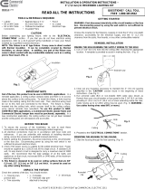
up bOftOMadoa OrADJUSTABLEMOUNTINGBARwithbottom
ofwoodjoist(Fig.A), Fasten MOUNTINGFRAMEtowoodjoistby
naifingMOUNTINGBARTABor
nail into joist, Wire to supply leads,
White fixture lead to neutral supply lead, Black fixture lead to hot
(120V.) supply lead. Bare tixtura wirs to supply ground, Uss wirenuts
(local hardware items). Place all electrical connections in the J-BOX.
Attach J. BOX COVER onto J.BOX. (Use built+ CABLE CLAMP in J-
BOX for non.metalfic sheathed cable (Romax), or ARMORED CABLE
(BX).)
%
TAB
~OTES
1. ADJUSTABLE MOUNTING BARS can bs installed aither on long
or shori sida of MOUNTING FRAME. Locking screws are provided
to lock frame in a desired position.
0
OCCQ )r
2. MOUNTING BARS can be extended to 24”. The MOUNTING
FRAME can ba mounted oti-center. Atign SLOT of one
SCREW
MOUNTING BAR with hola of the other MOUNTING BAR and
MOUNTING FRAME
drive scrsw into hole. Take ptiers and bend tab on MOUNTING
FRAME over towards extended MOUNTING BAR until
\
MOUNTING FRAME no longer slides along MOUNTING BARS.
(fig, B) CENTERING SLOTS are provided as guides to afign
MOUNTING BAR
adjacent frames.
3. For suspended ceihngs, make cetiain that bonom of MOUNTING
FRAME is no higher than 1” above ceiling tine, and notched area
of ADJUSTABLE MOUNTING BARS ara posifionsd on top of T
BAR. (Fig. C)
F,GB’4
. . . .
C.
CLOSE-IN
Install in plasterboard or other dry type ctiling, Hole in board can be
241$
cut either on floor or after the board is nailsd to the ceikng, using
MOUNTING FRAME opening as cutting guide (make sure ROTO
CLIPS me rotated out of hole area). ROTO CLIPS cm only be rotated
counterclockwise. This detail allows easy removal of REFLECTOR
TRIM by rotating TRIM counterclockwise and permits installing
REFLEcTOR TRIM tightly against the ceifing surface by rofating TRIM
clockwise after pushing TRIM into ceiting.
NOTE:
For wst plaster ceifing, use Plaster Ring Accessory No. 19B0 (order
separately),
1
SEE SEPARATE
D. ATTACH SOCKET TO TRIM REFLEcToRTR]M
INSTRUCTION SHEETS.
F. PUSH-UP
WARNING: USEONLYWITHTRIMSDESIGNATEDBY
LIGHTOLIERINC.USEOFOTHERMANUFACTURERS’TRIMS
VOIOSTHEUNDERWRITERSLABORATORIESLISTINGAND
COULDCONSTITUTEA FIREHAZARD.
9-B <51“17-<> 1-9 1= la i%%%’,%%waa’::

