Page is loading ...

Not for
Reproduction

Not for
Reproduction
2 ferrismowers.com | snapperpro.com
Table of Contents:
General Information..............................................................3
Products Covered by this Manual.......................................3
Operator Safety..................................................................... 3
Safety Rules and Information...........................................3
Safety Decals................................................................... 4
Safety Icons......................................................................4
Installation............................................................................. 4
Rear Suspension Adjustment (Models Equipped with
Rear Suspension).............................................................5
Remove the Carburetor Shield.........................................6
Install the Hopper Mounting Plate....................................6
Install the Stabilizer Straps (Models with Flat Plate
Bumpers)........................................................................ 10
Install the Support Plate and Latch Bar Assembly......... 12
Install the Torsion Tube................................................. 12
Install the Mount Tube and Latch Bar Assemblies to the
Support Plates................................................................ 12
Install the Latch Bar Assembly Tensioning Spring......... 13
Install the Dump Handle Assembly................................ 13
Install the Rod Pivot Mount............................................ 14
Install the Dump Handle Linkage Rods..........................14
Connect the Latch Bar Assemblies to the Latch Bar...... 15
Install the Door Latch Rod............................................. 15
Install the Winch Anchor Bracket................................... 15
Install the Winch Quick Mount....................................... 16
Install the Weights and Weight Mounts..........................16
Install the Handle on the Winch..................................... 17
Install the Hopper to the Hopper Mount......................... 17
Adjust the Dump Handle Position.................................. 18
Adjust the Latch Bar Assemblies................................... 18
Adjust the Dump Handle Linkage Rods......................... 18
Install Tube Extension to Hopper................................... 19
Install Hose to Hopper Assembly................................... 19
Install Hose to Blower Assembly....................................19
Operation............................................................................. 20
General Operating Instructions...................................... 20
Opening and Closing the Hopper...................................21
Lubrication...................................................................... 21
Troubleshooting.................................................................. 22
Troubleshooting Charts.................................................. 22
Unplugging a Clogged Unit............................................ 22
Collector System Removal................................................ 23

Not for
Reproduction
3
General Information
Thank you for purchasing this quality-built grass collection
system. When operated and maintained according to the
instructions in this manual, your grass collection system will
provide you many years of dependable service.
This manual contains safety information to make you aware
of the hazards and risks associated with this product and
how to avoid them. This product is designed and intended to
be used and maintained according to the manual for grass
collection from established lawns and is not intended for any
other purpose. It is important that you read and understand
these instructions thoroughly before attempting to operate
this equipment. Save these original instructions for future
reference.
These setup instructions are to be done in addition to the
Blower and Blower Mount installation instructions detailed
in the blower's operators manual included with the blower
mount.
You must observe and obey all safety instructions in the
blower's operator's manual along with all instructions detailed
in this manual.
The images in this document are representative, and
are meant to complement the instructional copy they
accompany. Your unit may vary from the images
displayed.LEFTandRIGHTare as seen from the operator's
position.
Date of
Purchase:
Copyright © Briggs & Stratton Corporation, Milwaukee, WI,
USA. All rights reserved.
FERRIS is a trademark of Briggs & Stratton Corporation,
Milwaukee, WI, USA.
SNAPPER PRO is a trademark of Briggs & Stratton
Corporation, Milwaukee, WI, USA.
Products Covered by this
Manual
TURBO-Pro Blower w/ 12 cu. ft. EZ Dump Hopper
System
Number
Description
5600901 Kit, 12 cu. ft. EZ Dump Hopper w/ TURBO-Pro MAX
Blower, 61", 200XT, IS2100Z, F210Z
5600902 Kit, 12 cu. ft. EZ Dump Hopper w/ TURBO-Pro MAX
Blower, 52", IS2100Z
5600904 Kit, 12 cu. ft. EZ Dump Hopper w/ TURBO-Pro MAX
Blower, 52", 150XT, F160Z
5601243 Kit, 12 cu. ft. EZ Dump Hopper w/ TURBO-Pro MAX
Blower, 52", ISX2200
5601245 Kit, 12 cu. ft. EZ Dump Hopper w/ TURBO-Pro MAX
Blower, 61", ISX2200
FAST-Vac® Blower w/ 12 cu. ft. EZ Dump Hopper
System
Number
Description
5600903 Kit, 12 cu. ft. EZ Dump Hopper w/ FAST-Vac® Blower,
61", 200XT, IS2100Z, F210Z
5600905 Kit, 12 cu. ft. EZ Dump Hopper w/ FAST-Vac® Blower,
52", 150XT, F160Z
5600906 Kit, 12 cu. ft. EZ Dump Hopper w/ FAST-Vac® Blower,
52", IS2100Z
5601242 Kit, 12 cu. ft. EZ Dump Hopper w/ FAST-Vac® Blower,
52" ISX2200
5601244 Kit, 12 cu. ft. EZ Dump Hopper w/ FAST-Vac® Blower,
61" ISX3300
TURBO-Pro Blower w/ 14 cu. ft. EZ Dump XL Hopper
System
Number
Description
5600910 Kit, 14 cu. ft. EZ Dump XL Hopper w/ TURBO-Pro MAX
Blower, 61", IS3200Z, F320Z
5600900 Kit, 14 cu. ft. EZ Dump XL Hopper w/ TURBO-Pro MAX
Blower, 61", S200XT
5900940 Kit, 14 cu. ft. EZ Dump XL Hopper w/ TURBO-Pro MAX
Blower, 61", F210Z
5601241 Kit, 14 cu. ft. EZ Dump XL Hopper w/ TURBO-Pro MAX
Blower, 61" ISX3300
FAST-Vac® Blower w/ 14 cu. ft. EZ Dump XL Hopper
System
Number
Description
5600907 Kit, 14 cu. ft. EZ Dump XL Hopper w/ FAST-Vac®
Blower, 61", IS3200Z, F320Z
5600909 Kit, 14 cu. ft. EZ Dump XL Hopper w/ FAST-Vac®
Blower, 61", S200XT
5600941 Kit, 14 cu. ft. EZ Dump XL Hopper w/ FAST-Vac®
Blower, 61", F210Z
5601240 Kit, 14 cu. ft. EZ Dump XL Hopper w FAST-Vac® Blower,
61" ISX3300
Operator Safety
In addition to all of the safety instructions described in this
manual, you must obey all the safety instructions in the
blower's operators manual included with the blower mount.
Safety Rules and Information
Read these safety instructions and follow them closely.
Failure to obey these rules could result in loss of control of
unit, severe personal injury or death to you, or bystanders, or
damage to property or equipment.
This mowing deck is capable of amputating hands and
feet and throwing objects.
The triangle ( ) in text signifies important cautions or
warning which must be followed.

Not for
Reproduction
4 ferrismowers.com | snapperpro.com
WARNING
• Check the collection system to make sure it is bolted
tightly to the rider.
WARNING
• When blower assembly is removed from the mower
deck, the deflector must be properly installed.
WARNING
Amputation and thrown objects hazard
If the mower stalls or the turbo blower chute plugs:
1. Disengage the blower (blades) and remove the ignition
key and wait for all parts to stop before disconnecting
or unlatching any parts attached to the blower or the
collection system.
2. Remove the foreign object or clear the chute with a
suitable tool, such as a broom handle, before restarting
the engine. NEVER place hands into the blower
housing to clear jammed objects. Blower may rotate
when object is removed.
WARNING
For added rider stability and to prevent tipping or loss of
control:
• Use reduced speed on uneven ground and when
turning corners.
• Reduce loads on hillsides. It is recommended that the
collection system be kept no more than half full when
negotiating any slopes. Start mowing on slopes when
the collection system is empty.
Safety Decals
Before operating your unit, read the safety decals. The
cautions and warnings are for your safety. To avoid a
personal injury or damage to the unit, understand and follow
all the safety decals.
WARNING
If any safety decals become worn or damaged and cannot
be read, order replacement decals from your dealer.
A. Part Number: 5104315 - Decal, Container, Icons
Safety Icons
Warning - Thrown objects hazard:
• Do not open collection system container with engine
running.
• Do not operate with blower or collection system tube
unlatched or missing.
• Operate only with both the entire collection system and
front counterbalance weights installed and the collection
system closed and latched.
Warning - Loss of traction and control hazard:
• Do not operate with only the collection system installed.
• Do not operate with only the front counter balance
weights installed.
• Operate only with both the entire collection system and
front counter balance weights installed and the collection
system closed and latched.
Installation
In addition to these installation instructions, perform the
installation instructions for the blower and blower mount that
are detailed in the blower's operators manual included with
the blower mount.

Not for
Reproduction
5
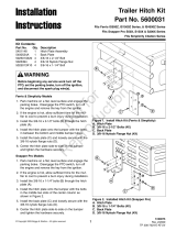
Rear Suspension Adjustment (Models
Equipped with Rear Suspension)
Many units equipped with rear suspension has multiple upper
mounting positions for the rear shock assembly (A, Figure
1). If the unit that you are installing the collection system
on is equipped with rear suspension, the upper mounting
position of the rear shock assembly must be re-positioned to
accommodate the additional weight of the collection system.
1
Some units are equipped with two (2) upper shock mounting
positions and some units are equipped with three (3) upper
shock mounting positions. To accommodate the additional
weight of the collection system the upper end of the shock
mount assembly must re-positioned so that the shock is in its
most vertical orientation.
If the unit that you are installing the collection system on does
not have additional upper mounting positions, the spring's
pre-load must be adjusted. For unit's with additional upper
mounting positions: if a stiffer ride is desired after the rear
shock is re-positioned to it's most vertical position, it can be
achieved by adjusting the spring's pre-load.
To adjust the upper shock mounting position:
1. Park the machine on a flat, level surface. Engage the
parking brake, disengage the PTO, turn the ignition
switch to OFF, and remove the key from the ignition.
2. Chock the front wheels of the unit to prevent the machine
from rolling.
3. Raise the rear of the machine and secure with jack
stands. The jack stands must be positioned under the
bumper of the unit.
4. Position the jack under the suspension cradle (or the
cross member that ties the suspension arms together,
depending on your unit) and slowly raise the rear
suspension to relieve the pressure on the upper shock
mounting bolts.
Note:This will require small adjustments to the jacks position.
The shock should move freely on the mounting bolt when the
pressure is relieved.
5. Remove the upper shock mounting hardware and
pivot the shock to the position that orients the shock
most vertically (position #2 for units with two (2) upper
mounting positions; position #3 for units with three (3)
upper mounting positions). Adjust the jack to align the
shock assembly to the shock mounting hole.
6. Re-install the upper shock mounting hardware and
tighten securely.
7. Remove the jack from underneath the suspension cradle
(or suspension cross member, depending on your unit).
8. Remove the jack stands from underneath the machine.
To adjust the spring pre-load:
1. Park the machine on a flat, level surface. Engage the
parking brake, disengage the PTO, turn the ignition
switch to OFF, and remove the ignition key.
2. Chock the front wheels of the machine to prevent the
machine from rolling.
3. Raise the rear of the machine and secure with jack
stands.
4. Remove the rear drive tires.
WARNING
Use two hands when adjusting the shock assembly springs.
The will prevent the wrench from slipping while pressure is
being applied.
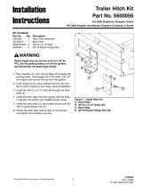
5. To adjust the spring pre-load of the shock assembly
(A, Figure 2) insert the tip of the spanner wrench (p/n
5022853) (B), that came with the zero-turn riding mower,
into the notch of the pre-load adjuster (C). While holding
the spanner wrench in place with one hand, turn counter-
clockwise to increase the amount of pre-load. (Turning
clockwise will decrease the amount of pre-load.) Make
sure that both rear shock assemblies are adjusted to the
same pre-load position.

Not for
Reproduction
6 ferrismowers.com | snapperpro.com
2
6. Re-install the rear drive tires. Torque the lug bolts to
85-91 ft. lbs. (115-129 Nm). Remove the jack stands from
under the machine.
Note:If the spanner wrench is not located in a clamp under
the seat plate of your unit, it was included with the publication
packet for the zero-turn riding mower.
Remove the Carburetor Shield
If a unit has a carburetor shield it must be removed prior to
installing the collection system.
Note:ISX2200 and ISX3300 series models DO NOT need
the carburetor shield removed.
1. If the engine is hot, allow sufficient time for the muffler to
cool to prevent a burn injury during installation process.
2. Remove the carburetor shield (A, Figure 3) from the top
of the rear bumper (B) by removing the hardware (C, D &
E) securing the shield to the bumper.
3
Install the Hopper Mounting Plate
All zero-turn riding mowers with mid-mounted mower decks
that this hopper collection system fits use the same hopper
mount plate but use different hardware and mounting holes to
mount it. Please refer to the following instructions and figures
for the proper mounting holes and hardware for mounting the
hopper mount.
Zero-Turn Riding Mowers with Round Tube
Bumpers
Four (4) 3/8 U-bolts (A, Figure 4) and eight (8) 3/8-16 hex
nylock flange nuts (B) are used to mount the hopper mount
(C) to the round tube bumper (D).
4

Not for
Reproduction
7
F160Z with 52" Mower Deck (12 cu. ft. Hopper)
1. Position the hopper mount plate onto the bumper and
install two (2) U-bolts over the top bumper tube and
through the holes indicated as "A" in Figure 5 and secure
with four (4) 3/8-16 nylock flange nuts.
5
2. Install two (2) U-bolts over the middle bumper tube and
through the holes indicated as "B" in Figure 5 and secure
with four (4) 3/8-16 nylock flange nuts.
3. Center the hopper mount plate on the bumper and tighten
the hardware.
IS2100Z with 52" Mower Deck (12 cu. ft. Hopper)
1. Position the hopper mount plate onto the bumper and
install two (2) U-bolts over the top bumper tube and
through the holes indicated as "A" in Figure 6 and secure
with four (4) 3/8-16 nylock flange nuts.
6
2. Install two (2) U-bolts over the middle bumper tube and
through the holes indicated as "B" in Figure 6 and secure
with four (4) 3/8-16 nylock flange nuts.
3. Center the hopper mount plate on the bumper and tighten
the hardware.
IS2100Z with 61" Mower Deck (12 cu. ft. Hopper)
1. Position the hopper mount plate onto the bumper and
install two (2) U-bolts over the top bumper tube and
through the holes indicated as "A" in Figure 7 and secure
with four (4) 3/8-16 nylock flange nuts.
7
2. Install two (2) U-bolts over the middle bumper tube and
through the holes indicated as "B" in Figure 7 and secure
with four (4) 3/8-16 nylock flange nuts.
3. Slide the hopper mount plate as far as it will go towards
the discharge side of the mower deck and tighten the
hardware.
ISX2200 with 52" Mower Deck (12 cu. ft.
Hopper)
1. Position the hopper mount plate onto the bumper and
install two (2) U-bolts over the middle bumper tube and
through the holes indicated as "A" in Figure 8 and secure
with four (4) 3/8-16 nylock flange nuts.
8
2. Install two (2) U-bolts over the bottom bumper tube and
through the holes indicated as "B" in Figure 8 and secure
with four (4) 3/8-16 nylock flange nuts.
3. Center the hopper mount plate on the bumper and tighten
the hardware.
ISX2200 with 61" Mower Deck (12 cu. ft.
Hopper)
1. Position the hopper mount plate onto the bumper and
install two (2) U-bolts over the middle bumper tube and
through the holes indicated as "A" in Figure 9 and secure
with four (4) 3/8-16 nylock flange nuts.

Not for
Reproduction
8 ferrismowers.com | snapperpro.com
9
2. Install two (2) U-bolts over the bottom bumper tube and
through the holes indicated as "B" in Figure 9 and secure
with four (4) 3/8-16 nylock flange nuts.
3. Slide the hopper mount plate as far as it will go towards
the discharge side of the mower deck and tighten the
hardware.
F210Z with 61" Mower Deck (12 cu. ft. Hopper)
1. Position the hopper mount plate onto the bumper and
install two (2) U-bolts over the top bumper tube and
through the holes indicated as "A" in Figure 10 and
secure with four (4) 3/8-16 nylock flange nuts.
10
2. Install two (2) U-bolts over the middle bumper tube and
through the holes indicated as "B" in Figure 10 and
secure with four (4) 3/8-16 nylock flange nuts.
3. Slide the hopper mount plate as far as it will go towards
the discharge side of the mower deck and tighten the
hardware.
F210Z with 61" Mower Deck (14 cu. ft. Hopper)
1. Position the hopper mount plate onto the bumper and
install two (2) U-bolts over the top bumper tube and
through the holes indicated as "A" in Figure 11 and
secure with four (4) 3/8-16 nylock flange nuts.
11
2. Install two (2) U-bolts over the middle bumper tube and
through the holes indicated as "B" in Figure 11 and
secure with four (4) 3/8-16 nylock flange nuts.
3. Center the hopper mount plate on the bumper and tighten
the hardware.
IS3200Z with 61" Mower Deck (14 cu. ft. Hopper)
1. Position the hopper mount plate onto the bumper and
install two (2) U-bolts over the top bumper tube and
through the holes indicated as "A" in Figure 12 and
secure with four (4) 3/8-16 nylock flange nuts.
12
2. Install two (2) U-bolts over the second bumper tube (from
the top of the bumper counting down) and through the
holes indicated as "B" in Figure 12 and secure with four
(4) 3/8-16 nylock flange nuts.
3. Center the hopper mount plate on the bumper and tighten
the hardware.
ISX3300 with 61" Mower Deck (14 cu. ft.
Hopper)
1. Position the hopper mount plate onto the bumper and
install two (2) U-bolts over the second bumper tube (from
the top of the bumper counting down) and through the
holes indicated as "A" in Figure 13 and secure with four
(4) 3/8-16 nylock flange nuts.

Not for
Reproduction
9
13
2. Install two (2) U-bolts over the third bumper tube (from
the top of the bumper counting down) and through the
holes indicated as "B" in Figure 13 and secure with four
(4) 3/8-16 nylock flange nuts.
3. Center the hopper mount plate on the bumper and tighten
the hardware.
F320Z with 61" Mower Deck (14 cu. ft. Hopper)
1. Position the hopper mount plate onto the bumper and
install two (2) U-bolts over the top bumper tube and
through the holes indicated as "A" in Figure 14 and
secure with four (4) 3/8-16 nylock flange nuts.
14
2. Install two (2) U-bolts over the second bumper tube (from
the top of the bumper counting down) and through the
holes indicated as "B" in Figure 14 and secure with four
(4) 3/8-16 nylock flange nuts.
3. Center the hopper mount plate on the bumper and tighten
the hardware.
Zero-Turn Riding Mowers with Flat Plate
Bumpers
3/8-16 X 1" bolts, 3/8 SAE washers, and 3/8-16 nylock flange
nuts are used to mount the hopper mount plate to the flat tube
bumper.
Please see the instructions below for your specific model,
mower deck size, and collection system as each installation
process is slightly different for units with flat plate bumpers.
S150XT with 52" Mower Deck (12 cu. ft. Hopper)
15
1. Position the hopper mount plate (A, Figure 15) onto the
bumper (B) and route four (4) 3/8-16 X 1" bolts (C) and
3/8 flat washers (D) through the holes identified as "A" in
Figure 16 and then through the bumper and secure with
four (4) 3/8 hex nylock flange nuts (E).
16
2. Route two (2) 3/8-16 X 1" bolts and 3/8 flat washers
through the holes identified as "B" in Figure 16 and then
through the bumper and the hopper mount backing plate
(F) and secure with two (2) 3/8 hex nylock flange nuts.

Not for
Reproduction
10 ferrismowers.com | snapperpro.com
S200XT with 61" Mower Deck (12 cu. ft. Hopper)
17
1. Position the hopper mount plate (A, Figure 17) onto the
bumper (B) and route four (4) 3/8-16 X 1" bolts (C) and
3/8 flat washers (D) through the holes identified as "A" in
Figure 18 and then through the bumper and secure with
four (4) 3/8 hex nylock flange nuts (E).
18
2. Route two (2) 3/8-16 X 1" bolts and 3/8 flat washers
through the holes identified as "B" in Figure 18 and then
through the bumper and secure with two (2) 3/8 hex
nylock flange nuts.
3. Route one (1) 3/8-16 X 1" bolt and a 3/8 flat washer
through the hole identified as "C" in Figure 18 and then
through the bumper and secure with one (1) 3/8 hex
nylock flange nut.
S200XT with 61" Mower Deck (14 cu. ft. Hopper)
19
1. Position the hopper mount plate (A, Figure 19) onto the
bumper (B) and route four (4) 3/8-16 X 1" bolts (C) and
3/8 flat washers (D) through the holes identified as "A" in
Figure 20 and then through the bumper and secure with
four (4) 3/8 hex nylock flange nuts (E).
20
2. Route two (2) 3/8-16 X 1" bolts and 3/8 flat washers
through the holes identified as "B" in Figure 20 and then
through the bumper and secure with two (2) 3/8 hex
nylock flange nuts.
3. Route two (2) 3/8-16 X 1" bolts and 3/8 flat washers
through the holes identified as "C" in Figure 20 and then
through the bumper and secure with two (2) 3/8 hex
nylock flange nuts.
Install the Stabilizer Straps (Models with
Flat Plate Bumpers)
Models with flat plate bumpers utilize stabilizer straps to help
mount the hopper mount plate to the unit. Each series, deck
size, and hopper combination has it's own specific stabilizer
straps and unique orientation. Your kit only has the stabilizer
straps for the machine the hopper kit that was purchased was
intended to be installed on.

Not for
Reproduction
11
Install the Stabilizer Straps - S150XT with 52"
Mower Deck (12 cu. ft. Hopper)
1. Using a 3/8-16 X 1-1/4" bolt (A, Figure 21), 3/8 SAE
washer (B) and 3/8-16 hex nylock flange nut (C) mount
the stabilizer strap (D) to the right side of the hopper
mount (E).
21
2. Remove the upper 3/8 bolt, washer, and nut that secures
the right hand side rear fuel tank bracket (F) to the unit.
3. Install a new 3/8-16 X 1-1/2" bolt (G) with a 3/8 SAE
washer (H) through the right hand side rear fuel tank
bracket, the frame of the machine, the stabilizer strap,
and secure using a 3/8-16 hex nylock flange nut (I).
4. Repeat this process for the other side of the machine.
Install the Stabilizer Straps - S200XT with 61"
Mower Deck (12 cu. ft. Hopper)
When installing a 12 cu. ft. hopper on a S200XT series
mower with a 61" mower deck. There is a left stabilizer strap
(A, Figure 22) and a right stabilizer strap (B) that is used.
22
1. Using a 3/8-16 X 1-1/4" bolt (A, Figure 23), 3/8 SAE
washer (B) and 3/8-16 hex nylock flange nut (C) mount
the stabilizer strap (D) to the right side of the hopper
mount (E).
23
2. Remove the upper 3/8 bolt, washer, and nut that secures
the right hand side rear fuel tank bracket (F) to the unit.
3. Install a new 3/8-16 X 1-1/2" bolt (G) with a 3/8 SAE
washer (H) through the right hand side rear fuel tank
bracket, the frame of the machine, the stabilizer strap,
and secure using a 3/8-16 hex nylock flange nut (I).
4. Repeat this process to install the left hand stabilizer strap
(J) onto the left hand side of the machine.
Install the Stabilizer Straps - S200XT with 61"
Mower Deck (14 cu. ft. Hopper)
1. Using a 3/8-16 X 1-1/4" bolt (A, Figure24), 3/8 SAE
washer (B) and 3/8-16 hex nylock flange nut (C) mount
the stabilizer strap (D) to the right side of the hopper
mount (E).
24

Not for
Reproduction
12 ferrismowers.com | snapperpro.com
2. Remove the upper 3/8 bolt, washer, and nut that secures
the right hand side rear fuel tank bracket (F) to the unit.
3. Install a new 3/8-16 X 1-1/2" bolt (G) with a 3/8 SAE
washer (H) through the right hand side rear fuel tank
bracket, the frame of the machine, the stabilizer strap,
and secure using a 3/8-16 hex nylock flange nut (I).
4. Repeat this process for the other side of the machine.
Install the Support Plate and Latch Bar
Assembly
There is a left hand support plate (A, Figure 25) and right
hand support plate (B). Use Figure 25 to help identify which
side is which. With the support plates installed properly the
mounting tabs should be facing towards the center of the
hopper. The right hand support plate also has an additional
slot which is used for the spring anchor bolt.
25
1. Position the hopper assembly (C) behind the unit. The
hopper should be laid on It's top so that the mounting
surface for the support plates is facing upwards. The
opening for the blower tube (D) should be on the same
side as the machines discharge chute.
2. Position the left hand support plate (A) onto the hopper as
shown in Figure 25. For 14 cu. ft. models: the bottom of
the support plate needs to be slid underneath the tab on
the reinforcement plate (E).
3. Install three (3) 5/16 X 1" carriage bolts (F) up through the
hopper assembly and the left support plate and secure
with a 5/16-18 hex nylock flange nut (G). Leave this
hardware loose, it will be tightened later.
4. Inspect the ends of the latch bar assembly (H). There
should be grease on the ends of the bar (I). If there is not
apply a thin layer of grease to the ends of the bar.
5. Install the latch bar assembly into the bushing hole in the
left hand support plate as shown in Figure 25.
6. Install the other end of the latch bar assembly into the
bushing hole in the right hand support plate as shown in
Figure 25 and then position the right hand support plate
onto the hopper. For 14 cu. ft. models: the bottom of the
support plate needs to be slid underneath the tab on the
reinforcement plate (E).
7. Install three (3) 5/16 X 1" carriage bolts (F) up through
the hopper assembly and the right support plate and
secure with a 5/16-18 hex nylock flange nut (G). Leave
this hardware loose, it will be tightened later.
Install the Torsion Tube
1. Position the torsion tube (A, Figure 26) between the left
hand support plate (B) and the right hand support plate
(C).
26
2. Secure the torsion tube in place using four (4) 5/16 X 3/4"
carriage bolts (D) and 5/16 nylock flange nuts (E).
3. Inspect the latch bar assembly (F) for binding by
attempting to rotate the bar by hand. If the bar does spin,
continue with step #4. If the bar does not spin, make
adjustments to the position of the support plates until it
spins.
4. Tighten the support plates to the hopper.
5. Re-inspect the latch bar assembly for binding by
attempting to rotate the bar by hand. If the bar does spin,
no further adjustments are necessary. If the bar does
not spin, make adjustments to the position of the support
plates until it does spin.
Install the Mount Tube and Latch Bar
Assemblies to the Support Plates
There is a left hand side mount tube and latch bar assembly
(A, Figure 27) and a right hand side mount tube and latch bar
assembly (B). Use Figure 27 to determine which is which.

Not for
Reproduction
13
When installed, the mounting pins (C) point towards the
center of the hopper and the latch bar assemblies (D) are on
the outside of the hopper.
27
1. To install the left hand side mount tube and latch bar
assembly (A) into the left hand support plate, install a .52"
ID X 1.00" OD X .25" tall spacer (E) onto the mount pin
and place it into the left hand support plate. The mounting
pin with spacer goes into the mounting hole of the support
plate, the pivoting rod (F) goes into the dumping slot (G),
and the latch bar assembly is positioned so that it points
toward the gate of the hopper. The left hand side mount
tube and latch bar assembly should be pivoted so that it
rests against the rubber bumper in the resting pocket (H).
The latch bar assembly will hold the mount tube and latch
bar assembly in place.
2. Install a 1/2" washer (I) and a 1/8 X 3/4 cotter pin (J)
into the hole in the mounting pin to secure the left hand
side mount tube and latch bar assembly to the left hand
support plate.
3. To install the right hand side mount tube and latch bar
assembly (B) into the right hand support plate, install
a .52" ID X 1.00" OD X .25" tall spacer (E) onto the
mount pin and place it into the right hand support plate.
The mounting pin with spacer goes into the mounting
hole of the support plate, the pivoting rod (F) goes into
the dumping slot (G), and the latch bar assembly is
positioned so that it points toward the gate of the hopper.
The right hand side mount tube and latch bar assembly
should be pivoted so that it rests against the rubber
bumper in the resting pocket (H). The latch bar assembly
will hold the mount tube and latch bar assembly in place.
4. Install a 1/2" washer (I) and a 1/8 X 3/4 cotter pin (J)
into the hole in the mounting pin to secure the right hand
side mount tube and latch bar assembly to the right hand
support plate.
Install the Latch Bar Assembly
Tensioning Spring
The length of the latch bar assembly tensioning spring (A,
Figure 28) determines how much force is necessary to
operate the hopper dump handle. If the amount of force is
not comfortable for the operator the length of the position
of the spring can be adjusted. The longer the spring is, the
more force is required to operate the hopper dump handle.
The shorter the spring is, the less force is required to operate
the hopper dump handle; however, the spring length should
never be adjusted so short that driving over uneven or bumpy
terrain can free the latch.
28
1. Install the latch bar assembly tensioning spring to the
right support plate (B) by routing a 3/8 X 2-1/4" bolt
(C), and a 3/8 SAE washer (D) through the latch bar
tensioning spring (A), a 3/8 serrated flange nut (E), the
slot in the right hand side support plate and loosely
installing a 3/8 serrated flange nut (E).
2. Pull the hardware mounting the spring to the right hand
support plate towards the back of the slot until the coil-to-
coil length of the spring measures 2-5/8" ± 1/4" (6.7 cm
± .64 cm). Once the measurement is achieved, tighten
the 3/8 serrated flange nuts to lock the spring in place.
Install the Dump Handle Assembly
1. Route a 5/16-18 X 1" bolt (A, Figure 29) through a .34" ID
X 1.25" OD washer (B), a .328" ID X .497" OD X .218 tall
spacer (C), the slot in the dump handle assembly (D), a
second .34" ID X 1.25" OD washer (B), the mounting hole
in the hopper assembly, and then secure with a 5/16-18
hex nylock flange nut (E).

Not for
Reproduction
14 ferrismowers.com | snapperpro.com
29
2. Inspect the pivoting barrel (F) of the dump handle
assembly to make sure that the .39" ID X .625" OD X
1.85" long spacer is still installed and then route a 3/8-16
X 2-3/4" bolt (G), through a 3/8 SAE washer (H), the
dump handle assembly, the mounting hole in the hopper
assembly, and then secure with a 3/8-16 hex nylock
flange nut (I).
Install the Rod Pivot Mount
1. Route two (2) 5/16-18 X 1" bolts (A, Figure 30) and two
5/16 SAE washers (B) through the rod pivot mount (C),
the right hand support plate, and secure with 5/16-18 hex
nylock flange nuts (D).
30
Install the Dump Handle Linkage Rods
There are three threaded rods that are packaged with the
your Hopper Collection System. The 5/16 X 7" long rod
(A, Figure 31) is used on 12 cu. ft. hoppers and the 5/16 X
10-1/4" long rod (B) is used on 14 cu. ft. hoppers. The 5/16
X 10-3/4" long rod (C) is used on both 12 cu. ft. and 14 cu. ft.
hoppers.
31
Each rod has an end with right-hand thread and an end with
left handed thread. On all three rods the end with the shorter
length of thread is the left handed thread.
1. Install a left hand threaded nut (D) and a left hand
threaded ball joint (E) onto the left hand threaded end of
the 5/16 X 10-3/4" threaded rod (C).
2. Install a right hand threaded nut (F) and the clevis (G)
onto the right hand threaded end of the 5/16 X 10-3/4"
threaded rod (C).
3. Adjust the position of the ball joint and the clevis until
the overall length of the rod measures 13" long and then
tighten the jam nuts.
4. Using a 5/16-18 X 1-1/4" bolt and 5/16-18 hex nylon lock
nut (A, Figure 32) connect the 10-3/4" rod assembly (B)
to the longer arm of the pivot mount block (C).

Not for
Reproduction
15
32
5. Using the clevis pin and cotter pin (D) connect the clevis
(E) to the slot in the latch bar assembly (F).
6. Install a left hand threaded nut (D, Figure 31) and a left
hand threaded ball joint (E) onto the left hand threaded
end of the 5/16 X 7" threaded rod if you are working on a
12 cu. ft. hopper (A) or 5/16 X 10-1/4" threaded rod (B) if
you are working on a 14 cu. ft. hopper.
7. Install a right hand threaded nut (F) and a right hand
threaded ball joint (H) onto the right hand threaded end of
the 5/16 X 7" threaded rod if you are working on a 12 cu.
ft. hopper (A) or 5/16 X 10-1/4" threaded rod (B) if you are
working on a 14 cu. ft. hopper.
8. Using two (2) 5/16-18 X 1-1/4" bolts and 5/16-18 hex
nylon lock nuts (A, Figure 32) connect the rod assembly
(G) to the handle mount (H) and the shorter arm of the
pivot mount block (I).
9. Make sure that the dump handle is positioned in the
CLOSED slot (J) of the bracket and adjust the overall
length of the rod as necessary to install it. The jam nuts
can be left loose at this time as it will be necessary to
adjust the length of the rod later.
Connect the Latch Bar Assemblies to the
Latch Bar
1. Using a clevis pin and cotter pin (A, Figure 33) connect
the clevis end of the latch bar assemblies (B) into the
front hole of the hopper latch bar (C).
33
Install the Door Latch Rod
1. Install the door latch rod (A, Figure 34) onto the hopper
door latch (B) and the dump handle (C) and secure both
ends using a 3/8" clevis pin (D), 3/8 SAE washer (E) and
secure using a 1/8 X 3/4" cotter pin (F).
34
Install the Winch Anchor Bracket
1. Mount the winch anchor bracket (A, Figure 35) to the
inside of the left support plate (B) with two (2) 5/16-18

Not for
Reproduction
16 ferrismowers.com | snapperpro.com
X 1" bolts (C), 5/16 SAE washers (D), and 5/16-18 hex
nylock flange nuts (E).
35
Install the Winch Quick Mount
1. Mount the winch quick mount (A, Figure 36) to the left
upright tube (B) of the zero-turn riding mower's roll bar
below the folding knuckle (C) of the roll bar.
36
2. Secure the winch quick mount in place using two (2) 3/8
U-bolts (D) and four (4) 3/8-16 hex nylock flange nuts (E).
Install the Weights and Weight Mounts
It is important that the weight carrier and the front weights are
installed whenever the collection system is mounted on your
unit.
Install the Weights and Weight Mount (IS2100Z,
IS3200Z, & F320Z Models)
1. Install the weight carrier (A, Figure37) onto the front of
the unit and secure with two (2) 3/8 X 1-1/4" bolts (B), 3/8
flat washers (C), and 3/8 nylock flange nuts (D).
37
2. Install the two (2) 50 lbs counter weights (E) in the weight
carrier and secure with the retaining pin (F) and hair pin
clips (G).
Install the Weights and Weight Mount (All Other
Models)
1. Install the weight carrier (A, Figure38) onto the front of
the unit and secure with two (2) 1/2 X 1-1/4" bolts (B), 3/8
flat washers (C), and 1/2 nylock flange nuts (D).
38
2. Install the counter weights (E) in the weight carrier and
secure with the retaining pin (F) and hair pin clips (G).
See the"Hopper Weights Needed"chart below to
determine the correct amount of weights for your unit.
Hopper Weights Needed
Model Hopper Size Number of 50
lbs Weights
S200XT 14 cu. ft. Qty: 3
S200XT 12 cu. ft. Qty: 2
All other
models
All Qty: 2

Not for
Reproduction
17
Install the Handle on the Winch
1. Install the backing plate (A, Figure 39) and winch handle
(B) onto the winch handle shaft (C) and secure using a
1/2-13 hex nylon lock nut (D).
39
Install the Hopper to the Hopper Mount
1. Position the pivot pins of the mount tube (A, Figure 40)
into the slots of the hopper mount (B).
40
2. Place the winch and mount assembly (C) into the tube of
the winch quick mount (D).
WARNING
The winch included with this hopper kit is intended for the
sole purpose of mounting and removing the hopper from the
zero-turn riding mower and is not intended to be used for
any other purpose.
3. Place the winch lock lever in the middle position (A,
Figure 41), this will release the lock on the winch and
allow you to pull the winch hook (E, Figure 40) to the
hopper.
41

Not for
Reproduction
18 ferrismowers.com | snapperpro.com
4. Install the winch hook into the winch anchor bracket (F).
The winch hook must be facing upwards so that the latch
bar (G) closes on top of the winch anchor bracket.
5. Inspect the handle for the winch (C, Figure 41) and the
angle of the strap to the hopper to make sure that the
winch quick mount is mounted at the correct height on
the roll bar. The winch quick mount must be mounted
just high enough that the winch's handle clears the fuel
tank of the machine and the winch quick mount cannot be
mounted so high that the strap causes the pivot pins of
the mount tube to pull out of the hopper mount.
6. Place the winch lock lever in the upright position (B) and
rotate the handle clockwise. This will pull the hopper up
into position.
7. Connect the hopper assembly to the hopper mounting
using two (2) hitch pins (H, Figure 40).
8. Place the winch lock lever in the down position (D, Figure
41) and rotate the handle counter-clockwise. This will
release the tension on the winch so you can disconnect
the winch book from the winch anchor bracket.
9. Remove the winch and mount assembly from the tube of
the winch quick mount.
Adjust the Dump Handle Position
The position of the dump handle (A, Figure 42) can be
adjusted to increase or decrease how far it is away from the
operator while they are sitting in the operator’s seat of the
zero-turn riding mower.
42
1. Position the dump handle to the desired distance from the
operator’s seat and tighten the three (3) bolts, washers,
and nuts (B) that control the handle positioning.
Adjust the Latch Bar Assemblies
1. With the hopper in the closed (collecting) position inspect
the latch bar assemblies (A, Figure 43) to make sure
that the mount bar pin (B) is at the back of the slot and
that the gate latch assembly (C) is fully engaged. If this
condition is not met, continue with the steps below.
43
2. Loosen the latch bar assemblies jam nut (D).
3. Remove the hardware that secures the latch bar
assemblies to the gate latch assembly (E).
4. Turn the ball joint (F) to adjust.
5. Once the length is adjusted so that the mount bar pin is
at the back of the slot and the gate latch assembly is fully
engaged, re-install the latch bar assemblies to the gate
latch assembly and secure in place using the hardware
removed in step #3.
6. Tighten the latch bar assemblies jam nut against the ball
joint.
Adjust the Dump Handle Linkage Rods
1. With the hopper dump handle in the CLOSED (collecting)
position (A, Figure 44). The latch (A, Figure 45) should
rest on the locking pin (B) as shown in inset 1, Figure 45.
44
2. While holding the hopper in the upright position, raise
the hopper dump handle and move it away from the
operator's position to the OPEN (dumping) position

Not for
Reproduction
19
(B, Figure 44). The latch (A, Figure 45) should be high
enough so that it clears the locking pin (B) as shown in
inset 2, Figure 45.
45
3. If both of the above detailed conditions are not met,
adjust the dump handle linkage rod (C, Figure 44) by
loosening the jam nuts (D) and shortening or lengthening
the linkage rod until both conditions detailed above are
met.
4. Once the proper adjustment is achieved, re-tighten the
jam nuts.
Install Tube Extension to Hopper
This procedure is only necessary for zero-turn riding mowers
with a 61” mid-mounted mowing deck being fitted with a 12
cu. ft. Hopper.
1. Remove the three (3) screws (A, Figure 46) and 1/4
nylock flange nuts (B) screwed into the hopper.
46
2. Install the extension tube (C) to the hopper using three (3)
1/4-20 X 1” bolts (D), 1/4 SAE washers (E), and 1/4-20
nylock flange nuts (B).
3. Install the three (3) screws (A) and 1/4 nylock flange nuts
(B) into the extension tube.
Install Hose to Hopper Assembly
The procedure for installing the hose is the same whether
it is installed directly to the hopper or if it is installed to the
extension tube.
1. Install a thin layer of grease to the flange of the hose
elbow assembly (A, Figure 47).
47
2. Install the flexible hose (B) into the clear hose assembly
(C) and secure in place with a new clamp.
3. There are three bolts in the hopper assembly. Align these
bolts with the large part of the slots in the elbow assembly
when installing to the hopper assembly and rotate the
elbow assembly clockwise to lock in place.
4. Slide the flexible hose and clear hose assembly into the
elbow assembly.
Install Hose to Blower Assembly
1. Position the latches (A, Figure 48) 2-1/4” (5,72 cm) from
the end of the blower assembly (B) and they should be on
the sides of the blower 180° apart.
48
2. Using a 3/16” (0.48 cm) drill bit, drill the four holes for the
latches.
3. Install the latches to the blower assembly and secure in
place using the four (4) pop rivets, which are installed
from the inside of the blower mount to the outside.

Not for
Reproduction
20 ferrismowers.com | snapperpro.com
4. Attach the hose assembly to blower assembly and secure
in place using the rubber straps.
Operation
General Operating Instructions
In addition to these operating instructions, you must also
observe and follow the operating instructions that are detailed
in the Blower System operator's manual that was included
with the blower mount of this machine.
Before Operation
Clear the lawn of all sticks, stones, wire and other debris
which may be caught or thrown by the mower blades.
Check grass condition. If wet, wait until later in the day. If
grass is wet, the grass catcher is likely to become plugged.
For efficient bagging, air circulation under the mower
deck, through the discharge chute and into the bag is
very important.
For this reason, BEFORE YOU BEGIN MOWING you should
make certain the underside of the mower and the underside
of the catcher lid are free from grass and debris.
Make sure that there is a snug fit between mower deck,
blower housing (or discharge boot), discharge tube, and
grass catcher cover.
Mowing with the Collection System
Always operate with throttle at full speed when mowing.
Grass should be cut often, and not too short. If grass is too
long or lush it may be necessary to keep ground speed to a
minimum or to cut only half the width of the mower to prevent
clogging. If grass is long, operate with mower in high cutting
postion for first pass, cutting again in a lower position on a
second pass.
Do not open the cover with mower engaged.
If a large amount of cut grass is spilling out from under deck,
the discharge hose may be plugged or the grass catcher
may be full -- Disengage the blower (blades) and remove
the ignition key, wait for all parts to stop and then empty the
catcher or clear the discharge tube.
WARNING
Disengage the blower (blades) and remove the ignition key,
wait for all parts to stop before disconnection or unlatching
any parts attached to blower or collection system.
To reduce fire hazard, keep the engine, rider and mower
free of grass, leaves and excess grease. Do not stop or
park rider over dry leaves, grass or combustible materials.
CAUTION
Always wear hearing protection when operating.
Note:Be careful when turning away from objects. The
collection system may collide with objects causing damage.
After Operation
For the blower:
1. The blower housing and discharge tube should be
removed for cleaning.
For the collection system:
1. Remove any accumulated debris from the inside of the
collection unit.
2. Remove any debris from the screen on the underside of
the lid, if equipped.
Note:The lid screen can be partially removed for easier
cleaning and should be cleaned regularly.
3. Make sure that there is a snug fit between mower deck,
blower housing, discharge tube, and grass catcher cover.
Mowing Without the Collection System
To remove the blower, see the instructions in Collector
System Removal . All of the instruction must be followed in
Collector System Removal to remove the collector, blower,
collector hose, and front weights, and the discharge chute
properly installed and adjusted in the down position.
/