5019 318 33009
AKR 410-412-413-415-416-610-611
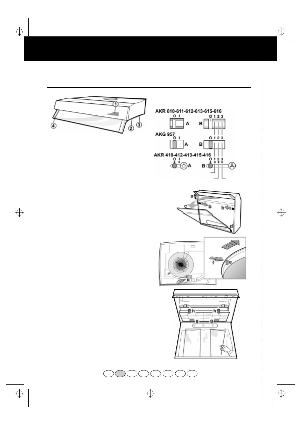
AKR 612-613-615-616 / AKG 957
1. Control panel.
2. Grease filters (behind the extractor grille).
3. Lighting unit.
4. Pull-out steam deflector
(not extractable on AKR 610).
Replacing bulbs
1. Disconnect the electrical power supply.
2. Pull out the steam deflector (a-Fig. 1).
3. Open the extractor grille (b,c,d-Fig. 1).
4. Remove the burnt-out bulb. Replace using 40 W
max E14 bulbs only.
5. Refit the extractor grille.
Fitting or renewing the carbon filter:
1. Disconnect the electrical power supply.
2. Pull out the steam deflector (a-Fig. 1).
3. Open the extractor grille (b,c,d-Fig. 1).
4. Rectangular or circular carbon filter:
Circular carbon filter - Fig. 2:
Fitting: Fit the carbon filter over the motor
protection grille - the reference mark on the edge
of the carbon filter (e) should line up with the
arrow on the fan shroud (f), and turn clockwise.
Removing: turn anti-clockwise.
Rectangular carbon filter - Fig. 3:
Fitting: (g) Locate the carbon filter onto the
rings at the rear and (h) fix at the front by means
of the clips provided.
Removing: press the release buttons
(f-Fig. 2) and pull the filter downwards.
5. Refit the extractor grille.
Removing and renewing or cleaning the
grease filter:
1. Disconnect the electrical power supply.
2. Pull out the steam deflector (a-Fig. 1).
3. Open the extractor grille (b,c,d-Fig. 1).
4. Remove the device securing the grease filter.
5. Remove the dirty grease filter.
6. After the grease filter has been replaced or
cleaned (depending on model), refit the parts in
reverse order, making sure the entire extraction
surface is covered.
CONTROL PANEL
A. Light switch.
B. Speed selector switch.
FIG.1
FIG.2
FIG.3
medium amount of
steam and fumes
large
amount of
steam and
fumes
small amount of steam and fumes
PRODUCT SHEET
F NL E PD GRI
GB
31833009.fm5 Page 4 Wednesday, June 13, 2001 11:35 AM


