Page is loading ...

EasyTouch II Keypad Station
Installation Instructions • Instructions d’Installation • Instrucciones de Instalación
No: IS-0464 – rev. 3 9/23
KS1XXE / KSXXXA • Les Numéros de Catalogue • Los Números de Catálogo:
Country of Origin: Made in China • Pays d’origine: Fabriqué en Chine • País de origen: Hecho en China
OVERVIEW
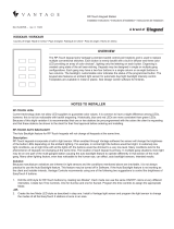
The EasyTouch II keypad joins Vantage’s premiere backlit line of stations. Each button is evenly
backlit with a built in diffuser and three color LEDs providing an array of color choices,* lighting only
the lettering on each button. Keypads may be designed in single or multiple gang congurations.
Individual gangs may have from one to ve buttons in a single column. The backlight color indicates
the status of the programmed button. The keypad also features a built-in ambient light sensor for
automatic day/night backlight intensity control* and an IR receiver. Faceplates are available in metal
or plastic. See InFusion software for nishes.
NOTES TO INSTALLER
EASYTOUCH II 3-COLOR LEDs
Current technology does not allow LED suppliers to guarantee color values. It is common to have a slight difference among LEDs,
however, this is not too noticeable with backlit engraving. Historically, blue and red LEDs are more consistent than green LEDs.
Because of this slight variation it is recommended that one or two stations be pre-programmed with the colors the client is requesting
and that these stations be shown to the client for their nal approval before ordering and installing.
AUTO BACKLIGHT INTENSITY
Issue:
The Auto Backlight feature for EasyTouch II will not change all stations at the same time.
Description:
EasyTouch II stations incorporate a built-in light sensor. When enabled through Vantage software the sensor will change the
brightness of the button LEDs depending on the ambient lighting. For example, in normal light the buttons would be bright. In
extremely low light conditions, as at night time with all the lights off, the buttons would be dimmed to a very low level. Many conditions
lend to the phenomenon of keypads not changing at the same time. The location of each keypad is primary. In multiple gang
situations more light may be on one part of the multi-ganged station causing the auto backlight feature to operate differently in that
section of the multi-gang. Many other lighting factors, even less noticeable to the human eye, can affect, auto backlight sensors,
intended results.
Solution:
Because manufacture variations are inherent in light sensors and the conditions mentioned above are inevitable, it is not always
practical to use the Auto Backlight feature. This feature may be turned off in Software. If the Auto Backlight feature is not working as
the client and installer intends, Vantage Controls recommends using one of the following two suggestions to control the brightness of
EasyTouch II buttons.
1. Edit the LED style for EasyTouch II buttons by creating two Modes*. Each mode can use the same ON/OFF colors at very
different intensities. Create two Time Controls. One for Sunrise and one for Sunset. Program the time controls to assign the
appropriate Mode.
-OR-
2. Create the two Mode LED style as described in step one. Install a Vantage light sensor and program the light sensor to change
the modes of all the EasyTouch II stations at once in an area.

2
No: IS-0464 – Rev. 3
Description Specication
Dimensions, HWD 4.125” x 2.3” x 0.9” (105mm x 58mm x 23mm)
Weight 1.8 oz (51g)
Surge Suppression Weight Yes
Ambient Light Sensor Yes, built-in / standard*
IR Receiver Yes, built-in / standard*
Button LED RGB, Full color
Button Congurations 1 - 5
Status LED Automatic (white = off, orange = on)
Maximum Number of Gangs Up to 4 gangs
Ability to Gang With Conventional Switches Yes (See NEC Code Book for proper installation of Class 2 and Line
Voltage connections)
Sound Yes (Variable pitch)
Addressing Self-addressing through software
Station Bus Connection 24V / 36V Station Bus, no polarity
Station Bus Specications 2C, 16AWG / 1.31mm2, twisted, non-shielded, <30pF per foot. Separate
a minimum of 12” / 30.5cm from other parallel communication and/or
high-voltage runs
Station Wiring Conguration Daisy-chain / Star / Branch
Station Equivalent 24V 3 Buttons count as 0.6 Watts, 5 Buttons count as 0.72 Watts
Station Equivalent 36V 3 Buttons count as 0.9 Watts, 5 Buttons count as 1.08 Watts
Auxiliary Connections 2
Auxiliary WIring Connection 2 Wire 600V Pigtail (Included)
Power For External Devices 15mA @ 12VDC
Outdoor Use - 1 or 2 Gangs Only With approved Weatherproof Cover (Part # WPC-1 or WPC-2)
Ambient Operating Temperature 32-95°F (0-35°C)
Ambient Operating Humidity 5-95% non-condensing
Certications UKCA, CE, UL, cUL
KSX14: EN 55032, EN 55035, EN 61000-3-2, EN 61000-3-3,
EN 62368-1, EN 60065
KSXXXX: EN 55032, EN 55035, EN 61000-3-2, EN 61000-3-3
SPECIFICATIONS
INSTALLATION
NOTE
A one button conguration WILL NOT SUPPORT the built-in ambient light sensor or the IR sensor. When using the Auto Backlight
feature, create a second EasyTouch II keypad style – one with the Auto Backlight feature unchecked for 1-button keypads and
another with the Auto Backlight feature checked for multi-button keypads.
SYSTEM REQUIREMENTS
Equinox 41 is compatible with InFusion Design Center version 3.3 software or higher. For new projects it is recommended that
rmware and software be kept to the most current release.
INSTALLATION REQUIREMENTS
Installation of Vantage products should be performed or supervised by a Certied Vantage Installer. The Vantage Keypad Station
installation is very simple. Connect using the 2 wire pigtail connection located on the rear of the station. It can be mounted into a
standard 1-4 gang electrical box.
CAUTION: The mounting screws must be hand-tightened only, to prevent the station from exing. If the faceplate will not stay on the
station, the mounting screws may be too tight.

3
No: IS-0464 – Rev. 3
AUXILIARY CONNECTIONS
EASYTOUCH II KEYPAD SET UP IN SOFTWARE
All auxiliary connections to the station are wired to a six wire pigtail available from Vantage. Motion detectors, wood and metal door
contacts, light sensors, etc., are available from Vantage. They work by simply connecting them to the 6-wire Auxiliary connector on
the back of the keypad. A 15 mA @ 12V DC power supply for Vantage’s Motion detectors, Light sensors and remote IR is supplied
from this connection eliminating the need for an external power supply. Buttons 9 and 10 may be used as phantom buttons or in
some cases they may be used as slave keypad buttons. NOTE: Secondary keypads are not available with EasyTouch II buttons.
AVOID GROUND LOOPS WITH AUXILIARY
CONNECTIONS
Auxiliary connections to the station are wired to a six wire
pigtail, including motion detectors, door contacts, light
sensors, etc. Each auxiliary connection supplies a 15mA
12V DC power source, eliminating the need for an external
power supply. Auxiliary powered devices using the Black
wire should not be earth grounded unless isolated.
INFUSION
In the Project Explorer click on Style/Prole View. Right- click on Keypad Styles and select Add Keypad Style. In the Object Editor
window ll in all the information for the keypad style including the EasyTouch II Button Shape and select SoftLine or TrimLine.
Remember to check or uncheck the Auto Backlight check box to enable or disable this built-in feature. Right-click on button style and
setup a button style with the button color wanted and backlit buttons. While still in Style/Prole View, right-click on LED Styles and ll
in the appropriate information in the Object Editor for EasyTouch II LEDs – Red/Green/Blue with ON and OFF colors. Next select the
room, then click on Vantage Objects in the Object Explorer and expand Stations, WireLink. From the list of stations double-click on
the Keypad Station to place it in the room. In the Object Editor, name the station and make sure it is on the correct WireLink bus.
CONFIGURATION
When the station is rst connected to the Station Bus, the diagnostic LED will blink twice followed by a pause, meaning that the
station is connected correctly but not yet congured. From Design Center, click on the Congure Stations button on the toolbar.
Highlight the Keypad to be congured. The Status LED will blink 5 times followed by a pause and the button LEDs will blink rapidly
between red and off indicating that the station is in conguration mode. To nish conguring press any button on the Station 3 times.
The station may also be congured by typing the serial number in the project le, using this method the station will automatically be
congured when the system is programmed. Please note, if the serial number contains an alpha character please ignore this when
typing in serial number. Once congured the Status LED will be off and the buttons stop blinking.
DIAGNOSTIC LED INFORMATION
The status LED can be seen behind the sensor light bar which is located between the 3rd and 4th button diffusers. The status LED is
off or blinks 2, 3, 4, or 5 times followed bya pause to indicate status information.
LED STATUS BLINKING PATTERNS
Off: Station is not powered – check that controller is powered and Station Bus connector has power.
Note: if the Station Bus has not been connected or the controller has no power the button LEDs will be off, and the station buttons will
not sound when pressed. If a problem is being diagnosed make sure the Station Bus has power and is properly connected.
One blink: Station is programmed/configured to the system.
Two blinks: Station is operating correctly but is not configured.
Three blinks: Station is not communicating with the main Controller but has power. Verify that Station Bus wiring is correct and that
the station is assigned to the correct Controller.
Four blinks: Station problem, please contact Vantage.
Five blinks: Configuration mode.
Six wire pigtail (ordered separately)
for sensors, dry contacts, etc.

4
No: IS-0464 – Rev. 3
JOINING STATIONS TOGETHER
With the EasyGang station design multiple stations easily snap together to build multi-gang stations.
1. Carefully break off the left, right or both tabs when ganging stations.
NOTE: only break both tabs off on inside stations, with three or more gangs.
2. Align the two stations being joined making sure that UP is the same for both stations.
3. Carefully align locking groves to mesh correctly. Gently press the two halves together until they lock. The joined stations may then
be straightened to secure the lock.
CLEANING
Dampen a soft cloth in water and wring-out to barely damp:
• Use a light bufng motion to wipe clean
• Do not take the station apart
• Never spray station with any cleaners
ASSEMBLY

2.75"
0.9"
4.105"
2.280"
1.75"
1.9"
UP
STAT ION
BUS
Class 2
White LED9 Blue
SW9/IR
Black
GND
Green
SW10/SENSOR
Red
12VDC
15mA
Yellow
LED10
Blue or
Green Black
White or
Yellow Black
Green
Red
Sensor
Black
Blue
Red
IR
Black
Auxiliary Connector Wiring Diagram
COMMERCIAL DIMMER
2K21
No. IS-0464 – rev. 3 9/23
© Copyright 2023 Legrand All Rights Reserved.
© Copyright 2023 Tous droits réservés Legrand.
© Copyright 2023 Legrand Todos los derechos reservados.
Vantage warranties its products to be free of
defects in materials and workmanship for a period
of five (5) years. There are no obligations or
liabilities on the part of Vantage for consequential
damages arising out of, or in connection with,
the use or performance of this product or other
indirect damages with respect to loss of property,
revenue or profit, or cost of removal, installation
or reinstallation.
Vantage garantit que ses produits sont exempts
de défauts de matériaux et de fabrication pour
une période de cinq (5) ans. Vantage ne peut être
tenu responsable de tout dommage consécutif
causé par ou lié à l’utilisation ou à la performance
de ce produit ou tout autre dommage indirect lié
à la perte de propriété, de revenus, ou de profits,
ou aux coûts d’enlèvement, d’installation ou de
réinstallation.
Vantage garantiza que sus productos están libres
de defectos en materiales y mano de obra por un
período de cinco (5) años. No existen obligaciones
ni responsabilidades por parte de Vantage por
daños consecuentes que se deriven o estén
relacionados con el uso o el rendimiento de este
producto u otros daños indirectos con respecto a
la pérdida de propiedad, renta o ganancias, o al
costo de extracción, instalación o reinstalación.
WARRANTY INFORMATION INFORMATIONS RELATIVES À LA GARANTIE INFORMACIÓN DE LA GARANTÍA
800.555.9891
www.legrand.us/vantage
IMPORTANT LED LIGHTING INFORMATION
MULTI-VIEW LINE DRAWING
Vantage is leading the way in LED lighting control through innovations of new hardware and software products; however, industry
standards are still undefined for dimming LED lamps and fixtures. Dimming performance of LED lighting cannot be guaranteed,
even when applying the correct dimming technology specified by the LED manufacturer. While Vantage may be consulted when
performance issues are present, Vantage will not be liable for on-site performance issues. Vantage recommends the following to
assist installers and lighting specifiers:
• Check Vantage’s online library of LED product test reports prior to installing LED products to be dimmed by Vantage dimmers
• Utilize our on-demand product testing of untested LED products - Please contact Vantage for details regarding this service
• Selecting a tested product greatly increases the likelihood of successful dimming; however, LED product tests are performed under
laboratory conditions with a set number of samples and a quality power source
• There are many factors that may contribute to unsatisfactory results within a specific installation, including, but not limited to:
- Line noise originating from electrical equipment within the premises
- Line noise from the source (particularly with local generators or inverters)
- Interference between dimmed LED products
- Wiring conditions (i.e. shared neutrals, loose neutrals, incorrectly bonded neutral, or grounding issues)
- LED product variances, including:
• Unintended batch-related variances
• Product revisions
FRONT VIEW SIDE VIEW BACK VIEW
/
