Page is loading ...

AVT air velocity transmitter
USER GUIDE

Published: 14.11.2023 2 (25)
Contents
1 Introducon............................................................................................................................... 3
1.1 About this user guide............................................................................................................................................................. 3
1.2 Intended use............................................................................................................................................................................. 3
2 Descripon of the product....................................................................................................4
2.1 Overview of the main parts..................................................................................................................................................4
2.2 Technical specificaons.......................................................................................................................................................... 5
2.3 Dimensions................................................................................................................................................................................ 6
3 Safety precauons................................................................................................................... 7
4 Commissioning..........................................................................................................................8
4.1 Warm-up mode........................................................................................................................................................................ 8
4.2 Mounng the product............................................................................................................................................................ 8
4.3 Wiring..........................................................................................................................................................................................9
4.3.1 Modbus models (-MOD)......................................................................................................................................10
4.4 Selecng the measurement range.....................................................................................................................................11
4.5 Selecng the output mode................................................................................................................................................. 11
4.6 Configuring sengs via device menu.............................................................................................................................. 12
4.6.1 Available sengs for velocity and temperature............................................................................................14
4.6.2 Relay sengs......................................................................................................................................................... 16
4.6.3 Exit menu view...................................................................................................................................................... 17
4.7 Available sengs for Modbus........................................................................................................................................... 17
4.7.1 Baud rate menu..................................................................................................................................................... 17
4.7.2 Address menu.........................................................................................................................................................18
4.7.3 Parity bit menu...................................................................................................................................................... 18
4.7.4 Vel. unit menu........................................................................................................................................................18
4.7.5 Temp. unit menu....................................................................................................................................................18
4.7.6 Exit menu view...................................................................................................................................................... 18
4.8 Locking the cover.................................................................................................................................................................. 18
5 Modbus.....................................................................................................................................19
5.1 Terminang Modbus.............................................................................................................................................................19
5.2 Modbus properes................................................................................................................................................................19
5.3 Modbus funcon codes.......................................................................................................................................................19
5.4 Modbus registers...................................................................................................................................................................20
5.4.1 Input registers........................................................................................................................................................ 20
5.4.2 Holding registers....................................................................................................................................................21
6 Maintenance............................................................................................................................23
6.1 Cleaning the probe and the sensor element.................................................................................................................. 23
7 Disposal.................................................................................................................................... 24
8 Warranty policy......................................................................................................................25
Copyright HK Instruments 2023 www.hkinstruments.fi User guide Version 8.2 2023
Informaon is subject to change without prior noce.
EN - 1130100000ug

Published: 14.11.2023 3 (25)
1 Introduction
Thank you for choosing an AVT air velocity transmier. It is an air velocity and temperature transmier. The -MOD
models have Modbus communicaon instead of analogue outputs. Other models have one analogue air velocity output
and one analogue temperature output.
You can select the measurement range and the output mode for the analogue outputs on the field during
commissioning.
The oponal display shows air velocity and temperature measurement values.
The -MOD models have an RS-485 connecon for Modbus RTU communicaon.
The -R model includes a relay and a relay connector.
You can configure the device sengs using:
• the device menu (-D models)
• Modbus communicaon (-MOD models)
1.1 About this user guide
This user guide contains important informaon about the installaon, wiring, configuraon and use of the product.
Read this guide carefully before you install the product, connect the wires, or operate the product. Make sure that you
fully understand all instrucons before you start work. If you are not sure what the instrucons mean, contact the
seller or the manufacturer.
Follow all instrucons in this user guide carefully. Always obey the applicable local rules and regulaons.
The original instrucons were wrien in English. If there are differences between the English instrucons and the
translaons, refer to the English instrucons.
If you find a mistake in the English instrucons or in the translaons, please send the details to the manufacturer.
1.2 Intended use
The AVT air velocity transmiers are intended to be used in commercial environments for measuring air velocity and
temperature in venlaon ducts. They are compable with dry air. The AVT air velocity transmiers are not intended
to be used with flammable or corrosive gases.
These transmiers are intended to be connected to building automaon systems in the HVAC/R industry.
Copyright HK Instruments 2023 www.hkinstruments.fi User guide Version 8.2 2023
Informaon is subject to change without prior noce.
EN - 1130100000ug

Published: 14.11.2023 4 (25)
2 Description of the product
This secon introduces the main parts of the product and contains the technical specificaons.
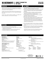
2.1 Overview of the main parts
A
B
C
D
E
F
J
G
H
I
K
A Display (-D models) B Cover
C Cable gland D Strain relief
E Cover locking screw (-R models) F Duct flange
G Probe H Sensor element
I Bolt and nut for locking the probe in posion J Housing
K Holes for fixing screws
Vout/A
24V
GND
NC
COM
NO
Tout/B
Vout/A
24V
GND
Tout/B
S
Q
P
R
L
O
N
M
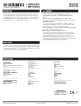
L Menu buons (-D models) M Jumper for temperature output signal selecon
(excluding -MOD models)
N Jumper for air velocity output signal selecon (excluding
-MOD models)
O Terminal block
P Relay (-R models) Q Measurement range selecon jumpers (excluding -D
models)
R Modbus terminaon jumper (-MOD models) S Relay connector (-R models)
Copyright HK Instruments 2023 www.hkinstruments.fi User guide Version 8.2 2023
Informaon is subject to change without prior noce.
EN - 1130100000ug

Published: 14.11.2023 5 (25)
2.2 Technical specifications
Property Value
Supply 24 Vac/dc ± 10 %
Current consumpon max. 80 mA + 40 mA with mA output + 10 mA with relay opon (DC supply voltage)
Relay (-R models) 250 Vac, 6 A res., adjustable operang direcon, switching point and hysteresis
Air velocity measurement
Measurement range 0…2 m/s, 0…10 m/s, 0…20 m/s, freely selectable
Accuracy (typ. at 25 °C) v ≥ 0.15 m/s and ≤ 2 m/s (0.2 m/s + 2 % from reading)
v > 2 m/s and ≤ 10 m/s (0.5 m/s + 3 % from reading)
v > 10 m/s (1.0 m/s + 3 % from reading)
Temperature measurement
Measurement range -25...50 °C (probe)
Accuracy (25 °C) ±0.5 °C (air velocity > 0.5 m/s)
Warm-up me 15 seconds
Outputs
Output signal 1 (T out [C]) 0...10 Vdc, load > 1 kΩ
4...20 mA, load 20…400 Ω
Output signal 2 (v out [m/s]) 0...10 Vdc, load > 1 kΩ
4...20 mA, load 20…400 Ω
Vout:
± 0.025 V at 25 °C
Accuracy
Iout:
typically ±0.04 mA at 25 °C, load 100 Ω
max. ± 0.1 mA at 25 °C, load 20...400 Ω
Relay output (-R models) 3-screw terminal block (NC, COM, NO), potenal free SPDT
30 Vdc 6 A / 230 Vac 6 A res. (IEC 60664-1 OVC II)
Communicaon (MOD models) Modbus RTU
Display (-D models) 2-line display (12 characters/line), 46.0 x 14.5 mm
Line 1: velocity / Line 2: temperature (default)
Line 1: direcon of control output (oponal)
Line 2: relay status (oponal)
Operang condions
Temperature -25...50 °C (probe)
0...50 °C (transmier housing)
Humidity 0...95 %rH (non-condensing)
IP protecon class IP54, cable downwards
Wire 0.2...1.5 mm2 (24...16 AWG)
Cable gland M16 (2 x M16: -R models)
Copyright HK Instruments 2023 www.hkinstruments.fi User guide Version 8.2 2023
Informaon is subject to change without prior noce.
EN - 1130100000ug

Published: 14.11.2023 6 (25)
Property Value
Mounng with a duct flange, probe immersion length adjustable:
50...80 mm (probe length 100 mm)
50...180 mm (probe length 200 mm)
50...380 mm (probe length 400 mm)
Materials
Housing ABS plasc
Cover PC plasc
Probe Stainless steel
Duct flange LLPDP
Dimensions (w x h x d) 86 x 95 x 168 mm (probe length 100 mm)
86 x 95 x 268 mm (probe length 200 mm)
86 x 95 x 468 mm (probe length 400 mm)
Weight 220 g
Storage temperature -20...70 °C
Conformance CE UKCA
EMC 2014/30/EU S.I. 2016 No. 1091
RoHS 2011/65/EU + (EU) 2015/863 S.I. 2012 No. 3032
WEEE 2012/19/EU S.I. 2013 No. 3113
LVD 2014/35/EU S.I. 2016 No. 1101
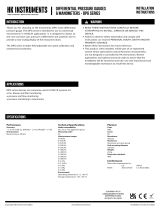
2.3 Dimensions
All dimensions are in millimeters (mm).
71.5
86
95
168 / 268 / 468
46
36
15
17
Copyright HK Instruments 2023 www.hkinstruments.fi User guide Version 8.2 2023
Informaon is subject to change without prior noce.
EN - 1130100000ug

Published: 14.11.2023 7 (25)
3 Safety precautions
The product is developed, manufactured and tested according to high quality standards. However, instrucons for safe
use shall be taken account when installing, using or disposing the product or parts of product.
Read this user guide carefully before commissioning, using or servicing this device. To avoid any kind of damage to
people or property, follow the instrucons carefully. HK Instruments is not liable for any hazards or damages to people
or property which are caused by ignoring the using or installaon instrucons.
To avoid electrical shock or damage to equipment, disconnect power before installing or servicing the product. Use only
a proper wiring rated for the full operang voltage and maximum current in the system even in the event of a fault.
To avoid potenal fire and/or explosion, do not use the product in potenally flammable or explosive atmosphere.
The product condion must be checked before installaon. Do not drop the product or use excessive force during
installaon. Do not use the product if any damages are visible.
Aer installaon the product will be part of a system whose specificaons and performance characteriscs are not
designed or controlled by HK Instruments. Refer to naonal and local authories to ensure that the installaon is
funconal and safe.
The product should only be used in professionally designed applicaons. Unauthorised modificaons are not allowed.
The product must not be used in relaon with any equipment that in case of a failure may threaten, directly or
indirectly, human health or life or result in danger to human beings, animals or property.
In this document, there are different kind of warnings and notes. The warning and note types are defined in the
following table.
Sign Descripon
WARNING: The warning symbol indicates a potenally hazardous situaon which, if not avoided, could result
in death or serious injury.
CAUTION: The cauon symbol indicates a potenally hazardous situaon which, if not avoided, could result
in minor or moderate injury.
Important: The important symbol indicates a potenally hazardous situaon which, if not avoided, could
result in damage to the device or property.
Note: The note symbol indicates a useful p or a recommended way to complete a task. These notes
also provide informaon that is useful but not crical to the user.
Copyright HK Instruments 2023 www.hkinstruments.fi User guide Version 8.2 2023
Informaon is subject to change without prior noce.
EN - 1130100000ug

Published: 14.11.2023 8 (25)
4 Commissioning
4.1 Warm-up mode
This device starts up in warm-up mode. The warm-up mode connues for 15 seconds aer startup. During the warm-
up me, the output signals are at the defined minimum values and the relay does not operate. If the device has a
display, text Warming up is shown on the display. The device starts to operate correctly aer the warm-up me.
4.2 Mounting the product
WARNING: Handle the product with care. Dropping the product may cause internal damage and unwanted
funcons in the connected system.
CAUTION: Place the product outside the reach of children and animals.
Important: The product may only be installed in a locaon where the ambient condions meet the operang
condion requirements.
Note: Remove the device from the air duct before cleaning the duct.
Operang condions
Temperature -25...50 °C (probe)
0...50 °C (transmier housing)
Humidity 0...95 %rH (non-condensing)
1. Check that the product is not damaged during transportaon.
2. Select the mounng posion on a straight duct.
Measure the length of the straight duct to make sure that the probe is posioned correctly. See the figure below
for the required minimum length of straight duct.
• Round ducts:
• D = duct diameter
• Rectangular ducts:
• If there is a horizontal curve or a change in the duct size: D = width of the duct
• If there is a vercal curve or a change in the duct size: D = height of the duct
3. Use the duct flange as a template and mark the screw holes and the probe hole on the duct.
4. Drill the screw holes and the probe hole on the duct.
The maximum screw diameter is 4 mm. The probe diameter is 10 mm.
Copyright HK Instruments 2023 www.hkinstruments.fi User guide Version 8.2 2023
Informaon is subject to change without prior noce.
EN - 1130100000ug

Published: 14.11.2023 9 (25)
5. Mount the duct flange on the duct with screws.
6. Push the transmier probe into the duct through the hole on the flange.
Make sure that the cable glands of the transmier point down. See the figure below for the correct mounng
orientaon.
7. Adjust the probe to the correct depth.
Make sure that the sensor element is in the middle of the duct.
8. Tighten the bolt and nut on the duct flange to hold the probe in posion.
4.3 Wiring
WARNING: Device wiring and commissioning can only be carried out by qualified professionals. Always make
the device wirings in de-energised electricity network.
WARNING: Fuse at load supply (normally 6 A, 10 A, 16 A) does not always limit the relay output load current
to 6 A. The relay maximum load is 250 Vac, 6 A res.
WARNING: Add an external fuse to relay common connector. Use a me-lag fuse (max 6 A) that is in
accordance with the standard IEC 60127-2. The product does not have an internal fuse for the relays.
CAUTION: The product may only be connected to overvoltage category II electricity network according to
IEC 60664-1.
CAUTION: Use single stranded wires or use wire end sleeves if mul stranded wires are used.
For CE and UKCA compliance, a properly grounded shielding cable is required.
The relay models (-R) have two cable glands (the le and the right cable gland). Other models only have one cable gland
(the le cable gland).
1. Open the cover.
WARNING: Do not open the device cover when the relay mains supply voltage is connected. Always do
the commissioning of the device in de-energised relay electricity network.
Copyright HK Instruments 2023 www.hkinstruments.fi User guide Version 8.2 2023
Informaon is subject to change without prior noce.
EN - 1130100000ug

Published: 14.11.2023 10 (25)
2. Unscrew the strain relief on the le cable gland and route the cables for power in and signal out through the cable
gland.
3. For relay models (-R), unscrew the strain relief on the right cable gland and route the cable for the relay through
the cable gland.
4. Connect the wires according to the table below.
Tout/B
Vout/A
24V
GND
NC
COM
NO
Tout/B Temperature measurement output signal:
0...10 Vdc, load > 1 kΩ
4...20 mA, load 20…400 Ω
Vout/A Air velocity measurement output signal:
0...10 Vdc, load > 1 kΩ
4...20 mA, load 20…400 Ω
24V 24 Vac/dc
GND 0 V
NC
COM
NO
Relay output on -R models: 30 Vdc 6 A / 230 Vac 6 A res.
5. Tighten the strain reliefs.
4.3.1 Modbus models (-MOD)
It is recommended to use shielded twisted pair cable for Modbus cabling. The cable shield must be earthed only in one
point, usually at the end of the main cable.
For CE and UKCA compliance, a properly grounded shielding cable is required.
1. Open the cover.
2. Unscrew the strain relief.
3. Route the cables for power in and Modbus communicaon through the cable gland.
Copyright HK Instruments 2023 www.hkinstruments.fi User guide Version 8.2 2023
Informaon is subject to change without prior noce.
EN - 1130100000ug

Published: 14.11.2023 11 (25)
4. Connect the wires according to the table below.
Tout/B
Vout/A
24V
GND
Tout/B
Vout/A
Modbus RTU (RS-485)
24V 24 Vac/dc
GND 0 V
5. Tighten the strain relief.
4.4 Selecting the measurement range
There are different methods for selecng the measurement range. The method used depends on the device opons:
• Devices that do not have a display: Select the measurement range by installing jumpers as shown in the table below.
• Models with display (-D): Select the output signal mode with jumpers and then the measurement range via the
device menu. See secon Selecng the output mode on page 11
Selecting the measurement range with jumpers
Install the jumpers according to the table below to select the measurement range for devices that do not have a display.
Vout/A
24V
GND
Tout/B
J1
J2
mA V
VmA
0...2 m/s 0...10 m/s 0...20 m/s
J1
J2
4.5 Selecting the output mode
Models with analogue output signals have two jumpers for output signal mode selecon on the circuit board. Select the
voltage (0...10 V) or the current (4...20 mA) output signal mode based on the system requirements. The current output
is not scalable. The voltage output is scalable.
Copyright HK Instruments 2023 www.hkinstruments.fi User guide Version 8.2 2023
Informaon is subject to change without prior noce.
EN - 1130100000ug

Published: 14.11.2023 12 (25)
You can configure the output signal separately for air velocity and temperature. Set the jumpers in the correct posion
to select the output signal mode (V/mA) for air velocity and temperature.
See the table below for the jumper sengs.
Vout
Tout
mA V
VmA
Output
Temperature output Tout Output signal
mode: current (mA)
Output signal
mode: voltage (V)
Output signal mode:
current (mA)
Output signal mode:
voltage (V)
Air velocity output Vout Output signal
mode: current (mA)
Output signal
mode: voltage (V)
Output signal mode:
voltage (V)
Output signal mode:
current (mA)
4.6 Configuring settings via device menu
See the figure below for the full menu structure for all models excluding the Modbus models (-MOD). For Modbus
model menu structure, see secon Available sengs for Modbus on page 17.
Copyright HK Instruments 2023 www.hkinstruments.fi User guide Version 8.2 2023
Informaon is subject to change without prior noce.
EN - 1130100000ug

Published: 14.11.2023 13 (25)
PID IN USE
no
V RANGE MAX
10 m/s
REFERENCE SP
5 m/s
NO YES
VEL. UNIT
m/s
TEMP. UNIT
°C
P-VALUE
1.00
I-VALUE
1.00
D-VALUE
1.00
V OUT SCALE
0-10V
V OUT MIN
0 V
Custom
V OUT MAX
10 V
T RANGE MIN
0 °C
T RANGE MAX
50 °C
T OUT SCALE
0-10V
RELAY DIR
Rise
AVT-D-R
RELAY SP
5 m/s
RELAY HYST
0.5 m/s
EXIT MENU
T OUT MIN
0 V
Custom
T OUT MAX
10 V
Copyright HK Instruments 2023 www.hkinstruments.fi User guide Version 8.2 2023
Informaon is subject to change without prior noce.
EN - 1130100000ug

Published: 14.11.2023 14 (25)
Tout/B
Vout/A
24V
GND
A
B
C
A. SELECT buon
B. UP buon
C. DOWN buon
1. Open the cover.
WARNING: Do not open the device cover when the relay mains supply voltage is connected. Always do
the commissioning of the device in de-energised relay electricity network.
2. Press the SELECT buon for two seconds to acvate the device menu.
3. Use the UP and DOWN buons to navigate the menu.
4. Press the SELECT buon to change the value of a menu item.
5. Press the UP or DOWN buon to select a value.
6. Press the SELECT buon to accept the new value and to return to menu navigaon.
7. Navigate to the EXIT MENU view and press the SELECT buon to save the sengs and exit the menu.
4.6.1 Available settings for velocity and temperature
For Modbus model sengs, see chapter Available sengs for Modbus on page 17.
4.6.1.1 Vel. unit menu
You can select the velocity unit for the device display and the velocity output in the VEL. UNIT menu.
The available velocity units are m/s and ft/min. The default value is m/s.
4.6.1.2 Temp. unit menu
You can select the temperature unit for the device display and the temperature output in the TEMP. UNIT menu.
The available temperature units are °C and °F. The default value is °C.
Copyright HK Instruments 2023 www.hkinstruments.fi User guide Version 8.2 2023
Informaon is subject to change without prior noce.
EN - 1130100000ug

Published: 14.11.2023 15 (25)
4.6.1.3 PID in use menu
PID IN USE
no
V RANGE MAX
10 m/s
REFERENCE SP
5 m/s
NO YES
P-VALUE
1.00
I-VALUE
1.00
D-VALUE
1.00
You can select the if PID is in use in the PID IN USE menu.
The available values are no and yes. The default value is no.
If you select no, the next menu item is V RANGE MAX.
If you select yes, the next menu items are REFERENCE SP, P-VALUE, I-VALUE and D-VALUE.
V range max menu
You can select the maximum value for air velocity measurement range in the V RANGE MAX menu.
You can select the maximum velocity measurement range between 1 m/s and 20 m/s. The default value is 10 m/s.
If you selected ft/min in the VEL. UNIT menu, you can select the maximum velocity measurement range between 200
/min and 4000 /min. You can adjust the value by 200 /min steps. The default value is 2000 ft/min.
Reference SP menu
You can select the reference setpoint for the PID controller in the REFERENCE SP menu. You can adjust the value by
0.1 m/s or 1 /min steps depending on the selected air velocity unit. The default value is 5 m/s or 1000 /min.
P-value, I-value and D-value menus
You can select the proporonal gain in the P-value menu. You can adjust the value by 0.01 unit steps. The default value
is 1.00.
You can select the integral gain in the I-value menu. You can adjust the value by 0.01 unit steps. The default value is
1.00.
You can select the derivave gain in the D-value menu. You can adjust the value by 0.01 unit steps. The default value is
1.00.
You can select the P-value, I-value and D-value between 0 and 99.99.
4.6.1.4 V out scale menu
You can select the air velocity output scale in the V OUT SCALE menu.
The available values are 0-5 V, 0-10 V, 2-10 V and custom. The default value is 0-10 V.
If you select custom, you can set the minimum and maximum values for the air velocity output scale.
V out min menu
If you selected custom in the V OUT SCALE menu, you can select the minimum value for the air velocity output scale
in the V OUT MIN menu.
You can select a value between 0 V and 10 V. You can adjust the value by 1 V steps. The default value is 0 V.
You can select a minimum value that is bigger than the maximum value to reverse the operang direcon.
Copyright HK Instruments 2023 www.hkinstruments.fi User guide Version 8.2 2023
Informaon is subject to change without prior noce.
EN - 1130100000ug

Published: 14.11.2023 16 (25)
V out max menu
If you selected custom in the V OUT SCALE menu, you can select the maximum value for the air velocity output scale
in the V OUT MAX menu.
You can select a value between 0 V and 10 V. You can adjust the value by 1 V steps. The default value is 10 V.
You can select a maximum value that is smaller than the minimum value to reverse the operang direcon.
4.6.1.5 T range min menu
You can select the minimum value for temperature measurement range in the T RANGE MIN menu.
You can select a value between -25 °C and 40 °C. You can adjust the value by 5 °C steps. The default value is 0 °C.
If you selected °F in the TEMP. UNIT menu, you can select a value between -13 °F and 104 °F. You can adjust the value
by 2 °F steps. The default value is 32 °F.
4.6.1.6 T range max menu
You can select the maximum value for temperature measurement range in the T RANGE MAX menu.
You can select a value between -15 °C and 50 °C. You can adjust the value by 5 °C steps. The default value is 50 °C.
If you selected °F in the TEMP. UNIT menu, you can select a value between 5 °F and 122 °F. You can adjust the value
by 2 °F steps. The default value is 122 °F.
4.6.1.7 T out scale menu
You can select the temperature output scale in the T OUT SCALE menu.
The available values are 0-5 V, 0-10 V, 2-10 V and custom. The default value is 0-10 V.
If you select custom, you can set the minimum and maximum values for the temperature output scale.
T out min menu
If you selected custom in the T OUT SCALE menu, you can select the minimum value for the temperature output scale
in the T OUT MIN menu.
You can select a value between 0 V and 10 V. You can adjust the value by 1 V steps. The default value is 0 V.
You can select a minimum value that is bigger than the maximum value to reverse the operang direcon.
T out max menu
If you selected custom in the T OUT SCALE menu, you can select the maximum value for the temperature output
scale in the T OUT MAX menu.
You can select a value between 0 V and 10 V. You can adjust the value by 1 V steps. The default value is 10 V.
You can select a maximum value that is smaller than the minimum value to reverse the operang direcon.
4.6.2 Relay settings
RELAY DIR
Rise
RELAY SP
5 m/s
RELAY HYST
0.5 m/s
4.6.2.1 Relay SP menu
This menu is shown only if the transmier has a relay output (-R models).
Copyright HK Instruments 2023 www.hkinstruments.fi User guide Version 8.2 2023
Informaon is subject to change without prior noce.
EN - 1130100000ug

Published: 14.11.2023 17 (25)
You can set the velocity setpoint for the relay in the RELAY SP menu. You can set this value with an accuracy of two
decimals. The default value is 5 m/s or 1000 ft/min.
4.6.2.2 Relay dir menu
This menu is shown only if the transmier has a relay output (-R models). Relay operang direcon defines if the relay
switches on or off when the air velocity is more than the setpoint value.
You can select the relay operang direcon in the RELAY DIR menu. The available values are Rise and Fall. The relay
switches on if Rise is selected and the air velocity is more than the setpoint value. If Fall is selected, the relay switches
on when the air velocity is less than the setpoint value. The default value is Rise.
4.6.2.3 Relay hyst menu
This menu is shown only if the transmier has a relay output (-R models). This seng defines how much the air velocity
must drop below the setpoint before the relay switches off if Rise is selected in the RELAY DIR menu. The funcon is
opposite if Fall is selected in the RELAY DIR menu.
You can set the hysteresis value for the relay in the RELAY HYST menu. You can select a value between 0.1 and 20.0
m/s. You can adjust the value by 0.1 m/s steps. The default value is 0.5 m/s.
If you selected ft/min in the VEL. UNIT menu, you can select a value between 20 /min and 4000 /min. You can
adjust the value by 20 /min steps. The default value is 100 ft/min.
4.6.3 Exit menu view
Navigate to the EXIT MENU view and press the SELECT buon to save the sengs and exit the menu.
4.7 Available settings for Modbus
The figure below shows the menu structure for the Modbus models (-MOD). These menu sengs are only available in
Modbus models (-MOD).
BAUD RATE
19200
ADDRESS
1
PARITY BIT
None
VEL. UNIT
m/s
TEMP. UNIT
°C
EXIT MENU
4.7.1 Baud rate menu
You can select the baud rate in the BAUD RATE menu.
The bus speed can be 9600, 19200 or 38400 bits/s. The default baud rate is 19200 bits/s.
Copyright HK Instruments 2023 www.hkinstruments.fi User guide Version 8.2 2023
Informaon is subject to change without prior noce.
EN - 1130100000ug

Published: 14.11.2023 18 (25)
4.7.2 Address menu
You can select the Modbus address in the ADDRESS menu.
Address range is 1...247. The default value is 1.
4.7.3 Parity bit menu
You can select Modbus parity in the PARITY BIT menu.
The available values for bus parity are none, odd and even. The default seng is none.
4.7.4 Vel. unit menu
You can select the velocity unit for the device display and the velocity output in the VEL. UNIT menu.
The available velocity units are m/s and ft/min. The default value is m/s.
4.7.5 Temp. unit menu
You can select the temperature unit for the device display and the temperature output in the TEMP. UNIT menu.
The available temperature units are °C and °F. The default value is °C.
4.7.6 Exit menu view
Navigate to the EXIT MENU view and press the SELECT buon to save the sengs and exit the menu.
4.8 Locking the cover
WARNING: There is a hazardous voltage inside the R-model devices. Always lock the cover before the relay
mains supply voltage is connected.
1. Close the cover.
2. Tighten the cover locking screw (-R models).
A
A. Cover locking screw
3. Make sure that the cover does not open without tools.
Copyright HK Instruments 2023 www.hkinstruments.fi User guide Version 8.2 2023
Informaon is subject to change without prior noce.
EN - 1130100000ug

Published: 14.11.2023 19 (25)
5 Modbus
5.1 Terminating Modbus
Insert the terminaon jumper in the last device of the network to terminate the Modbus network.
1. Disconnect the device supply voltage.
2. Open the cover.
3. Insert the terminaon jumper in posion (A).
Vout/A
24V
GND
Tout/B
A
4. Close the cover.
5. Reconnect the device supply voltage.
5.2 Modbus properties
The Modbus communicaon is only available in -MOD models.
The parameter memory durability allows at least 1 000 wring cycles.
Note: The changes to the Modbus communicaon sengs take effect aer you restart the device.
Protocol RS-485 Modbus RTU
Bus speed 9600/19200*/38400 bit/s
Data bits 8
Parity none*/odd/even
Stop bits 1
Modbus ID 1*
Unit load 1/8 UL
* factory seng
5.3 Modbus function codes
The device supports the following Modbus funcon codes.
Decimal HexadecimalFuncon
3 0x03 Read Holding Registers
4 0x04 Read Input Registers
6 0x06 Write Single Register
16 0x10 Write Mulple Registers
Copyright HK Instruments 2023 www.hkinstruments.fi User guide Version 8.2 2023
Informaon is subject to change without prior noce.
EN - 1130100000ug

Published: 14.11.2023 20 (25)
5.4 Modbus registers
5.4.1 Input registers
General
Register Parameter descripon Data type Values Range
0Velocity m/s U16 0...2000 0...20 m/s
1Velocity /min U16 0...4000 0...4000 /min
2Temperature °C S16 -250…500 -25.0…50.0 °C
3Temperature °F S16 -130…1220 -13.0…122.0 °F
4...99 Reserved for future use
Device model details
Register Parameter descripon Data type Values Range
9800 Register count U16 0...99 0…99
9801 Format version U16 0…65535 0…65535
9802 Display U16 0...1 0. no
1. yes
9803 Buons U16 0...1 0. no
1. yes
9804 Number of relays U16 0...1 0....1
9805 Analogue outputs U16 0...1 0. no
1. yes
9806 Modbus U16 0...1 0. no
1. yes
9807 MyTool Connector U16 0...1 0. no
1. yes
9808 PID controller U16 0...1 0. no
1. yes
Device information
Register Parameter descripon Data type Values Range
9900 Device type U16 0…65535 0…65535
9901 Hardware version U16 0…65535 0…65535
9902 Producon number, MS word U16 0…65535 0…65535
9903 Producon number, LS word U16 0…65535 0…65535
9904 Configuraon number, MS word U16 0…65535 0…65535
9905 Configuraon number, LS word U16 0…65535 0…65535
9906...9908 Reserved for MyTool®U16
9909 Ethernet MAC address 1 U16 00
9910 Ethernet MAC address 2 U16 00
9911 Ethernet MAC address 3 U16 00
9912 Wireless MAC address 1 U16 00
Copyright HK Instruments 2023 www.hkinstruments.fi User guide Version 8.2 2023
Informaon is subject to change without prior noce.
EN - 1130100000ug
/