Dwyer Instruments AVUL-3DA1-LCD User manual

Type
User manual

Dwyer Instruments AVUL-3DA1-LCD is a versatile device that measures air velocity or volumetric flow in imperial or metric units. It offers:

  • Easy monitoring with optional integral display or portable remote display tool.
  • Simultaneous current and voltage outputs for universal compatibility.
  • Configurable output range, units, and 0-5/10 VDC output via local DIP switches.
  • High accuracy with ±(3% of reading + 0.2 m/s) @ standard conditions.
  • Range selection for 1000, 2000, 3000, or 4000 FPM (5, 10, 15, or 20 m/s).
Series AVUL Air Velocity Transmitter with BACnet Communication
Specications - Installation and Operating Instructions
Bulletin P-AVUL-B
The Series AVUL Air Velocity Transmitter quickly and accurately measures air
velocity or volumetric ow in imperial or metric units. Simultaneous current and voltage
outputs on all models provide universal inputs to monitoring equipment while the
output range, units, and 0-5/10 VDC output can be congured via local DIP switches.
The optional integral display, or the portable remote display tool, provide a convenient
way to locally monitor process values and congure the unit.
Models are available in 3% and 5% of reading accuracy models to suit a variety
of needs, and the optional BACnet MS/TP or Modbus® RTU/ASCII communication
protocol allows units to be daisy-chained while providing access to all of the velocity
and ow data, as well as additional information such as air temperature.
SPECIFICATIONS
Service: Clean air and non-combustible, compatible gases.
Wetted Materials: Consult factory.
Range: 1000, 2000, 3000, 4000 FPM (5, 10, 15, 20 m/s); Field selectable.
Accuracy: ±(5% of reading + 0.2 m/s) or ±(3% of reading + 0.2 m/s) @ standard
conditions, depending on model.
Temperature Limits: 32 to 122°F (0 to 50°C).
Power Requirements: 24 VDC ±20% or 24 VAC ±20%.
Humidity Limits: 5 to 95% RH, non-condensing.
Output Signals: 4-20 mA, 0-5 VDC, 0-10 VDC.
Response Time (90%): 10 s, typical.
Zero and Span Adjustments: Digital push buttons.
Output Load Resistance: Current output: 0 to 1100 Ω max.; Voltage output:
Minimum load resistance 1 kΩ.
Current Consumption: 60 mA max.
Display (Optional): 5 digit LCD.
Electrical Connections (Analog): Power and output: 4-wire removable European
style terminal block for 16 to 26 AWG.
Communication (Optional): Connections: BACnet MS/TP or Modbus® RTU/ASCII:
3-wire removable European style terminal block for 16 to 26 AWG; Supported baud
rates: 9600, 19200, 38400, 57600, 76800, 115200.
Device Load: 1/8 unit load.
Electrical Entry: 1/2˝ NPS thread. Accessory (A-151): Cable gland for 5 to 10 mm
diameter cable.
Enclosure Rating: NEMA 4X (IP66).
Mounting Orientation: Flow direction must be parallel to the sensor tip;
See Installation section for details.
Weight: 6.0 oz (160 g).
Compliance: CE.
DWYER INSTRUMENTS, LLC
P.O. BOX 373 • MICHIGAN CITY, INDIANA 46360, U.S.A.
Phone: 219-879-8000
Fax: 219-872-9057
www.dwyer-inst.com
1/2 NPS
2-43/64
[67.92]
3-49/64
[95.71]
3-3/16
[80.81]
31/32 [24.58
]
1-19/32
[40.59]
2-5/32
[54.82]
7-41/64
[194.07]
3-33/64
[89.13]
7-17/64
[184.60]
39/64
[15.32]
Ø15/32
[11.84]
®
MODEL CHART
Model AVUL -3 D A1 -LCD AVUL-3DA1-LCD
Accuracy 5
3
±(0.2 m/s + 5% of reading) @ standard
conditions
±(0.2 m/s + 3% of reading) @ standard
conditions
Mounting D Duct mount
Output A1
B1
M1
Analog universal (0-5 VDC, 0-10 VDC, 4-20
mA)
Analog + BACnet MS/TP
Analog + Modbus® RTU/ASCII
Options LCD
FC
NIST
GLD
SF
LCD display
Factory calibration certicate
NIST certicate
Electrical cable gland
Silicone free
INSTALLATION
Duct Mount:
The transmitter should be mounted away from fans, corners, heating and cooling
coils, and other equipment that will effect the measurement of the air velocity. It
is recommended that the AVUL is mounted 10 duct diameters downstream of any
disturbances and 5 duct diameters upstream of any disturbances, if possible.
1. Mark and drill a 0.750 to 0.938˝ (20 to 24 mm) diameter hole into the duct.
2. Insert and center the duct mount ange in the previously drilled hole and mark
location of the three mounting screw holes.
3. Remove the mounting ange and drill or punch the mounting holes in the marked
locations.
4. Fasten the ange to the duct using three #8 x 1/2 pan head sheet metal screws. Do
not over tighten screws.
5. Insert the AVUL probe into the ducts mount ange and set the desired insertion
depth.
6. Note the ow direction and unit alignment as shown on sensor tip and product label,
tighten probe retention set screw on the duct mount ange screw to afx the probe
in place.
Electrical Connection:
The Series AVUL is powered and simultaneously transmits a 2-wire 4-20 mA current
output and a three-wire 0-5 VDC or 0-10 VDC voltage output via a removable four
conductor terminal block. The transmitter power supply common is used to reference
the current and voltage outputs so either current, voltage, or current and voltage may
be wired according to the application. The range of the voltage output can be selected
using the on board DIP switches as described in the Analog DIP Switch Settings
section of this manual.
Power Supply
Choose a power supply with a voltage and current rating sufcient to meet the power
specications under all operating conditions. If the power supply is unregulated, make
sure the output voltage remains within the required voltage range under all power line
conditions. Ripple on the supply should not exceed 100 mV.
Current Output Operation
The terminal block is removable, and each of the terminals are labeled underneath
the terminal block on the circuit board. As the power supply and outputs share the
same common signal (GND), the outputs may have separate wires but must effectively
join at terminal 2 of the transmitter, as shown in Figure 1. The connections to the
transmitter are made to terminals 1, 2, and 3 (PWR, GND, and IOUT respectively) on
the terminal block as shown in Figure 4.
Figure 1: Current output wiring
Although low loop resistances are recommended, the absolute maximum current loop
load resistance, RMAX , is dened by the following the equation:
RMAX = where VPS is the power supply voltage
For a 24 VDC nominal power supply, this evaluates to RMAX = 1100 ohms.
Shielded two wire cable is recommended for current output loop wiring. Ground the
shield at the power supply end only.
The maximum length of connecting wire between the current transmitter and the
receiver is a function of wire size and receiver resistance. That portion of the total
current loop resistance represented by the resistance of the connecting wires
themselves should not exceed 10% of the receiver resistance. For extremely long
runs (over 1,000 ft.), it is desirable to select receivers with higher resistances in order
to keep the size and cost of the connecting leads as low as possible. In installations
where the connecting run is no more than 100 ft, connecting lead wire as small as No.
22 Ga. can be used.
Voltage Output Operation
The terminal block is removable, and each of the terminals are labeled underneath the
terminal block on the circuit board. The voltage output and the power supply must have
separate wire leads that are only joined at terminal 2 of the transmitter, as shown in
Figure 2. Additional error may occur for the voltage output if a single wire is used or if
the wires are joined at the power supply or receiver. The connections to the transmitter
are made to terminals 1, 2, and 4 (PWR, GND, and VOUT respectively) on the terminal
block as shown in Figure 4.
The minimum receiver load is 1 kΩ. The resistance due to the wire should be low
compared to the receiver load resistance. While the voltage at the terminal block
remains unchanged with a 10 mA current ow, resistive losses in the wiring do cause
errors in the voltage delivered to the receiver. For a 1% accurate gauge, the resistance
of the wires should be less than 0.1% of the value of the receiver load resistance. This
will keep the error caused by the current ow below 0.1%.
The output across VOUT and COM will be either 0-5 VDC, 0-10 VDC, or the inverse
depending on the DIP switch setting. See the Analog DIP Switch Settings section for
more information.
Figure 2: Voltage output wiring
POWER CURRENT
RECEIVER
ZERO
PWR
GND
IOUT
VOUT
D1 [+]
D1 [-]
COM
1
SW1
234 SPAN
VOLTAGE
RECEIVER
POWER
PWR
GND
IOUT
VOUT
D1 [+]
D1 [-]
COM
SPAN
12
34
SW1
ZERO
(VPS – 2.0)
0.02
DO NOT EXCEED SPECIFIED SUPPLY VOLTAGE RATINGS.
PERMANENT DAMAGE NOT COVERED BY WARRANTY WILL
RESULT.
DO NOT EXCEED SPECIFIED SUPPLY VOLTAGE RATINGS.
PERMANENT DAMAGE NOT COVERED BY WARRANTY WILL
RESULT.
CAUTION
CAUTION
DO NOT EXCEED SPECIFIED SUPPLY VOLTAGE RATINGS.
PERMANENT DAMAGE NOT COVERED BY WARRANTY WILL
RESULT.
CAUTION
Simultaneous Current and Voltage Output Operation
The terminal block is removable, and each of the terminals are labeled underneath the
terminal block on the circuit board. The voltage output and the power supply must have
separate wire leads that are only joined at terminal 2 of the transmitter, as shown in
Figure 3. Additional error may occur for the voltage output if a single wire is used or if
the wires are joined at the power supply or receiver. The connections to the transmitter
are made to terminals 1, 2, 3 and 4 (PWR, GND, IOUT, and VOUT respectively) on
the terminal block as shown in Figure 4, which reects both the 4-20 mA and 0-5/10
VDC outputs in the same circuit. Details of each output are detailed in their electrical
connection sections.
ANALOG DIP SWITCH SETTINGS
The analog output DIP switches (SW1) are located above the terminal blocks on the
left are as shown in Figure 4. A small screw driver or pen can be used to change
the position of the switches as required. DIP switch positions for SW2 and SW3 are
RESERVED or have no affect.
Factory Default Settings (DIP SW1 – All Switches ON)
Range = Highest Range Setting (4000 FPM)
Units = Imperial (FPM)
Voltage Output Range = 0-10 VDC
Direct / Reverse Output Action = Direct
Setting the Air Velocity Range
The range of the instrument is selected by using DIP switches 1 and 2 on SW1. Table
1 shows the maximum full scale value for the selected range and unit. Refer to Setting
the Engineering Units section for information on setting the unit.
Setting the Engineering Units
The Series AVUL can be congured to indicate velocity in imperial (FPM, CFM) or
metric (m/s, m3/h) units using DIP switches 4 and 5 on SW1, and Table 2 shows the
values. The units will be displayed on the optional LCD display if connected.
The default operating mode is velocity, but changes can be made, such as ow
mode, via the menu system while an optional display or remote display accessory is
connected. Please refer to Appendix III for a full menu ow chart.
Setting the Output Voltage Range
Voltage Output can be either 0-5 VDC or 0-10 VDC depending on the position of DIP
Switch 6 ON SW1.
When the switch is in the ON position, the output will be 0-10 VDC.
When the switch is in the OFF position, the output will be 0-5 VDC.
Setting the Input / Output Action
The output will either follow the process directly (DIRECT) or inverted (REVERSED)
based on the position of DIP Switch 7 on SW1.
When the switch is in the ON position, the output directly follows the input (i.e. output
increases as the input increases).
When the switch is in the OFF position, the output acts in reverse of the input (i.e.
output decreases as the input increases).
Table 1: DIP switch SW1 settings for full-scale range
Table 2: DIP switch SW1 settings for units
Figure 4: Analog DIP switches
Figure 3: Simultaneous current and voltage output wiring
POWER
CURRENT
RECEIVER
VOLTAGE
RECEIVER
ZERO
PWR
GND
IOUT
VOUT
D1 [+]
D1 [-]
COM
1
SW1
234 SPAN
DIR
10 V
UNITS
RANG
E
KEY
ZERO
PWR
GND
IOUT
VOUT
D1 [+]
D1 [-]
COM
1
SW1
234 SPAN
5 V
REV
SW1
DIP Switch SW1 Full Scale Range
1 2 Imperial (FPM) Metric (m/s)
ON
ON
OFF
OFF
ON
OFF
ON
OFF
4000
3000
2000
1000
20
15
10
5
DIP Switch SW1 Units
4 5 Velocity Mode Air Flow Mode
ON
ON
OFF
OFF
ON
OFF
ON
OFF
FPM
m/s
m/s
m/s
CFM
m3/h
m3/h
m3/h
DO NOT EXCEED SPECIFIED SUPPLY VOLTAGE RATINGS.
PERMANENT DAMAGE NOT COVERED BY WARRANTY WILL
RESULT.
CAUTION
All power should be turned off to the transmitter before adjusting
the DIP switch settings to avoid electrical shock.
WARNING
CALIBRATION
Zero Calibration
The zero calibration can be set by covering the sensor to ensure no air ow and
pressing the zero button for 3 seconds. If either the remote or local LCD is present, the
display will read ZEro and then sequence back to the home display.
SPAN Calibration
The span calibration can be adjusted only after setting the zero adjustment. It must
be completed within 5 minutes of the last zero calibration. The span calibration button
will be ignored until the zero calibration is completed. Place the sensor in airow that
matches the maximum selected range of the transmitter. Press and hold the span
button for 3 seconds. If either the remote or local LCD is present, the display will read
SPAn and then sequence back to the home display. If the span calibration is attempted
before adjusting the zero calibration, the FAiL error message will be displayed briey
before returning to the home display.
LCD Display
The Series AVUL can be ordered with an optional, integral LCD. It comes with a
housing cover and overlay to protect the display. The display will plug into the pins as
shown in Figure 5. If the display is not needed for normal operation, the transmitter can
be ordered without the LCD.
Another option for models that do not have a display would be to use a Model A-435-A
remote display tool which can plug into the connector shown in Figure 6. The remote
display tool has two buttons that function identically to the buttons on the PCB.
Display Error Messages
ovEr = The air velocity is greater than the maximum span value causing an Over
Range Error
UndEr = The air velocity is less than the minimum span value causing an Under Range
Error
FAiL = When the span or zero buttons are pressed, the air velocity value is out of the
range to allow a correct setting. This may be due to a sensor failure.
Err1 = The sensor is damaged.
PROGRAMMING MENUS
Home Menu
During normal operation, the display will be in the Home Menu and will display the
current measured pressure and the engineering units.
Menu Access Security
While in the Home Menu, press and hold the Zero and Span buttons simultaneously
until SECUr appears on the display in order to access the other programming menus.
Upon releasing the buttons, the display will indicate the current security level.
If the current security level is the security level desired (i.e. Security Level 0), press
and hold the span button for 3 seconds to enter the Velocity or Air Flow Menu.
If the security level is not the desired level, the security level can be changed
temporarily to a lower security level or permanently to a higher level of security by
pressing the zero button. A security code will appear on the display, and it can be
changed to one of the codes listed in Table 3. The span button chooses which digit
and the zero button increments the value of that digit. Pressing and holding the span
button will store the value.
The level of access to the programming menus and the calibration is limited based on
the security level. Table 3 details the level of access for each security level.
Figure 5: Pluggable display diagram
Figure 6: Remote display diagram
ZERO
PWR
GND
IOUT
VOUT
D1 [+]
D1 [-]
COM
SW1
SPAN
ZERO
PWR
GND
IOUT
VOUT
D1 [+]
D1 [-]
COM
1
SW1
234SPAN
There is a 5 second delay from the time the zero or span calibration
buttons are released until the time that the change in calibration
takes place. This delay is used to reduce vibration or disturbances of the user related
to the button presses.
The security level that is set in the Programming Menu section
of the manual will determine which calibrations, if any, may be
adjusted by the user.
NOTICE
NOTICE
Mode Selection / Digital Dampening Menu
From the home display, pressing the span and zero button simultaneously for 3
seconds will access the Menu Security Level. If the level is set to 0 or 1, pressing and
holding the span button for 3 seconds, a second time, will access the Mode Selection
Menu. The display will default to air velocity when rst powered up. Pressing the zero
button will cycle to air ow.
Once the desired mode is displayed, pressing and holding the span button for 3
seconds will save the selected mode and display the digital dampening or averaging
parameter. This parameter stabilizes the output and the display by averaging the
readings. There are 2.5 readings taken each second and the user can select the
number of seconds that they would like to average, up to 240 seconds. The display
and the output will continue to update at a rate of 2.5 updates per second, but the
moving average is used for these updates.
Velocity Mode
K-Factor Adjustment
If the Velocity Mode was selected, pressing and holding the span after adjusting the
digital dampening will enter the Velocity Mode and the transmitter will display the
engineering unit that has been selected by the DIP switch. Pressing and holding the
span button for 3 seconds will enter the K Factor adjustment. The K Factor can
be adjusted between 0.001 to 9.999. The K-Factor can be adjusted by pressing the
span button to select the digit and pressing the zero button to increment the value of
the digit. Pressing and holding the span button for 3 seconds will enter the Maximum
Output Adjustment parameter.
Flow Mode
K-Factor Adjustment
If the Flow Mode was selected, pressing and holding the span after adjusting the digital
dampening will enter the Flow Mode and the transmitter will display the engineering
unit that has been selected by the DIP switch. Pressing and holding the span button for
3 seconds will enter the K–Factor adjustment. The K–Factor can be adjusted between
0.001 to 9.999. The K-Factor can be adjusted by pressing the span button to select
the digit and pressing the zero button to increment the value of the digit. Pressing and
holding the span button for 3 seconds will enter the Area Adjustment parameter.
Area Adjustment
For ow applications, the area is multiplied by the velocity to determine the volumetric
air ow. The area will be listed in either CFM or m3/h depending on the DIP switch
settings. The units will appear on the display at the time of adjustment. The area can
be adjusted by pressing the span button to select the digit and pressing the zero button
to increment the value of the digit. Pressing and holding the span button for 3 seconds
will enter the Maximum Output Adjustment parameter.
Maximum Output Adjustment
The maximum output can be equivalent to air velocity or air ow. After adjusting
the K-Factor, the display will indicate if the adjustment is set for velocity or air ow.
Pressing the zero button will toggle between the selections. Pressing and holding the
span button for 3 seconds will enter the maximum output adjustment. The maximum
output can be adjusted by pressing the span button to select the digit and pressing the
zero button to increment the value of the digit. Pressing and holding the span button
for 3 seconds will save this value and go to the Security Update Menu.
Security Update / Save Changes Menu
The Security Update Menu allows the security level to be set either higher or lower
than the current security level setting. This security level will be displayed the next
time the Menus are accessed from the home screen. Pressing the zero button cycles
through the security levels. Pressing and holding the span button for 3 seconds
accepts the new security level and gives the option to save all the menu changes.
Pressing the zero button will toggle between yes and no. Yes will save the changes
made to all menu items and no will discard all the changes made to all menu items. If
the display is set to yes, pressing and holding the span will save the menu items and
return the display to the home position.
FACTORY DEFAULT PROCEDURE
In order to reset all of the menu settings back to their factory programmed values,
press and hold both the span and zero buttons simultaneously for 10 seconds until
FACt is displayed on the LCD. Upon releasing the buttons, the unit will be factory
defaulted. Since resetting the transmitter will wipe out all changes, it is necessary to
zero (and possibly span) the transmitter before taking measurements.
MAINTENANCE/REPAIR
Upon nal installation of the Series AVUL Air Velocity Transmitter, no routine
maintenance is required besides zeroing the transmitter occasionally. Besides routine
calibration and installation of the LCD, the Series AVUL is not eld serviceable, and
it is not possible to repair the unit. Field repair should not be attempted and may void
warranty.
WARRANTY/RETURN
Refer to “Terms and Conditions of Sales” in our catalog and on our website. Contact
customer service to receive a Return Goods Authorization number before shipping the
product back for repair. Be sure to include a brief description of the problem plus any
additional application notes.
APPENDIX I: Air Velocity / Air Flow Calculations
Velocity in m/s is then calculated from the equation:
Velocity (m/s) = Velocity (FPM) x 0.00508
Flow in m3/h is then calculated using the below equation:
Flow (CFM) = Area (ft2) x K-Factor x Velocity (FPM)
Flow (m3/h) = Flow (CFM) x 1.6992
APPENDIX II: Maximum Flow
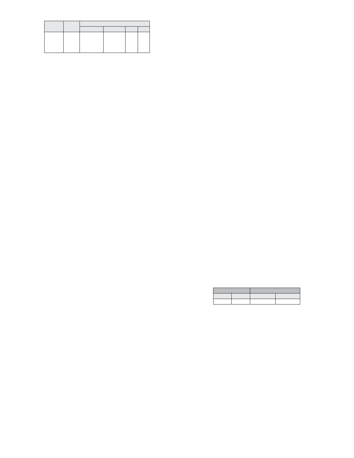
Table 3: Security settings
Table 4: Maximum ow values
Max Flow Max K Factor x Area
CFM m3/h CFM Range m3/h Range
5885000 9999000 1471.25 138.875
Security
Level Setting
Access
View Menu Edit Menu Span Zero
0
1
2
3
000
111
222
333
Yes
Yes
No
No
Yes
No
No
No
Yes
No
No
No
Yes
Yes
No
No
PWR GND IOUT VOUT
TO
NEXT
DEVICE
D1[+]
D0[-]
PWR
COM
D1[+]
D0[-]
PWR
COM
TO
PREVIOUS
DEVICE
D1[+] D0[-]COM
D1[+]
D0[-]
CO
M
D1[+]
D0[-]
COM
POWER
SUPPLY
+ -
PWR GND IOUT VOUT D1[+] D0[-]COM
BACnet MS/TP DIP Switch Settings
Use the middle DIP Switch SW2 to congure the BACnet MS/TP MAC communication
protocol address of the device. The LCD will show the address when the transmitter
is powered on. Valid addresses range from 0 to 127. By default, the device is shipped
with the address 127 (as shown in Figure 10). A valid and unused address should
be set before connecting to an existing network. However, the address can be
changed while the device is operational. If the address is changed, the device will
stop responding to the currently congured address immediately. The device waits
15 seconds after the last switch change before applying the new address. The device
will not function properly if an invalid address is set. The red LED will periodically blink
once indicating an invalid address. The LCD will display A Err when the transmitter
is powered on if the address is invalid. See Appendix V for setting the BACnet MS/TP
MAC address of the device. Use the right DIP Switch SW3 to congure other hardware
and software options.
APPENDIX III: BACnet MS/TP Operation
Figure 7 shows how to connect the AVUL in a network containing a common power
supply. Use a cable containing two twisted pairs. One pair is to be used for D1[+]
and D0[-]. The other pair is to be used for power and common. This conguration is
not suitable for AC supplies. Use a DC supply only. Care should be taken that there
are not too many devices powered from the same supply as voltage drops will occur
in the wiring. If you have many devices, or have long cable runs, the local supply
conguration may be a better choice.
Figure 8 shows how to connect the AVUL in a network containing individual local
supplies. Use a cable containing a twisted pair and a single conductor. The pair is to
be used for D1[+] and D0[-]. The single conductor is to be used for common. Both AC
and DC supplies are suitable for this conguration.
In either conguration you must use shielded cable. The AVUL has a shield terminal
for a convenient location to make connections. It is not electrically connected to the
AVUL. Connect the shield to earth ground at one location only to prevent ground loops.
All devices in the network should be daisy chained. Star connections and T connections
are not permitted.
The D1[+] and D0[-] lines must be terminated at both ends with a 120 Ω resistor. If the
AVUL is an end device it has an on-board resistor that may be used. See BACnet MS/
TP DIP Switch Settings to enable it.
The network must be biased properly. If needed, there are bias resistors on-board the
AVUL. No more than two sets of bias resistors should be enabled in the network. See
BACnet DIP Switch Settings to enable them.
SW3
SW2
KEY:
128 - MSB 64
32 16
84
21 - LSB
BACNET RESET
CONFIGURA
TION
SW1
ZERO SPAN
SW2 SW3
TERMINATING
RESISTOR
BIAS
RESISTOR
Figure 9
Switch On Off
1-2 – Display Units Selection
3-4 – Reserved
5 - Reset BACnet
Conguration to Factory
Defaults
6 – D1[+] Network Resistor
7 – D0[-] Network Resistor
8 – Terminating resistor
Reset settings at Power
On
511Ω Pull-up to 5 V
511Ω Pull-down to GND
120Ω between D0[-] and
D1[+]
Settings Preserved
Pull-up not connected
Pull-down not connected
Open
Table 5: DIP switch SW3 functions
Wiring should comply with Electrical Characteristics of Generators
and Receivers for Use in Balanced Digital Multipoint Systems, TIA/
EIA-485-A-1998, Telecommunications Industry Association, 1998.
Communications wiring must be in a daisy-chain fashion. Star
connections are not permitted.
Wiring should comply with ANSI/ASHRAE Standard 135-2010
BACnet A Data Communication Protocol for Building Automation
and Control Networks, American Society of Heating, Refrigerating and Air-Conditioning
Engineers, Inc., 2010.
Cable shield must be connected to earth ground at one location
only.
NOTICE
NOTICE
NOTICE
NOTICE
Figure 7: Common power supply
Figure 8: Local power supply
APPENDIX IV: Programming Via BACnet MS/TP Communication Protocol
Auto-Baud Serial Conguration
Auto-baud serial conguration enables the device to determine the baud rate directly
from the serial trafc. This allows a device to be quickly and easily deployed after a
valid BACnet Communication Protocol MS/TP address is chosen.
To activate auto-baud serial conguration, set a valid BACnet Communication Protocol
MS/TP address using the left DIP switch SW2, connect the serial bus and power wires,
and then apply power. The device will power up and begin examining the serial bus
for communication. The Red LED will repeatedly ash twice, indicating that auto-baud
serial conguration is in progress.
If the device is setup ofine or away from the main network, it is necessary to generate
BACnet Communication Protocol MS/TP trafc in order to congure the serial
communication. Initiating a WhoIs command is a good method to generate BACnet
Communication Protocol MS/TP trafc and verify the device is working properly. Note
that while serial conguration is in progress, the device may not respond to requests.
The device may require multiple requests to complete the serial conguration process.
The auto-baud serial conguration process will complete once a WhoIs or
ReadProperty command is successfully received and processed.
The auto-baud serial conguration procedure is started after a power-cycle and after
a change to the MS/TP address.
BACnet MS/TP Communication Protocol Object Overview
Supported Baud Rates Data Size Parity Stop Bits
9600
19200
38400
57600
76800
115200
8 None 1
Table 6: Supported BACnet communication protocol
MS/TP congurations
Object Type
Dynamically
Creatable
Dynamically
Deletable
Object
Identier Object Name
Device
Analog Input
Analog Value
Binary Value
No
No
No
No
No
No
No
No
607xxx
AI1
AI2
AI3
AI4
AV1
AV2
AV3
AV4
BV1
BV2
BV3
AVUL Velocity
Velocity FPM
Velocity MPS
Temperature F
Temperature C
Flow CFM
Flow CMH
Flow Area SqFt
Flow Area SqM
Zero
Span
Restore Factory
Pressure Values
Table 7: Supported BACnet MS/TP Communication Protocol Objects
Device Information
The default device object identier is 607xxx, where xxx is replaced by the MS/TP
MAC address set by the middle DIP switch SW2. The object identier value will change
as the MS/TP MAC address changes. However, if a specic object identier is written
via BACnet MS/TP Communication Protocol, then that value is stored and changes to
the MS/TP MAC address will no longer affect the object identier. See Appendix VI for
the device object property tables.
Accessing the Measurements
The analog input object AI1 through AI4 are for viewing Air Velocity or Temperature in
the desired engineering units. The object property tables for these analog input objects
can be found in Appendix VI.
Analog value object AV1 through AV4 are for viewing the Air Flow or Flow Area
calculated values in the desired engineering units. The object property tables for the
analog value objects can be found in Appendix VI.
Zero Calibration
Zero calibration can be done either with the push buttons or using BACnet MS/TP
communications. The unit should have no air owing through it. When using BACnet
MS/TP communications, the binary value object (BV1) will be used to signal the
transmitter to zero the reading. The present value of this object will be set to ACTIVE
(1) to initiate the re-calibration of the zero point of the sensor. The zero function will
only work if the current velocity is within ±2% of the span velocity of the previous zero.
If the current velocity is outside of this valid band, the zero function will fail and the
present value will be changed to INACTIVE (0). The zero function takes at most 10
seconds to complete. If after this time the present value remains ACTIVE (1), then the
command was executed successfully. The object property tables for the binary value
objects can be found in Appendix VI.
Span Calibration
In order to adjust the span calibration, place the unit in a ow with air velocity that is
associated with the maximum end of the transmitter range. The binary value object
(BV2) will be used to signal the transmitter to adjust span. The present value will be
set to ACTIVE (1) to initiate the span calibration. The span calibration can be adjusted
only after setting the zero adjustment. It must be completed within 5 minutes of the
last zero calibration. The span calibration command will fail until the zero calibration is
completed and the present value will be returned to INACTIVE (0). The span function
takes at most 10 seconds to complete. If after this time, the present value remains
ACTIVE (1), then the command was executed successfully. The object property tables
for the binary value objects can be found in Appendix VI.
Reset factory Defaults
Present values for the zero, span, and area can be restored to the factory settings
using the binary value object (BV3). The present value will be set to ACTIVE (1) to
initiate the factory default procedure. The factory default takes at most 10 seconds to
complete. If after this time, the present value remains ACTIVE (1), then the command
was executed successfully. The object property tables for the binary value objects can
be found in Appendix VI.
BACnet MS/TP Communication Protocol Services
Device Communication Control Service (DM-DCC-B)
This device supports the Device Communication Control Service BIBB. The optional
time duration in minutes is also supported. This device is congured with a password
that must be provided to successfully execute this command. The password is “Dwyer”.
Reinitialize Device Service (DM-RD-B)
This device supports the Reinitialize Device Service BIBB. The supported device
states are COLDSTART and WARMSTART. All other states return error. This device
is congured with a password that must be provided to successfully execute this
command. The password is “Dwyer”.
Changes to Max Master and Max Info frames require a power
cycle/reset to take effect.
NOTICE
APPENDIX V: Setting BACnet Communication Protocol MS/TP MAC
Address of Unit
The address assignment is determined by adding the values for each of the switches
that are in the ON position. The transmitter comes from the factory with all of the DIP
switches, except position 1, in the ON position as shown in Figure 10. The address
of the transmitter would be 127 as it would be 64+32+16+8+4+2+1 = 127. Another
example would be if the address desired was 008, the only DIP switch position in the
ON position would be position 5 as shown in Figure 11.
APPENDIX VI: Property Tables
Table 8: Device objects
Switch Position 1 2 345678
Address Value 128 64 32 16 8 4 2 1
ON
12345678
Figure 10
Figure 11
ON
123456
78
Though the minimum possible address would be address 0 when
all the DIP switch positions were set to OFF, and the maximum
possible address would be address 255 when all of the DIP switches were set to ON,
but the transmitter only has valid address from 0 to 127. Any address outside of this
range will give an error code.
NOTICE
Property Default Value Property Data Type Access
Object Identier
Object Name
Object Type
Present Value
Status Flags
Event State
Reliability
Out Of Service
Units
AI1
Velocity FPM
ANALOG_INPUT (0)
Current reading
0
NORMAL (0)
NO_FAULT_
DETECTED(0)
FALSE (0)
Feet-per-minute (77)
BACnetObjectIdentier
CharacterString
BACnetObjectType
Real
BACnetStatusFlags
BACnetEventState
BACnetReliability
Boolean
BACnetEngineeringUnits
Read
Read
Read
Read
Read
Read
Read
Read/Write
Read
Table 9: Analog input - Velocity FPM
Property Default Value Property Data Type Access
Object Identier 607xxx BACnetObjectIdentier Read/
Write
Object Name “AVUL Velocity” CharacterString(32) Read/
Write
ObjectType DEVICE(8) BACnetObjectType Read
System Status Operational(0) BACnetDeviceStatus Read
Vendor Name “Dwyer Instruments,
LLC”
CharacterString Read
Vendor
Identier
607 Unsigned Read
Model Name “AVUL” CharacterString Read
Firmware
Revision
“1.0.14” CharacterString Read
Application
Software
Version
“3.1.2.0” CharacterString Read
Location CharacterString(32) Read/
Write
Description “Thermal Anemometer” CharacterString(32) Read/
Write
Protocol
Version
1 Unsigned Read
Protocol
Revision
12 Unsigned Read
Protocol
Services
Supported
See PICS BACnetServicesSupported Read
Protocol
Object Types
Supported
See Table 7 BACnetObjectTypesSupported Read
Object List See Table 7 BACnetArray Read
Maximum
APDU Length
Accepted
128 Unsigned Read
Segmentation
Supported
NO_SEGMENTATION
(3)
BACnetSegmentation Read
APDU Timeout 0 Unsigned Read
Number of
APDU Retries
0 Unsigned Read
Max Master 127 Unsigned Read/
Write
Max Info
Frames
1 Unsigned Read/
Write
Device Address
Binding
Empty BACnetAddressBinding Read
Database
Revision
0 Unsigned Read
Serial Number
(1000)
CharacterString Read
Sensor Serial
Number (1001)
CharacterString Read
Table 10: Device objects
Property Default Value Property Data Type Access
Object Identier
Object Name
Object Type
Present Value
Status Flags
Event State
Reliability
Out Of Service
Units
AI2
Velocity MPS
ANALOG_INPUT (0)
Current reading
0
NORMAL (0)
NO_FAULT_
DETECTED(0)
FALSE (0)
Meters-per-second
(74)
BACnetObjectIdentier
CharacterString
BACnetObjectType
Real
BACnetStatusFlags
BACnetEventState
BACnetReliability
Boolean
BACnetEngineeringUnits
Read
Read
Read
Read
Read
Read
Read
Read/Write
Read
Table 11: Analog input - Velocity MPS
Property Default Value Property Data Type Access
Object Identier
Object Name
Object Type
Present Value
Status Flags
Event State
Reliability
Out Of Service
Units
AI3
Temperature F
ANALOG_INPUT (0)
Current reading
0
NORMAL (0)
NO_FAULT_
DETECTED(0)
FALSE (0)
Degrees-fahrenheit
(64)
BACnetObjectIdentier
CharacterString
BACnetObjectType
Real
BACnetStatusFlags
BACnetEventState
BACnetReliability
Boolean
BACnetEngineeringUnits
Read
Read
Read
Read
Read
Read
Read
Read/Write
Read
Table 12: Analog input - Temperature F
Property Default Value Property Data Type Access
Object Identier
Object Name
Object Type
Present Value
Status Flags
Event State
Reliability
Out Of Service
Units
AI4
Temperature C
ANALOG_INPUT (0)
Current reading
0
NORMAL (0)
NO_FAULT_
DETECTED(0)
FALSE (0)
Degrees-celsius (206)
BACnetObjectIdentier
CharacterString
BACnetObjectType
Real
BACnetStatusFlags
BACnetEventState
BACnetReliability
Boolean
BACnetEngineeringUnits
Read
Read
Read
Read
Read
Read
Read
Read/Write
Read
Table 13: Analog input - Temperature C
Property Default Value Property Data Type Access
Object Identier
Object Name
Object Type
Present Value
Status Flags
Event State
Reliability
Out Of Service
Units
AV1
Flow CFM
ANALOG_VALUE (2)
Current reading
0
NORMAL (0)
NO_FAULT_
DETECTED(0)
FALSE (0)
Cubic-feet-per-minute
(84)
BACnetObjectIdentier
CharacterString
BACnetObjectType
Real
BACnetStatusFlags
BACnetEventState
BACnetReliability
Boolean
BACnetEngineeringUnits
Read
Read
Read
Read
Read
Read
Read
Read/Write
Read
Table 14: Analog value - Flow CFM
Property Default Value Property Data Type Access
Object Identier
Object Name
Object Type
Present Value
Status Flags
Event State
Reliability
Out Of Service
Units
AV2
Flow CMH
ANALOG_VALUE (2)
Current reading
0
NORMAL (0)
NO_FAULT_
DETECTED(0)
FALSE (0)
Cubic-meters-per-hour
(135)
BACnetObjectIdentier
CharacterString
BACnetObjectType
Real
BACnetStatusFlags
BACnetEventState
BACnetReliability
Boolean
BACnetEngineeringUnits
Read
Read
Read
Read
Read
Read
Read
Read/Write
Read
Table 15: Analog value - Flow CMH
Property Default Value Property Data Type Access
Object Identier
Object Name
Object Type
Present Value
Status Flags
Event State
Reliability
Out Of Service
Units
AV3
Flow Area SqFt
ANALOG_VALUE (2)
1
0
NORMAL (0)
NO_FAULT_
DETECTED(0)
FALSE (0)
Square-feet (1)
BACnetObjectIdentier
CharacterString
BACnetObjectType
Real
BACnetStatusFlags
BACnetEventState
BACnetReliability
Boolean
BACnetEngineeringUnits
Read
Read
Read
Read
Read
Read
Read
Read/Write
Read
Table 16: Analog value - Flow area SqFt
Property Default Value Property Data Type Access
Object Identier
Object Name
Object Type
Present Value
Status Flags
Event State
Reliability
Out Of Service
Units
AV4
Flow Area SqM
ANALOG_VALUE (2)
1
0
NORMAL (0)
NO_FAULT_
DETECTED(0)
FALSE (0)
Square-meters (0)
BACnetObjectIdentier
CharacterString
BACnetObjectType
Real
BACnetStatusFlags
BACnetEventState
BACnetReliability
Boolean
BACnetEngineeringUnits
Read
Read
Read
Read/Write
Read
Read
Read
Read/Write
Read
Table 17: Analog value - Flow area SqM
Property Default Value Property Data Type Access
Object Identier
Object Name
Object Type
Present Value
Status Flags
Event State
Reliability
Out Of Service
BV1
Zero
BINARY_VALUE (5)
ACTIVE (1)
0
NORMAL (0)
NO_FAULT_
DETECTED(0)
FALSE (0)
BACnetObjectIdentier
CharacterString
BACnetObjectType
BACnetBinaryPV
BACnetStatusFlags
BACnetEventState
BACnetReliability
Boolean
Read
Read
Read
Read/Write
Read
Read
Read
Read/Write
Table 18: Binary value - Zero
Property Default Value Property Data Type Access
Object Identier
Object Name
Object Type
Present Value
Status Flags
Event State
Reliability
Out Of Service
BV2
Span
BINARY_VALUE (5)
INACTIVE (0)
0
NORMAL (0)
NO_FAULT_
DETECTED(0)
FALSE (0)
BACnetObjectIdentier
CharacterString
BACnetObjectType
BACnetBinaryPV
BACnetStatusFlags
BACnetEventState
BACnetReliability
Boolean
Read
Read
Read
Read/Write
Read
Read
Read
Read/Write
Table 19: Binary value - Span
Property Default Value Property Data Type Access
Object Identier
Object Name
Object Type
Present Value
Status Flags
Event State
Reliability
Out Of Service
BV3
Restore Factory
Pressure Values
BINARY_VALUE (5)
INACTIVE (0)
0
NORMAL (0)
NO_FAULT_
DETECTED(0)
FALSE (0)
BACnetObjectIdentier
CharacterString
BACnetObjectType
BACnetBinaryPV
BACnetStatusFlags
BACnetEventState
BACnetReliability
Boolean
Read
Read
Read
Read/Write
Read
Read
Read
Read/Write
Table 20: Binary value - Restore factory default values
APPENDIX III: Menu Flow Chart
Averaging Menu
BUTTON PRESS LEGEND
= PRESS ZERO BUTTON
= PRESS SPAN BUTTON
= PRESS AND HOLD ZERO BUTTON
= PRESS AND HOLD SPAN BUTTON
= PRESS AND HOLD ZERO AND SPAN BUTTONS
ZERO
SPAN
ZERO
SPAN
ZERO
SPAN
MENU CONVENTIONS
IN HOME POSITION:
CALIBRATE UNIT TO ZERO PRESSURE.
CALIBRATE UNIT TO SPAN PRESSURE.
ENTER MENU DISPLAY
ZERO
SPAN
ZERO
SPAN
DISPLAY IS NOT NECESSARY
IN MENU DISPLAY:
SEQUENCES TO NEXT MAIN MENU ITEM, AND IF A MENU ITEM IS CHANGED TEMPORARILY SAVES THE SELECTION
SEQUENCES THROUGH SUB MENU SELECTIONS OR INCREMENTS DIGITS
SPAN
ZERO
SEQUENCE TO NEXT DIGIT. ACTIVE DIGIT WILL BLINK.
SPAN = BLINKING DIGIT
ZERO
SPAN
HOME POSITION
SECURITY LEVEL
SELECTION
WHILE BUTTONS ARE
PRESSED
WHEN BUTTONS ARE
RELEASED DISPLAYS CURRENT
SECURITY LEVEL
ZERO
SPAN
HOLD 7
SECONDS
FACTORY SETTINGS
RESTORED, THEN RETURNS
TO HOME POSITION
ZERO
TO CHANGE
SECURITY LEVEL
INCREMENT
DIGIT
SELECT
DIGIT
ZERO
SPAN
SECURITY LEVEL SETTING
0 000
1111
2 222
3 333
SPAN SPAN
IF SECURITY IS SET TO 3
ZERO SPAN
PRESS ANY KEY
OR WAIT 5 SECONDS
HOME POSITION
IF SECURITY IS SET TO
0, 1, OR 2
USE DEFAULT DIP
SWITCH SETTINGS
ZEROSPAN
ZERO
ZERO
SPAN
MODE SELECTION
VELOCITY OR FLOW
SPAN
BLINKING UNITS AS
SELECTED BY DIP
SWITCHES
INCREMENT
DIGIT
SELECT
DIGIT
ZERO
SPAN
ADJUST AVERAGING
SPAN
TO "VELOCITY OR FLOW" MENUS
Velocity Mode Menu
FROM AVERAGING MENU
SPAN
A
DJUST DISPLAY
K F
ACTOR SPAN
SPAN
UPON RELEASE
SPAN UPON RELEASE
SPAN
SPAN UPON RELEASE
SPAN
TO "UPDATE SECURITY
AND SAVE" MENU
INCREMENT
DIGIT
SELECT
DIGIT
ZERO
SPAN
INCREMENT
DIGIT
SELECT
DIGIT
ZERO
SPAN
FPM OR M/S BASED
ON DIP SWITCH SETTING
SELECT
MAXIMUM OUTPUT
SET
BY PRESSURE OR
VELOCITY
A
DJUST VELOCITY
OUTPUT
HIGH
Flow Mode Menu
SPAN
A
DJUST DISPLAY
K FACTOR SPAN
SPAN
UPON RELEASE
SPAN UPON RELEASE
SPAN
SPAN UPON RELEASE
SPAN
TO "UPDATE SECURITY
AND SAVE" MENU
INCREMENT
DIGIT
SELECT
DIGIT
ZERO
SPAN
INCREMENT
DIGIT
SELECT
DIGIT
ZERO
SPAN
FPM OR M/S BASED
ON DIP SWITCH SETTING
A
DJUST FLOW
OUTPUT HIGH
INCREMENT
DIGIT
SELECT
DIGIT
ZERO
SPAN
SQ. FEET OR SQ. METERS BASED
ON DIP SWITCH SETTING
SPAN UPON RELEASE
SPAN
SELECT MAXIMUM OUTPUT
SET BY PRESSURE OR
FLOW
Security Menu
AND SAVE" MENU
UPDATE SECURITY
LEVEL ZERO ZERO ZERO
SPAN SPAN SPAN SPAN
ZERO
SAVE CHANGES SPAN UPON RELEASE ZERO
ZERO
SPANSPAN
HOME POSITION
NOTES
__________________________________________________________________________________________________________________________________________
__________________________________________________________________________________________________________________________________________
__________________________________________________________________________________________________________________________________________
__________________________________________________________________________________________________________________________________________
__________________________________________________________________________________________________________________________________________
__________________________________________________________________________________________________________________________________________
__________________________________________________________________________________________________________________________________________
__________________________________________________________________________________________________________________________________________
__________________________________________________________________________________________________________________________________________
__________________________________________________________________________________________________________________________________________
__________________________________________________________________________________________________________________________________________
__________________________________________________________________________________________________________________________________________
__________________________________________________________________________________________________________________________________________
__________________________________________________________________________________________________________________________________________
__________________________________________________________________________________________________________________________________________
__________________________________________________________________________________________________________________________________________
__________________________________________________________________________________________________________________________________________
__________________________________________________________________________________________________________________________________________
__________________________________________________________________________________________________________________________________________
__________________________________________________________________________________________________________________________________________
__________________________________________________________________________________________________________________________________________
__________________________________________________________________________________________________________________________________________
__________________________________________________________________________________________________________________________________________
__________________________________________________________________________________________________________________________________________
__________________________________________________________________________________________________________________________________________
__________________________________________________________________________________________________________________________________________
©Copyright 2023 Dwyer Instruments, LLC Printed in U.S.A. 3/23 FR# 444386-00 Rev. 3
NOTES
__________________________________________________________________________________________________________________________________________
__________________________________________________________________________________________________________________________________________
__________________________________________________________________________________________________________________________________________
__________________________________________________________________________________________________________________________________________
__________________________________________________________________________________________________________________________________________
__________________________________________________________________________________________________________________________________________
__________________________________________________________________________________________________________________________________________
__________________________________________________________________________________________________________________________________________
__________________________________________________________________________________________________________________________________________
__________________________________________________________________________________________________________________________________________
__________________________________________________________________________________________________________________________________________
__________________________________________________________________________________________________________________________________________
__________________________________________________________________________________________________________________________________________
__________________________________________________________________________________________________________________________________________
__________________________________________________________________________________________________________________________________________
__________________________________________________________________________________________________________________________________________
__________________________________________________________________________________________________________________________________________
__________________________________________________________________________________________________________________________________________
__________________________________________________________________________________________________________________________________________
__________________________________________________________________________________________________________________________________________
__________________________________________________________________________________________________________________________________________
__________________________________________________________________________________________________________________________________________
__________________________________________________________________________________________________________________________________________
__________________________________________________________________________________________________________________________________________
__________________________________________________________________________________________________________________________________________
DWYER INSTRUMENTS, LLC
P.O. BOX 373 • MICHIGAN CITY, INDIANA 46360, U.S.A.
Phone: 219-879-8000
Fax: 219-872-9057
www.dwyer-inst.com
Modbus® is a registered trademark of Schneider Electric USA, Inc.
  • Page 1 1
  • Page 2 2
  • Page 3 3
  • Page 4 4
  • Page 5 5
  • Page 6 6
  • Page 7 7
  • Page 8 8
  • Page 9 9
  • Page 10 10
  • Page 11 11
  • Page 12 12
  • Page 13 13
  • Page 14 14
  • Page 15 15
  • Page 16 16

Dwyer Instruments AVUL-3DA1-LCD User manual

Type
User manual

Dwyer Instruments AVUL-3DA1-LCD is a versatile device that measures air velocity or volumetric flow in imperial or metric units. It offers:

  • Easy monitoring with optional integral display or portable remote display tool.
  • Simultaneous current and voltage outputs for universal compatibility.
  • Configurable output range, units, and 0-5/10 VDC output via local DIP switches.
  • High accuracy with ±(3% of reading + 0.2 m/s) @ standard conditions.
  • Range selection for 1000, 2000, 3000, or 4000 FPM (5, 10, 15, or 20 m/s).

Ask a question and I''ll find the answer in the document

Finding information in a document is now easier with AI